Compaq dc7700 Hardware Reference Guide - dc7700 CMT - Page 10
Rear Panel Components, Table 1-3 - no audio devices installed
 |
View all Compaq dc7700 manuals
Add to My Manuals
Save this manual to your list of manuals |
Page 10 highlights
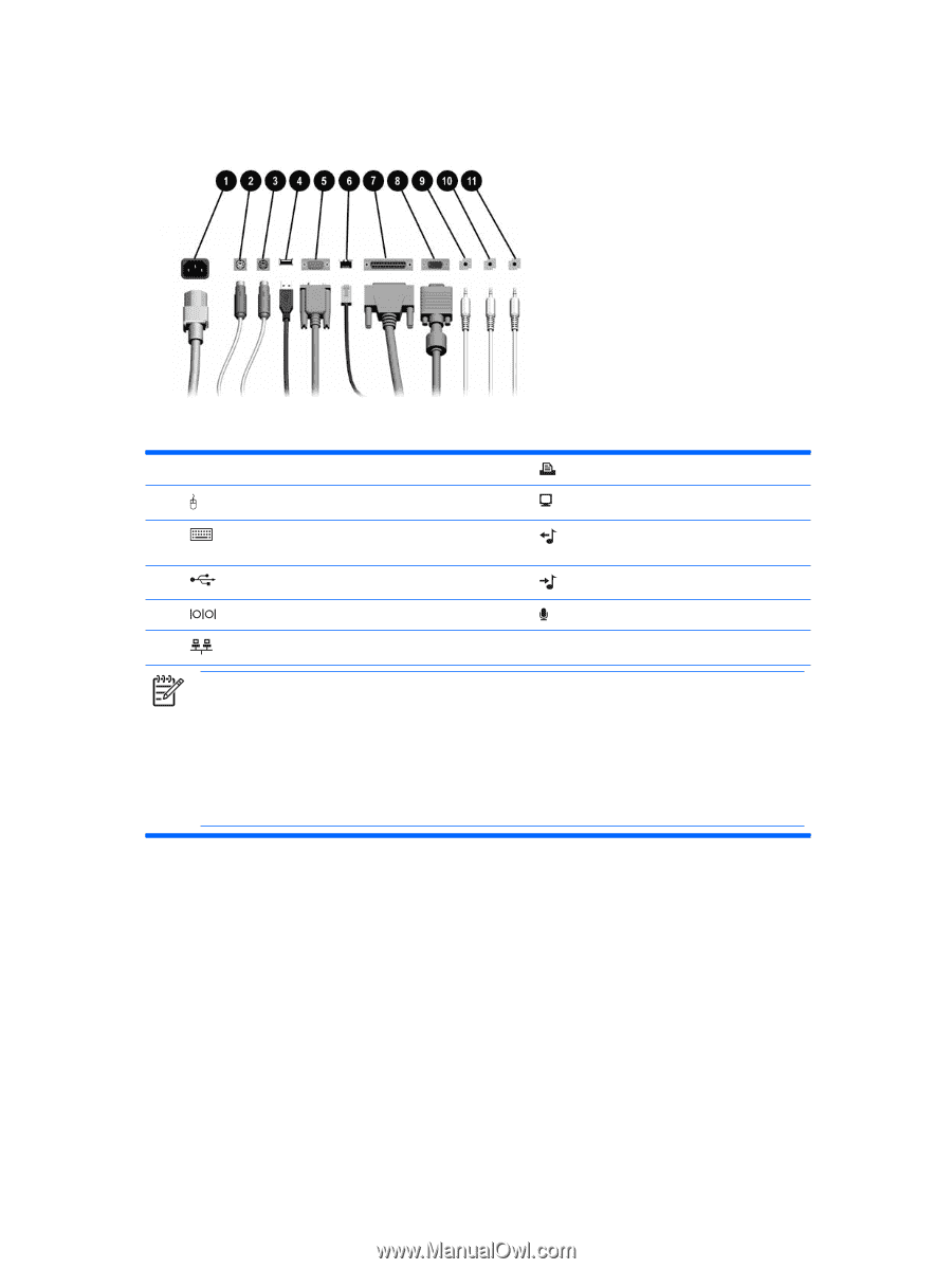
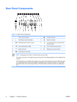
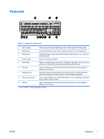
Rear Panel Components Table 1-3 Rear Panel Components 1 Power Cord Connector 2 PS/2 Mouse Connector (green) 3 PS/2 Keyboard Connector (purple) 4 Universal Serial Bus (USB) 5 Serial Connector 6 RJ-45 Network Connector 7 Parallel Connector 8 Monitor Connector 9 Line-Out Connector for powered audio devices (green) 10 Line-In Audio Connector (blue) 11 Microphone Connector (pink) NOTE Arrangement and number of connectors may vary by model. The monitor connector on the system board is inactive when a PCI Express graphics card is installed in the computer. If a PCI graphics card is installed, the connectors on the card and the system board may be used at the same time. Some settings may need to be changed in Computer Setup to use both connectors. For information about Boot Order, refer to the Computer Setup (F10) Utility Guide on the Documentation and Diagnostics CD. 4 Chapter 1 Product Features ENWW
-
 1
1 -
2
-
3
-
4
-
 5
5 -
 6
6 -
 7
7 -
 8
8 -
 9
9 -
 10
10 -
 11
11 -
 12
12 -
 13
13 -
 14
14 -
 15
15 -
16
-
17
-
18
-
19
-
20
-
21
-
22
-
23
-
24
-
25
-
26
-
27
-
28
-
29
-
30
-
31
-
32
-
33
-
34
-
35
-
36
-
37
-
38
-
39
-
40
-
41
-
42
-
43
-
44
-
45
-
46
-
47
-
48
-
49
-
50
-
51
-
52
-
53
-
54
-
55
-
56
-
57
-
58
-
59
-
60
 |
 |