Compaq dc7700 Hardware Reference Guide - dc7700 CMT - Page 35
Installing Additional Drives, Electrostatic Discharge
 |
View all Compaq dc7700 manuals
Add to My Manuals
Save this manual to your list of manuals |
Page 35 highlights
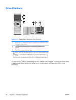
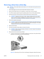
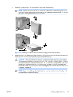
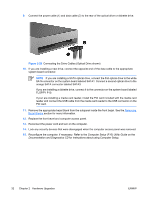
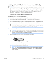
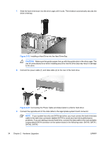
Installing Additional Drives The computer supports up to five drives that may be installed in various configurations. When installing additional drives, follow these guidelines: ● The primary Serial ATA (SATA) hard drive must be connected to the dark blue SATA connector on the system board labeled SATA0. ● Connect the first SATA optical drive to the white SATA connector on the system board labeled SATA1. ● Always populate the dark blue SATA0 and white SATA1 connectors before the light blue SATA2 and orange SATA3 connectors. ● Connect a second SATA optical drive to the orange SATA3 connector. ● Connect additional SATA hard drives to the next available (unpopulated) SATA connector on the system board in the following order: SATA0, SATA1, SATA3, SATA2. ● Connect a diskette drive to the connector labeled FLOPPY P10. ● The system does not support Parallel ATA (PATA) optical drives or PATA hard drives. ● You may install either a third-height or a half-height drive into a half-height bay. ● You must install guide screws to ensure the drive will line up correctly in the drive cage and lock in place. HP has provided extra guide screws installed on the chassis. The hard drive uses 6-32 standard screws, four of which are installed on the hard drive bracket under the access panel. All other drives use M3 metric screws, eight of which are installed on the diskette drive bracket under the access panel. The HP-supplied metric screws are black. The HP-supplied standard screws are silver. CAUTION To prevent loss of work and damage to the computer or drive: If you are inserting or removing a drive, shut down the operating system properly, turn off the computer, and unplug the power cord. Do not remove a drive while the computer is on or in standby mode. Before handling a drive, ensure that you are discharged of static electricity. While handling a drive, avoid touching the connector. For more information about preventing electrostatic damage, refer to Appendix D, Electrostatic Discharge. Handle a drive carefully; do not drop it. Do not use excessive force when inserting a drive. Avoid exposing a hard drive to liquids, temperature extremes, or products that have magnetic fields such as monitors or speakers. If a drive must be mailed, place the drive in a bubble-pack mailer or other protective packaging and label the package "Fragile: Handle With Care." ENWW Installing Additional Drives 29
-
 1
1 -
2
-
3
-
4
-
5
-
6
-
7
-
8
-
9
-
10
-
11
-
12
-
13
-
14
-
15
-
16
-
17
-
18
-
19
-
20
-
21
-
22
-
23
-
24
-
25
-
26
-
27
-
28
-
29
-
 30
30 -
 31
31 -
 32
32 -
 33
33 -
 34
34 -
 35
35 -
 36
36 -
 37
37 -
 38
38 -
 39
39 -
 40
40 -
41
-
42
-
43
-
44
-
45
-
46
-
47
-
48
-
49
-
50
-
51
-
52
-
53
-
54
-
55
-
56
-
57
-
58
-
59
-
60
 |
 |