Compaq dc7700 HP Compaq dc7700 Business Desktop PC Service Reference Guide, 1s
Compaq dc7700 - Convertible Minitower PC Manual
 |
View all Compaq dc7700 manuals
Add to My Manuals
Save this manual to your list of manuals |
Compaq dc7700 manual content summary:
- Compaq dc7700 | HP Compaq dc7700 Business Desktop PC Service Reference Guide, 1s - Page 1
service reference guide HP Compaq dc7700 Business PC 1st Edition This document provides information on the removal and replacement of all parts as well as information on troubleshooting, Desktop Management, setup utilities, PATA and SATA drives, safety, routine care, connector pin assignments, POST - Compaq dc7700 | HP Compaq dc7700 Business Desktop PC Service Reference Guide, 1s - Page 2
- Compaq dc7700 | HP Compaq dc7700 Business Desktop PC Service Reference Guide, 1s - Page 3
Service Reference Guide HP Compaq dc7700 Business PC dc7700 1st Edition Document Part Number: 433612-001 September 2006 - Compaq dc7700 | HP Compaq dc7700 Business Desktop PC Service Reference Guide, 1s - Page 4
Hewlett-Packard Development Company, L.P. The information contained herein is subject to change without notice. Microsoft, MS-DOS, Windows, Windows NT, and Windows XP loss of information. Service Reference Guide HP Compaq dc7700 Business PC First Edition (September 2006) Document Part Number: 433612- - Compaq dc7700 | HP Compaq dc7700 Business Desktop PC Service Reference Guide, 1s - Page 5
or Upgrading Device Drivers 1-1 1.2 Transferring Files and Settings 1-2 1.3 Creating a Disc Recovery Set 1-2 2 Setup Utilities and Diagnostics Features 2.1 Power-On Self-Test (POST 2-1 2.2 Computer Setup Utilities 2-2 2.2.1 Using Computer Setup (F10) Utilities 2-3 2.2.2 Computer Setup Menu - Compaq dc7700 | HP Compaq dc7700 Business Desktop PC Service Reference Guide, 1s - Page 6
4-2 4.3 PATA Device Information 4-3 4.4 ATA SMART Drives 4-3 4.5 Hard Drive Capacities 4-3 5 Identifying the Chassis, Routine Care, and Disassembly Preparation 5.1 Chassis Designations 5-1 5.1.1 Convertible Minitower (CMT 5-1 5.1.2 Small Form Factor (SFF 5-2 5.1.3 Ultra-Slim Desktop (USDT - Compaq dc7700 | HP Compaq dc7700 Business Desktop PC Service Reference Guide, 1s - Page 7
Contents 5.5 Service Considerations 5-7 5.5.1 Power Supply Fan 5-7 5.5.2 Tools and Software Requirements 5-7 5.5.3 Screws 5-8 5.5.4 Cables and Connectors 5-8 5.5.5 Hard Drives 5-8 5.5.6 Lithium Coin Cell Battery 5-9 6 Removal and Replacement Procedures - Convertible Minitower (CMT) Chassis - Compaq dc7700 | HP Compaq dc7700 Business Desktop PC Service Reference Guide, 1s - Page 8
and Replacement Procedures- Small Form Factor (SFF) Chassis 7.1 Preparation for Disassembly 7-1 7.2 Unlocking the Smart Cover Lock 7-2 7.3 Hood Sensor 7-4 7.4 External Security Devices 7-5 7.4.1 Security Clip 7-5 7.4.2 Cable Lock 7-5 7.4.3 Padlock 7-6 7.5 Computer Cover 7-7 7.6 Front Drive - Compaq dc7700 | HP Compaq dc7700 Business Desktop PC Service Reference Guide, 1s - Page 9
18 8.15Front I/O Device 8-20 8.16Heatsink Assembly 8-21 8.17Processor 8-22 8.18Power Supply 8-24 8.19System Power Cord Set Requirements C POST Error Messages D Troubleshooting Without Diagnostics E System Board and Riser Board Reference Designators F Memory Index Service Reference Guide, dc7700 - Compaq dc7700 | HP Compaq dc7700 Business Desktop PC Service Reference Guide, 1s - Page 10
Contents viii 433612-001 Service Reference Guide, dc7700 - Compaq dc7700 | HP Compaq dc7700 Business Desktop PC Service Reference Guide, 1s - Page 11
on how to purchase a support software CD subscription: http://h18000.www1.hp.com/support/files/desktops/us/purchase.html. ✎ If the computer has a writable optical drive, install the appropriate application to be able to write to the drive. Service Reference Guide, dc7700 433612-001 1-1 - Compaq dc7700 | HP Compaq dc7700 Business Desktop PC Service Reference Guide, 1s - Page 12
and Recovery Manager Manual. If Create factory software recovery CDs or DVDs to recover the system is unavailable on the system, the HP Restore Plus CD set can be obtained through product support on http://welcome/country/us/en/contact_us.html. 1-2 433612-001 Service Reference Guide, dc7700 - Compaq dc7700 | HP Compaq dc7700 Business Desktop PC Service Reference Guide, 1s - Page 13
provide information needed about the computer system when contacting Customer Support. These tools can also be computer system is functioning properly: ■ Keyboard ■ Memory modules ■ All mass storage devices ■ Processors ■ Controllers ✎ If the Power-On Service Reference Guide, dc7700 433612-001 2-1 - Compaq dc7700 | HP Compaq dc7700 Business Desktop PC Service Reference Guide, 1s - Page 14
settings for processor, graphics, memory, audio, storage, communications, and input devices. ■ Modify the boot order of bootable devices such as hard drives, diskette drives, optical drives, or USB flash media devices. ■ Enable Quick Boot, which is faster than Full Boot but does not run all - Compaq dc7700 | HP Compaq dc7700 Business Desktop PC Service Reference Guide, 1s - Page 15
system defaults. Ä CAUTION: Do NOT turn the computer power OFF while the BIOS is saving the F10 Computer Setup changes because the CMOS could become corrupted. It is safe to turn off all power to the computer only after exiting the F10 Setup screen. Service Reference Guide, dc7700 433612-001 2-3 - Compaq dc7700 | HP Compaq dc7700 Business Desktop PC Service Reference Guide, 1s - Page 16
without applying or saving any changes. Save Changes and Saves changes to system configuration or default settings and exits Exit Computer Setup. ✎ Support for specific Computer Setup options may vary depending on the hardware configuration. 2-4 433612-001 Service Reference Guide, dc7700 - Compaq dc7700 | HP Compaq dc7700 Business Desktop PC Service Reference Guide, 1s - Page 17
emulation options available CD-ROM drive No emulation options available ATAPI LS-120 None (treated as Other). Diskette (treated as diskette drive). ✎ Support for specific Computer Setup options may vary depending on the hardware configuration. Service Reference Guide, dc7700 433612-001 2-5 - Compaq dc7700 | HP Compaq dc7700 Business Desktop PC Service Reference Guide, 1s - Page 18
saving changes to Removable Media Write, the computer will restart. Turn the computer off, then on, manually. BIOS DMA Data Transfers Allows you to control how BIOS device I/O requests are serviced. When "Enable" is selected, the BIOS will service ATA device read and write requests with DMA data - Compaq dc7700 | HP Compaq dc7700 Business Desktop PC Service Reference Guide, 1s - Page 19
to enable DOS and boot accesses to SATA devices using the AHCI interface. Select this mode if the target operating system supports accessing the SATA devices via AHCI (e.g. Windows Vista) and AHCI accesses are desired. ✎ Windows 2000 and Windows XP require a third-party device driver to access - Compaq dc7700 | HP Compaq dc7700 Business Desktop PC Service Reference Guide, 1s - Page 20
is required for warm boot (CTRL+ALT+DEL) (appears if a power-on password is set) • Enable/Disable Setup Browse Mode (appears if a setup password is set) (allows viewing, but not changing, the F10 Setup Options without entering setup password) ✎ Support for specific Computer Setup options may vary - Compaq dc7700 | HP Compaq dc7700 Business Desktop PC Service Reference Guide, 1s - Page 21
is supported on some models only. Device Security Enables/disables serial ports, parallel port, all USB ports, system audio, network controllers (some models), SMBus controller (some models), and embedded security device (some models). Network Service Boot Enables/disables the computer's ability - Compaq dc7700 | HP Compaq dc7700 Business Desktop PC Service Reference Guide, 1s - Page 22
bar graph controls the minimum permitted fan speed. ✎ This setting only changes the minimum fan speed. The fans are still automatically controlled. ✎ Support for specific Computer Setup options may vary depending on the hardware configuration. 2-10 433612-001 Service Reference Guide, dc7700 - Compaq dc7700 | HP Compaq dc7700 Business Desktop PC Service Reference Guide, 1s - Page 23
slowly that they are not ready to boot by the time POST is finished. The POST delay also gives you more time to press F10 to enter Computer (F10) Setup. ✎ Support for specific Computer Setup options may vary depending on the hardware configuration. Service Reference Guide, dc7700 433612-001 2-11 - Compaq dc7700 | HP Compaq dc7700 Business Desktop PC Service Reference Guide, 1s - Page 24
"boot" or primary VGA controller. ✎ In order to see this entry, you must enable integrated video (Advanced > Device Options) and Save Changes and Exit. ✎ Support for specific Computer Setup options may vary depending on the hardware configuration. 2-12 433612-001 Service Reference Guide, dc7700 - Compaq dc7700 | HP Compaq dc7700 Business Desktop PC Service Reference Guide, 1s - Page 25
• Internal speaker (some models) (does not affect external speakers) • Monitor Tracking (enable/disable). Allows BIOS to save monitor asset information. ✎ Support for specific Computer Setup options may vary depending on the hardware configuration. Service Reference Guide, dc7700 433612-001 2-13 - Compaq dc7700 | HP Compaq dc7700 Business Desktop PC Service Reference Guide, 1s - Page 26
F10 option will allow users to disable the downloading of this embedded NIC option ROM thus giving more DCH space for additional PCI cards which may need option ROM space. The default will be to have the NIC option ROM enabled. ✎ Support for specific Computer Setup options may vary depending on the - Compaq dc7700 | HP Compaq dc7700 Business Desktop PC Service Reference Guide, 1s - Page 27
you a listing of general information about the computer. Architecture-Provides system BIOS and PCI device information. Asset Control-Shows asset tag, system serial number, and processor information. Communication-Shows information about the computer parallel (LPT) and serial (COM) port settings - Compaq dc7700 | HP Compaq dc7700 Business Desktop PC Service Reference Guide, 1s - Page 28
Interactive mode, but these require user intervention. ■ Custom Test-Provides the most flexibility in controlling the testing of a system. The Custom Test mode allows you to specifically select which devices, tests, and test parameters are run. There are two test modes to choose from: ■ Interactive - Compaq dc7700 | HP Compaq dc7700 Business Desktop PC Service Reference Guide, 1s - Page 29
of tests executed. This enables you to re-run the problem. To find an error code description quickly, enter the code in the box at the top of the tab and click the Find Error Codes button. The Test Components tab displays low level information on tests that are run. Service Reference Guide, dc7700 - Compaq dc7700 | HP Compaq dc7700 Business Desktop PC Service Reference Guide, 1s - Page 30
Select the specific product. 5. Select the OS. 6. Click the Diagnostics link. 7. Select HP Insight Diagnostics Offline Edition. 8. Select the proper language and click Download. ✎ The download includes instructions on how to create the bootable CD. 2-18 433612-001 Service Reference Guide, dc7700 - Compaq dc7700 | HP Compaq dc7700 Business Desktop PC Service Reference Guide, 1s - Page 31
information to help you select the best deployment method. The Restore Plus! CD, ROM-based setup, and ACPI hardware provide further assistance with recovery of system software, configuration management and troubleshooting, and power management. Service Reference Guide, dc7700 433612-001 3-1 - Compaq dc7700 | HP Compaq dc7700 Business Desktop PC Service Reference Guide, 1s - Page 32
Desktop Management 3.1.1 HP OpenView Agent The Radia Management Agent (RMA) used by both HP OpenView Client Configuration Manager and HP OpenView PC Configuration Management Solutions (Radia) is pre-loaded on the computer. When installed, it enables communication with the HP OpenView management - Compaq dc7700 | HP Compaq dc7700 Business Desktop PC Service Reference Guide, 1s - Page 33
. Follow the instructions on the screen to continue the process. The default boot order is a BIOS configuration setting that can be changed to always attempt to PXE boot. 3.3 Software Updating and Management HP provides several tools for managing and updating software on desktops, workstations, and - Compaq dc7700 | HP Compaq dc7700 Business Desktop PC Service Reference Guide, 1s - Page 34
drivers and BIOS updates without visiting each PC ■ Remotely configure BIOS and security settings ■ Automate processes to quickly resolve hardware problems Tight integration with HP Instant Support tools reduces hardware troubleshooting time. ■ Diagnostics-remotely run & view reports on HP desktop - Compaq dc7700 | HP Compaq dc7700 Business Desktop PC Service Reference Guide, 1s - Page 35
for ProtectTools ■ BIOS Configuration for ProtectTools ■ Credential Manager for ProtectTools The modules available for your computer may vary depending on your model. For example, Embedded Security for ProtectTools requires that the Trusted Platform Module (TPM) embedded security chip (some models - Compaq dc7700 | HP Compaq dc7700 Business Desktop PC Service Reference Guide, 1s - Page 36
software related problems, and ensure the software supporting their business operations is reliable and secure. For more information on HP OpenView PC Configuration Management Solution, visit http://h20229.www2.hp.com/solutions/ascm/index.html. 3-6 433612-001 Service Reference Guide, dc7700 - Compaq dc7700 | HP Compaq dc7700 Business Desktop PC Service Reference Guide, 1s - Page 37
. For HP-specific information on Intel vPro technology, see the white papers at http://www.hp.com/support. Select your country and language, select See support and troubleshooting information, enter the model number of the computer, and press Enter. In the Resources category, click Manuals (guides - Compaq dc7700 | HP Compaq dc7700 Business Desktop PC Service Reference Guide, 1s - Page 38
to reset AMT configuration to factory defaults ❏ VLAN-allows administrator to enable LAN virtualization support ❏ SOL/IDE-R-allows administrator to enable remote boot and control sessions ■ Change MEBx Password (HP highly recommends that this password be changed. The default password is admin - Compaq dc7700 | HP Compaq dc7700 Business Desktop PC Service Reference Guide, 1s - Page 39
. Enabling the system administrator to perform this task remotely on multiple computers results in a consistent deployment of, and greater control over, HP PC BIOS images over the network. It also results in greater productivity and lower total cost of ownership. ✎ The computer must be powered on - Compaq dc7700 | HP Compaq dc7700 Business Desktop PC Service Reference Guide, 1s - Page 40
to locally update or restore the system BIOS on individual PCs through a Windows operating system. For more information on HPQFlash, visit http://www.hp.com/support/files and enter the product name/number of the computer when prompted. 3.4.3 Boot Block Emergency Recovery Mode Boot Block Emergency - Compaq dc7700 | HP Compaq dc7700 Business Desktop PC Service Reference Guide, 1s - Page 41
for faster, more consistent configuration of multiple computers. ✎ Both procedures require a diskette drive or a supported USB flash media device, such as an HP Drive Key. Copying to Single Computer Ä CAUTION: A setup configuration is model-specific. File system corruption may result if source - Compaq dc7700 | HP Compaq dc7700 Business Desktop PC Service Reference Guide, 1s - Page 42
USB flash media device. If Windows XP is not available to use to create a bootable diskette, use the method for copying to a single computer instead (see "Copying to Single Computer"). 1. Create a bootable diskette or USB flash media device. See "Supported USB Flash Media Device" or "Unsupported USB - Compaq dc7700 | HP Compaq dc7700 Business Desktop PC Service Reference Guide, 1s - Page 43
Desktop Management Creating a Bootable Device Supported USB Flash Media Device Supported devices have a preinstalled image to simplify the process of making them bootable. All HP or Compaq and most other USB flash media devices have this preinstalled image. If the USB flash media device being used - Compaq dc7700 | HP Compaq dc7700 Business Desktop PC Service Reference Guide, 1s - Page 44
the hard drive, the computer can be booted from a USB flash media device. Otherwise, a bootable diskette must be used. 1. If there are any PCI cards in the system that have SCSI, ATA RAID, or SATA drives attached, turn off the computer and unplug the power cord. Ä CAUTION: The power cord MUST be - Compaq dc7700 | HP Compaq dc7700 Business Desktop PC Service Reference Guide, 1s - Page 45
Advanced > PCI Devices and re-enable the PATA and SATA controllers that were disabled in step 6. Put the SATA controller on its original IRQ. 16. Save the changes and exit. The computer will boot to the USB flash media device as drive C. ✎ The default boot order varies from computer to computer, and - Compaq dc7700 | HP Compaq dc7700 Business Desktop PC Service Reference Guide, 1s - Page 46
latest support software easier. You can download the software from http://www.hp.com/support. The Web site contains the latest device drivers, utilities, and flashable ROM images needed to run the latest Microsoft Windows operating system on the HP computer. 3.4.7 Industry Standards HP management - Compaq dc7700 | HP Compaq dc7700 Business Desktop PC Service Reference Guide, 1s - Page 47
• Enable/disable the Embedded Security device. • Reset the device to Factory Settings. ✎ For more information about Computer Setup, see the Computer Setup (F10) Utility Guide. Support for security features may vary depending on your specific computer configuration. Service Reference Guide, dc7700 - Compaq dc7700 | HP Compaq dc7700 Business Desktop PC Service Reference Guide, 1s - Page 48
(Continued) Option Description Device Security Enables/disables serial ports, parallel port, front USB ports, system audio, network controllers (some models), and SCSI controllers (some models). Network Service Boot Enables/disables the computer's ability to boot from an operating system - Compaq dc7700 | HP Compaq dc7700 Business Desktop PC Service Reference Guide, 1s - Page 49
enable the system administrator to log in to all network systems to perform maintenance without having to know the power-on password, even if one has been established. 3.5.2 Establishing a Setup Password Using Computer Setup If the system is equipped with an embedded security device, refer to the HP - Compaq dc7700 | HP Compaq dc7700 Business Desktop PC Service Reference Guide, 1s - Page 50
Boot. When Password Prompt on Warm Boot is enabled, the password must also be entered each time the computer is rebooted. 1. Turn on or restart the computer. If you are in Windows turn off the computer, then turn it on again before you can continue. 3-20 433612-001 Service Reference Guide, dc7700 - Compaq dc7700 | HP Compaq dc7700 Business Desktop PC Service Reference Guide, 1s - Page 51
Desktop Management Changing a Power-On or Setup Password If the system is equipped with an embedded security device, refer to the HP ProtectTools Security Manager Guide at www.hp.com. 1. Turn on or restart the computer. If you are in Windows, click Start > Shut Down > Restart. 2. To change the Power - Compaq dc7700 | HP Compaq dc7700 Business Desktop PC Service Reference Guide, 1s - Page 52
computer. Refer to the Troubleshooting Guide on the Documentation and Diagnostics CD for instructions on clearing passwords. If the system is equiped with an embedded security device, refer to the HP ProtectTools Security Manager Guide at www.hp . 3-22 433612-001 Service Reference Guide, dc7700 - Compaq dc7700 | HP Compaq dc7700 Business Desktop PC Service Reference Guide, 1s - Page 53
been designed to protect. Access to Computer Setup and DriveLock can be restricted through the Setup password. By specifying a Setup password and not giving it to end users, system administrators are able to restrict users from enabling DriveLock. Service Reference Guide, dc7700 433612-001 3-23 - Compaq dc7700 | HP Compaq dc7700 Business Desktop PC Service Reference Guide, 1s - Page 54
is a software-controllable cover lock featured on some HP computers. This lock prevents unauthorized access to the internal components. Computers ship with the Computer Setup utility. ✎ The Smart Cover Lock is available as an option on some systems. 3-24 433612-001 Service Reference Guide, dc7700 - Compaq dc7700 | HP Compaq dc7700 Business Desktop PC Service Reference Guide, 1s - Page 55
enable the Smart Cover Lock and cannot enter your password to disable the lock, you will need a Smart Cover FailSafe Key to open the computer cover. You will need the key in any of the following circumstances: ■ Power outage ■ Startup failure ■ PC component failure (such as processor or power supply - Compaq dc7700 | HP Compaq dc7700 Business Desktop PC Service Reference Guide, 1s - Page 56
hard drive. Your service provider can use this information to help diagnose conditions that caused you to run the DPS software. Refer to the Troubleshooting Guide for instructions on using DPS. 3.6.2 Surge-Tolerant Power Supply An integrated surge-tolerant power supply provides greater reliability - Compaq dc7700 | HP Compaq dc7700 Business Desktop PC Service Reference Guide, 1s - Page 57
Guidelines and Features ✎ Serial ATA = SATA Parallel ATA = PATA HP only supports the use of SATA hard drives on these models of computer. The USDT model is the only product that supports a PATA optical drive. No PATA drives are supported on any other model. 4.1 SATA Hard Drives Serial ATA Hard - Compaq dc7700 | HP Compaq dc7700 Business Desktop PC Service Reference Guide, 1s - Page 58
V power P3 V3.3 3.3 V power P4 Ground P5 Ground P6 Ground P7 V5 5 V power P8 V5 5 V power Pin Usage Notes P9 V5 5 V power P10 Ground P11 Ground P12 Ground P13 V 12 12 V power P14 V12 12 V power P15 V12 12 V power 4-2 433612-001 Service Reference Guide, dc7700 - Compaq dc7700 | HP Compaq dc7700 Business Desktop PC Service Reference Guide, 1s - Page 59
10 while calculations by Microsoft are bytes to the base 2. Drive/Partition Capacity Limits File System FAT 32 NTFS Controller Type ATA ATA Operating System Windows 2000/ XP Windows NT/2000/XP Maximum Size Partition 32 GB 2 TB Drive 2 TB 2 TB Service Reference Guide, dc7700 433612-001 4-3 - Compaq dc7700 | HP Compaq dc7700 Business Desktop PC Service Reference Guide, 1s - Page 60
Serial and Parallel ATA Drive Guidelines and Features 4-4 433612-001 Service Reference Guide, dc7700 - Compaq dc7700 | HP Compaq dc7700 Business Desktop PC Service Reference Guide, 1s - Page 61
an AC power source, voltage is always applied to the system board. You must disconnect the power cord from the power source before opening the computer to prevent system board or component damage. 5.1 Chassis Designations 5.1.1 Convertible Minitower (CMT) Service Reference Guide, dc7700 433612-001 - Compaq dc7700 | HP Compaq dc7700 Business Desktop PC Service Reference Guide, 1s - Page 62
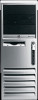
Identifying the Chassis, Routine Care, and Disassembly Preparation 5.1.2 Small Form Factor (SFF) 5.1.3 Ultra-Slim Desktop (USDT) 5-2 433612-001 Service Reference Guide, dc7700 - Compaq dc7700 | HP Compaq dc7700 Business Desktop PC Service Reference Guide, 1s - Page 63
protection, but in many cases, the discharge contains enough power to alter device parameters or melt silicon junctions. 5.2.1 Generating Static The following electrostatic-sensitive parts from assemblies in protective packaging or conductive foam. Service Reference Guide, dc7700 433612-001 5-3 - Compaq dc7700 | HP Compaq dc7700 Business Desktop PC Service Reference Guide, 1s - Page 64
/Toe straps/Boot straps can be used at standing workstations and are compatible with most types of shoes or boots. On conductive at static-free work areas. ■ Turn off power and input signals before inserting and removing connectors or service kits 5-4 433612-001 Service Reference Guide, dc7700 - Compaq dc7700 | HP Compaq dc7700 Business Desktop PC Service Reference Guide, 1s - Page 65
apply. ■ Keep liquids away from the computer and keyboard. ■ Never cover the ventilation slots on the monitor with any type of material. ■ Install or enable power management functions of the operating system or other software, including sleep states. Service Reference Guide, dc7700 433612-001 5-5 - Compaq dc7700 | HP Compaq dc7700 Business Desktop PC Service Reference Guide, 1s - Page 66
vents on the computer. Lint and other clean the tops of the supply outlets. Ä CAUTION: Never remove a wide leveled key (like the space bar) from the keyboard. If these keys are improperly removed or installed, the keyboard may not function properly. 5-6 433612-001 Service Reference Guide, dc7700 - Compaq dc7700 | HP Compaq dc7700 Business Desktop PC Service Reference Guide, 1s - Page 67
from the power source before opening the computer to prevent system board or component damage. 5.5.2 Tools and Software Requirements To service the computer, you need the following: ■ Torx T-15 screwdriver (HP screwdriver with bits, PN 161946-001) ■ Torx T-15 screwdriver with small diameter shank - Compaq dc7700 | HP Compaq dc7700 Business Desktop PC Service Reference Guide, 1s - Page 68
the CPU. ■ Avoid dropping drives from any height onto any surface. ■ If you are inserting or removing a hard drive, turn off the computer. Do not remove a hard drive while the computer is on that have magnetic fields such as monitors or speakers. 5-8 433612-001 Service Reference Guide, dc7700 - Compaq dc7700 | HP Compaq dc7700 Business Desktop PC Service Reference Guide, 1s - Page 69
Preparation 5.5.6 Lithium Coin Cell Battery The battery that comes with the computer provides power to the real-time clock and has a minimum lifetime of about three collection system or return them to HP, their authorized partners, or their agents. Service Reference Guide, dc7700 433612-001 5-9 - Compaq dc7700 | HP Compaq dc7700 Business Desktop PC Service Reference Guide, 1s - Page 70
Identifying the Chassis, Routine Care, and Disassembly Preparation 5-10 433612-001 Service Reference Guide, dc7700 - Compaq dc7700 | HP Compaq dc7700 Business Desktop PC Service Reference Guide, 1s - Page 71
6 Removal and Replacement Procedures Convertible Minitower (CMT) Chassis Adherence to the procedures and precautions described in this chapter is essential for proper service. After completing all necessary removal and replacement procedures, run the diagnostics utility to verify that all components - Compaq dc7700 | HP Compaq dc7700 Business Desktop PC Service Reference Guide, 1s - Page 72
Convertible Minitower (CMT) Chassis 6.2 Unlocking the Smart Cover Lock If you have locked the Smart Cover Lock use Computer Setup to unlock the lock. Refer to the Desktop Management Guide on the Documentation and Diagnostics CD ■ Power outage ■ Startup failure ■ Processor or power supply failure ■ - Compaq dc7700 | HP Compaq dc7700 Business Desktop PC Service Reference Guide, 1s - Page 73
Removal and Replacement Procedures - Convertible Minitower (CMT) Chassis 6.3 Hood Sensor 1. Prepare the computer for disassembly (Section 6.1). 2. the computer 1 and lower it down through the slot 2. To install the hood sensor, reverse the removal procedure. Service Reference Guide, dc7700 - Compaq dc7700 | HP Compaq dc7700 Business Desktop PC Service Reference Guide, 1s - Page 74
Removal and Replacement Procedures - Convertible Minitower (CMT) Chassis 6.4 External Security Devices 6.4.1 Cable Lock The cable lock may be used to secure the computer access panel to the chassis and, at the same time, secure the computer to a fixed object. 6.4.2 Padlock A padlock may be used by - Compaq dc7700 | HP Compaq dc7700 Business Desktop PC Service Reference Guide, 1s - Page 75
Removal and Replacement Procedures - Convertible Minitower (CMT) Chassis 6.5 Computer Access Panel 1. Prepare the computer for disassembly (Section 6.1). Ä CAUTION: Before removing the computer access panel, ensure that the computer is turned off and that the power cord is disconnected from the - Compaq dc7700 | HP Compaq dc7700 Business Desktop PC Service Reference Guide, 1s - Page 76
Removal and Replacement Procedures - Convertible Minitower (CMT) Chassis 6.6 Front Bezel 1. Prepare the computer for disassembly (Section 6.1). 2. Remove the computer access panel (Section 6.5). 3. Push up on the two release tabs 1, then rotate the front bezel away from the chassis to release it - Compaq dc7700 | HP Compaq dc7700 Business Desktop PC Service Reference Guide, 1s - Page 77
Removal and Replacement Procedures - Convertible Minitower (CMT) Chassis 6.7 Front Drive Bezels 1. Prepare the computer for disassembly (Section 6.1). 2. Remove the access panel (Section 6.5). 3. the bottom of the subpanel when properly oriented. Service Reference Guide, dc7700 433612-001 6-7 - Compaq dc7700 | HP Compaq dc7700 Business Desktop PC Service Reference Guide, 1s - Page 78
Removal and Replacement Procedures - Convertible Minitower (CMT) Chassis 6.7.2 Diskette Drive Bezel or Bezel Blank Press up on the two small retaining clips 1 on the bottom of the bezel insert, press down on the two small retaining clips 2 on the top of the insert, and push the cover out of the - Compaq dc7700 | HP Compaq dc7700 Business Desktop PC Service Reference Guide, 1s - Page 79
and Replacement Procedures - Convertible Minitower (CMT) Chassis 6.8 Cable Management Always follow good cable management practices when working inside the computer. ■ Keep cables away from major heat sources like the heatsink. ■ Do not jam cables on top of expansion cards or memory modules. Printed - Compaq dc7700 | HP Compaq dc7700 Business Desktop PC Service Reference Guide, 1s - Page 80
power CPU power 1st ODD or 2nd HDD if no ODD present, SATA1 1st Hard drive, SATA0 PATA/Zip/Media card reader Diskette drive SATA hard/optical drive - Bay 1 only 2nd or 4th HDD if no Odd presenT, SATA2 2nd ODD or 3rd HDD if no ODD present, SATA3 6-10 433612-001 Service Reference Guide, dc7700 - Compaq dc7700 | HP Compaq dc7700 Business Desktop PC Service Reference Guide, 1s - Page 81
Removal and Replacement Procedures - Convertible Minitower (CMT) Chassis 6.9 Memory CAUTION: The memory module sockets have gold metal contacts. When upgrading the memory, it is important to use memory modules with gold metal contacts to prevent corrosion and/or oxidation resulting from having - Compaq dc7700 | HP Compaq dc7700 Business Desktop PC Service Reference Guide, 1s - Page 82
and Replacement Procedures - Convertible Minitower (CMT) Chassis ✎ The computer automatically recognizes the additional memory when the computer is turned on. To reassemble the computer, reverse the removal procedure. ✎ If you normally lock the Smart Cover Lock, use Computer Setup to relock the - Compaq dc7700 | HP Compaq dc7700 Business Desktop PC Service Reference Guide, 1s - Page 83
Removal and Replacement Procedures - Convertible Minitower (CMT) Chassis 5. If you are installing an expansion card in a vacant socket, remove the installed expansion card, disconnect any cables that may be attached to the expansion card. Service Reference Guide, dc7700 433612-001 6-13 - Compaq dc7700 | HP Compaq dc7700 Business Desktop PC Service Reference Guide, 1s - Page 84
Removal and Replacement Procedures - Convertible Minitower (CMT) Chassis 7. If you are removing a PCI Express card from a x16 PCI Express socket with a retention mechanism, pull the retention proper cooling of internal components during operation. 6-14 433612-001 Service Reference Guide, dc7700 - Compaq dc7700 | HP Compaq dc7700 Business Desktop PC Service Reference Guide, 1s - Page 85
Lock, use Computer Setup to relock the lock and enable the Smart Cover Sensor. 15. Reconfigure the computer, if necessary. Refer to the Computer Setup (F10) Utility Guide on the Documentation and Diagnostics CD for instructions about using Computer Setup. Service Reference Guide, dc7700 433612-001 - Compaq dc7700 | HP Compaq dc7700 Business Desktop PC Service Reference Guide, 1s - Page 86
Removal and Replacement Procedures - Convertible Minitower (CMT) Chassis 6.11 PCI Retainer Latch 1. Prepare the computer for disassembly (Section 6.1). 2. Remove the computer access panel (Section 6.5). by pulling the latches off the pivoting bar 2. 6-16 433612-001 Service Reference Guide, dc7700 - Compaq dc7700 | HP Compaq dc7700 Business Desktop PC Service Reference Guide, 1s - Page 87
Removal and Replacement Procedures - Convertible Minitower (CMT) Chassis 6. Slide the pivoting bar to the right 1, then lift the left end 2 to remove it in place on the rotating bar. ✎ The green latches are marked "R" and "L" for your convenience. Service Reference Guide, dc7700 433612-001 6-17 - Compaq dc7700 | HP Compaq dc7700 Business Desktop PC Service Reference Guide, 1s - Page 88
Removal and Replacement Procedures - Convertible Minitower (CMT) Chassis 6.12 Expansion Card Guide 1. Prepare the computer for disassembly (Section 6.1). 2. Remove the computer access panel (Section 6.5). 3. Remove any expansion cards that might be in the way (Section 6.10). 4. Compress the - Compaq dc7700 | HP Compaq dc7700 Business Desktop PC Service Reference Guide, 1s - Page 89
- Convertible Minitower (CMT) Chassis 6.13 Drives The computer supports up to six drives that may be installed in various configurations. This Section describes the procedure for replacing or upgrading the storage drives. A Torx T-15 screwdriver is needed to remove and install the guide screws - Compaq dc7700 | HP Compaq dc7700 Business Desktop PC Service Reference Guide, 1s - Page 90
Removal and Replacement Procedures - Convertible Minitower (CMT) Chassis 6.13.2 Hard Drive Ä CAUTION: To prevent loss of work and damage to the computer or drive: ■ If you are inserting or removing a hard drive, shut down the operating system properly, then turn off the computer. Do not remove a - Compaq dc7700 | HP Compaq dc7700 Business Desktop PC Service Reference Guide, 1s - Page 91
Removal and Replacement Procedures - Convertible Minitower (CMT) Chassis 5. Pull up on the green hard drive drivelock mechanism 1 for that drive and slide the drive from the drive bay 2 . 6. Remove the four guide screws (two on each side) from the old drive and install them in the replacement drive - Compaq dc7700 | HP Compaq dc7700 Business Desktop PC Service Reference Guide, 1s - Page 92
cable. 5. If the computer is in the desktop mode, continue with step 7. If the computer is in the minitower mode, continue with step 8. 6. In the desktop mode, press down on the yellow drivelock mechanism 1 and slide the drive from the drive bay 2. 6-22 433612-001 Service Reference Guide, dc7700 - Compaq dc7700 | HP Compaq dc7700 Business Desktop PC Service Reference Guide, 1s - Page 93
Removal and Replacement Procedures - Convertible Minitower (CMT) Chassis 7. In the minitower mode, pull up on the green drivelock mechanism 1 for that specific drive and slide the drive from the drive bay 2. 8. Remove the four guide screws (two on each side) from the old drive and install them in - Compaq dc7700 | HP Compaq dc7700 Business Desktop PC Service Reference Guide, 1s - Page 94
optimum performance. 12. Replace the front bezel (Section 6.6). 13. Replace the computer access panel (Section 6.5) 14. If you normally lock the Smart Cover Lock, use Computer Setup to relock the lock and enable the Smart Cover Sensor (Section 6.2). 6-24 433612-001 Service Reference Guide, dc7700 - Compaq dc7700 | HP Compaq dc7700 Business Desktop PC Service Reference Guide, 1s - Page 95
and power cables to the drive. 8. Replace the front bezel (Section 6.6). 9. Replace the computer access panel (Section 6.5). 10. If you normally lock the Smart Cover Lock, use Computer Setup to relock the lock and enable the Smart Cover Sensor (Section 6.2). Service Reference Guide, dc7700 433612 - Compaq dc7700 | HP Compaq dc7700 Business Desktop PC Service Reference Guide, 1s - Page 96
Removal and Replacement Procedures - Convertible Minitower (CMT) Chassis 6.14 Front I/O Device 1. Prepare the computer for disassembly (Section 6.1). 2. Remove the computer access panel (Section 6.5). 3. Remove the front bezel (Section 6.6). 4. Disconnect the two I/O device cables from the system - Compaq dc7700 | HP Compaq dc7700 Business Desktop PC Service Reference Guide, 1s - Page 97
Removal and Replacement Procedures - Convertible Minitower (CMT) Chassis 6.15 Power Switch Assembly 1. Prepare the computer for disassembly (Section 6.1). 2. Remove the computer access panel (Section 6.5). 3. Remove the front bezel (Section 6.6). 4. Disconnect the power switch/LED cable from the - Compaq dc7700 | HP Compaq dc7700 Business Desktop PC Service Reference Guide, 1s - Page 98
Removal and Replacement Procedures - Convertible Minitower (CMT) Chassis 6.16 System Board 1. Prepare the computer for disassembly (Section 6.1). 2. Remove the computer access panel (Section 6.5). 3. Remove all PCI expansion boards (Section 6.10). 4. Remove the x16 PCI Express graphics card (Section - Compaq dc7700 | HP Compaq dc7700 Business Desktop PC Service Reference Guide, 1s - Page 99
and Replacement Procedures - Convertible Minitower (CMT) Chassis 6.17 Battery The 3-volt lithium coin cell battery that comes with this computer provides power to the real- system board, complete the following instructions to replace the battery: Service Reference Guide, dc7700 433612-001 6-29 - Compaq dc7700 | HP Compaq dc7700 Business Desktop PC Service Reference Guide, 1s - Page 100
. 4. Replace the computer access panel. 5. Plug in the computer and turn on power to the computer. 6. Reset the date and time, your passwords, and any special system setups, using Computer Setup. Refer to the Computer Setup (F10) Utility Guide. 6-30 433612-001 Service Reference Guide, dc7700 - Compaq dc7700 | HP Compaq dc7700 Business Desktop PC Service Reference Guide, 1s - Page 101
- Convertible Minitower (CMT) Chassis computer access panel. 4. Plug in the computer and turn on power to the computer. 5. Reset the date and time, your passwords, and any special system setups, using Computer Setup. Refer to the Computer Setup (F10) Utility Guide. Service Reference Guide, dc7700 - Compaq dc7700 | HP Compaq dc7700 Business Desktop PC Service Reference Guide, 1s - Page 102
- Convertible Minitower (CMT) Chassis 6.17.3 Type 3 Battery Holder 1. Pull back on the clip 1 that holds the battery in place, then remove the battery 2. 2. Insert the new battery and position the clip back in place. 3. Replace the computer access panel. 4. Plug in the computer and turn on power to - Compaq dc7700 | HP Compaq dc7700 Business Desktop PC Service Reference Guide, 1s - Page 103
Convertible Minitower (CMT) Chassis 6.18 Heatsink 1. Prepare the computer for disassembly (Section 6.1). 2. Remove the computer access panel (Section 6.5). 3. Disconnect the heatsink control has been applied to the top of the processor. Ä CAUTION Service Reference Guide, dc7700 433612-001 6-33 - Compaq dc7700 | HP Compaq dc7700 Business Desktop PC Service Reference Guide, 1s - Page 104
Convertible Minitower (CMT) Chassis 6.19 Processor 1. Prepare the computer for disassembly (Section 6.1). 2. Remove the computer access panel (Section 6.5). 3. Disconnect the heatsink control provided in the spares kit to the top of the processor. 4. Clean the bottom Service Reference Guide, dc7700 - Compaq dc7700 | HP Compaq dc7700 Business Desktop PC Service Reference Guide, 1s - Page 105
onto the system board, always update the system ROM to ensure that the latest version of the BIOS is being used on the computer. The latest system BIOS can be found on the Web at: http:\\h18000.www1.hp.com/support/files. 6.20 Speaker 1. Prepare the computer for disassembly (Section 6.1). 2. Remove - Compaq dc7700 | HP Compaq dc7700 Business Desktop PC Service Reference Guide, 1s - Page 106
Procedures - Convertible Minitower (CMT) Chassis 6.21 Chassis Fan 1. Prepare the computer for disassembly (Section 6.1). 2. Remove the computer access panel (Section 6.5). 3. Disconnect the fan control cable housing for proper air flow orientation. 6-36 433612-001 Service Reference Guide, dc7700 - Compaq dc7700 | HP Compaq dc7700 Business Desktop PC Service Reference Guide, 1s - Page 107
and Replacement Procedures - Convertible Minitower (CMT) Chassis 6.22 Power Supply Å WARNING: Voltage is always present on the system board when the computer is plugged into an active AC outlet. To avoid possible personal injury and damage to the equipment the power cord should be disconnected - Compaq dc7700 | HP Compaq dc7700 Business Desktop PC Service Reference Guide, 1s - Page 108
Convertible Minitower (CMT) Chassis 4. With the power supply stopped by the retaining clips 1, lift the power supply to raise it over the clips then slide the power supply forward 2 to remove it from the computer. To install the power supply, reverse the removal procedure. 6-38 433612-001 Service - Compaq dc7700 | HP Compaq dc7700 Business Desktop PC Service Reference Guide, 1s - Page 109
and Replacement Procedures - Convertible Minitower (CMT) Chassis 6.23 Changing from Desktop to Minitower 1. Prepare the computer for disassembly (Section 6.1). 2. Remove the computer access panel (Section 6.5). 3. Remove the front bezel (Section 6.6). 4. Disconnect all power and data cables from - Compaq dc7700 | HP Compaq dc7700 Business Desktop PC Service Reference Guide, 1s - Page 110
Convertible Minitower (CMT shorter depth than the upper two bays. The bottom bay supports a drive that is no more than 17 cm (6.7 result in damage to the drive. 8. Reconnect all power and data cables to the drives in the 5.25 minitower configuration. 6-40 433612-001 Service Reference Guide, dc7700 - Compaq dc7700 | HP Compaq dc7700 Business Desktop PC Service Reference Guide, 1s - Page 111
, then snap it back into the bezel. 12. Replace the front bezel and computer access panel. 13. Reconnect the external equipment. 14. If you normally lock the Smart Cover Lock, use Computer Setup to relock the lock and enable the Smart Cover Sensor. Service Reference Guide, dc7700 433612-001 6-41 - Compaq dc7700 | HP Compaq dc7700 Business Desktop PC Service Reference Guide, 1s - Page 112
Convertible Minitower (CMT) Chassis 6.24 Changing from Minitower to Desktop 1. Prepare the computer for disassembly (Section 6.1). 2. Remove the computer access panel (Section 6.5). 3. Remove the front bezel (Section 6.6). 4. Disconnect all power . 6-42 433612-001 Service Reference Guide, dc7700 - Compaq dc7700 | HP Compaq dc7700 Business Desktop PC Service Reference Guide, 1s - Page 113
Convertible Minitower (CMT shorter depth than the upper two bays. The bottom bay supports a drive that is no more than 17 cm (6.7 result in damage to the drive. 8. Reconnect all power and data cables to the drives in the 5.25 desktop configuration. Service Reference Guide, dc7700 433612-001 6-43 - Compaq dc7700 | HP Compaq dc7700 Business Desktop PC Service Reference Guide, 1s - Page 114
, then snap it back into the bezel. 12. Replace the front bezel and computer access panel. 13. Reconnect the external equipment. 14. If you normally lock the Smart Cover Lock, use Computer Setup to relock the lock and enable the Smart Cover Sensor. 6-44 433612-001 Service Reference Guide, dc7700 - Compaq dc7700 | HP Compaq dc7700 Business Desktop PC Service Reference Guide, 1s - Page 115
7 Removal and Replacement Procedures- Small Form Factor (SFF) Chassis Adherence to the procedures and precautions described in this chapter is essential for proper service. After completing all necessary removal and replacement procedures, run the Diagnostics utility to verify that all components - Compaq dc7700 | HP Compaq dc7700 Business Desktop PC Service Reference Guide, 1s - Page 116
Removal and Replacement Procedures- Small Form Factor (SFF) Chassis 7.2 Unlocking the Smart Cover Lock If you have locked the Smart Cover Lock use Computer Setup to unlock the lock. Refer to the Desktop Management Guide on the Documentation and Diagnostics CD for more information about the Smart - Compaq dc7700 | HP Compaq dc7700 Business Desktop PC Service Reference Guide, 1s - Page 117
Removal and Replacement Procedures- Small Form Factor (SFF) Chassis To reattach the Smart Cover Lock: 1. Install the Smart Cover Lock assembly on the inside of the rear panel with the metal arm 1 wrapped around the air vent grid on the back of the chassis. 2. Use the supplied tamper-resistant screw - Compaq dc7700 | HP Compaq dc7700 Business Desktop PC Service Reference Guide, 1s - Page 118
Removal and Replacement Procedures- Small Form Factor (SFF) Chassis 7.3 Hood Sensor 1. Prepare the computer for disassembly. 2. Remove the computer cover. 3. Remove the special security clip (Section 7.4.1) from the top corner of the power supply cage. 4. Raise the power supply to its full upright - Compaq dc7700 | HP Compaq dc7700 Business Desktop PC Service Reference Guide, 1s - Page 119
Removal and Replacement Procedures- Small Form Factor (SFF) Chassis 7.4 External Security Devices 7.4.1 Security Clip A special clip is required to secure the computer from intrusion. This clip must be installed before installing the computer cover. 7.4.2 Cable Lock The cable lock may be used to - Compaq dc7700 | HP Compaq dc7700 Business Desktop PC Service Reference Guide, 1s - Page 120
Replacement Procedures- Small Form Factor (SFF) Chassis 7.4.3 Padlock A padlock may be used by itself to secure the computer cover to the computer chassis. A padlock may also be used with a security cable to secure the computer to a fixed object. I 7-6 433612-001 Service Reference Guide, dc7700 - Compaq dc7700 | HP Compaq dc7700 Business Desktop PC Service Reference Guide, 1s - Page 121
Removal and Replacement Procedures- Small Form Factor (SFF) Chassis 7.5 Computer Cover 1. Prepare the computer for disassembly (Section 7.1). Ä CAUTION: Before removing the computer cover, ensure that the computer is turned off and that the power cord is disconnected from the electrical outlet. 1. - Compaq dc7700 | HP Compaq dc7700 Business Desktop PC Service Reference Guide, 1s - Page 122
Removal and Replacement Procedures- Small Form Factor (SFF) Chassis 7.6 Front Drive Bezels 1. Prepare the computer for disassembly (Section 7.1). 2. Remove the computer cover (Section 7.5). 3. Remove the drive bezel by pushing the top tab on the right side of the larger front bezel as shown 1 and - Compaq dc7700 | HP Compaq dc7700 Business Desktop PC Service Reference Guide, 1s - Page 123
Removal and Replacement Procedures- Small Form Factor (SFF) Chassis There are three drive bezel inserts that are available. Item 1 2 3 Description Diskette drive bezel Hard drive bezel 3.5" drive bezel Service Reference Guide, dc7700 433612-001 7-9 - Compaq dc7700 | HP Compaq dc7700 Business Desktop PC Service Reference Guide, 1s - Page 124
Small Form Factor (SFF) Chassis 7.7 Cable Management The Small Form Factor chassis is a very compact computer and proper routing of the internal cables is critical to the operation of the computer damage the cable and result in a failed power supply. 7-10 433612-001 Service Reference Guide, dc7700 - Compaq dc7700 | HP Compaq dc7700 Business Desktop PC Service Reference Guide, 1s - Page 125
Small Form Factor (SFF) Chassis 7.7.1 Cable Connections System board connectors are color-coded to make it easier to find the proper connection. Cable To Cable Designator Power Supply System board, 24-pin P1 Power Supply Diskette drive P2 Power Supply CPU power, 6-pin P3 Power Supply - Compaq dc7700 | HP Compaq dc7700 Business Desktop PC Service Reference Guide, 1s - Page 126
Removal and Replacement Procedures- Small Form Factor (SFF) Chassis 7.8 Memory Ä CAUTION: The memory module sockets have gold metal contacts. When upgrading the memory, it is important to use memory modules with gold metal contacts to prevent corrosion and/or oxidation resulting from having - Compaq dc7700 | HP Compaq dc7700 Business Desktop PC Service Reference Guide, 1s - Page 127
Procedures- Small Form Factor (SFF) Chassis ✎ The computer automatically recognizes the additional memory when the computer is turned on. To reassemble the computer, reverse the removal procedure. ✎ If you normally lock the Smart Cover Lock, use Computer Setup to relock the lock and enable the - Compaq dc7700 | HP Compaq dc7700 Business Desktop PC Service Reference Guide, 1s - Page 128
- Small Form Factor (SFF) Chassis 7.9.2 PCI Expansion Card 1. If you have locked the Smart Cover Lock, restart the computer and enter Computer Setup to unlock the lock. 2. Turn off the computer properly through the operating system, then turn off any external devices. 3. Disconnect the power cord - Compaq dc7700 | HP Compaq dc7700 Business Desktop PC Service Reference Guide, 1s - Page 129
Removal and Replacement Procedures- Small Form Factor (SFF) Chassis 8. Install the expansion card by sliding on the rear of the computer must contain either an expansion card or slot cover for proper cooling of internal components during operation. Service Reference Guide, dc7700 433612-001 7-15 - Compaq dc7700 | HP Compaq dc7700 Business Desktop PC Service Reference Guide, 1s - Page 130
Removal and Replacement Procedures- Small Form Factor (SFF) Chassis 7.9.3 PCI Express Expansion Card To remove a PCI Express expansion card: 1. If you have locked the Smart Cover Lock, restart the computer and enter Computer Setup to unlock the lock. 2. Turn off the computer properly through the - Compaq dc7700 | HP Compaq dc7700 Business Desktop PC Service Reference Guide, 1s - Page 131
- Small Form Factor (SFF) Chassis 7.10 PCI Riser Card Assembly and Backwall 1. If you have locked the Smart Cover Lock, use Computer Setup to unlock the lock (Section 7.2). 2. Prepare the computer for disassembly (Section 7.1). 3. Remove the computer cover (Section 7.5). 4. Remove all PCI and PCI - Compaq dc7700 | HP Compaq dc7700 Business Desktop PC Service Reference Guide, 1s - Page 132
Small Form Factor (SFF) Chassis 7. Remove the SmartCover lock from the backwall of the chassis using the special security wrench and disconnect its cable from the system board. (Section 7.2) 8. Disconnect the data and power chassis fan (Section 7.18) 7-18 433612-001 Service Reference Guide, dc7700 - Compaq dc7700 | HP Compaq dc7700 Business Desktop PC Service Reference Guide, 1s - Page 133
Small Form Factor (SFF) Chassis 12. Remove the long mounting screw that secures the system board tray to the chassis. 13. Slide the system board tray assembly towards the front of the chassis about 6 cm (1/4 inch) and lift the system board up and out of the chassis. Service Reference Guide, dc7700 - Compaq dc7700 | HP Compaq dc7700 Business Desktop PC Service Reference Guide, 1s - Page 134
Removal and Replacement Procedures- Small Form Factor (SFF) Chassis 14. Remove the three screws that secure the backwall assembly to the chassis 1, then slide the backwall assembly a few millimeters/inches toward the space vacated by the power supply and lift out(2. 15. Slide the new backwall onto - Compaq dc7700 | HP Compaq dc7700 Business Desktop PC Service Reference Guide, 1s - Page 135
and Replacement Procedures- Small Form Factor (SFF) Chassis 16. guide rails on the backwall. Press down firmly on the cage to secure it in place on the backwall. Be sure the riser card in the cage is properly seated in the PCI expansion slot on the system board. Service Reference Guide, dc7700 - Compaq dc7700 | HP Compaq dc7700 Business Desktop PC Service Reference Guide, 1s - Page 136
Procedures- Small Form Factor (SFF) Chassis 23. Rotate the drive cage back down to its normal position. Be sure to use proper cable handling and placement precautions. Ä CAUTION: Cables are very sensitive. Overbending, creasing, or pinching can damage cables. 24. Replace the fan shroud on top of - Compaq dc7700 | HP Compaq dc7700 Business Desktop PC Service Reference Guide, 1s - Page 137
Removal and Replacement Procedures- Small Form Factor (SFF) Chassis 7.11.2 Optical Drive Ä CAUTION: All removable media should be taken out of the drives before removing the drive from the computer. ✎ An optical drive is a CD-ROM, CD-R/RW, DVD-ROM, DVD+R/RW, or CD-RW/DVD Combo drive. 1. If you have - Compaq dc7700 | HP Compaq dc7700 Business Desktop PC Service Reference Guide, 1s - Page 138
Removal and Replacement Procedures- Small Form Factor (SFF) Chassis 6. Rotate the drive cage down to its normal position drive rails. Ä CAUTION: Use only 5-mm long screws as guide screws. Longer screws can damage the internal components of the drive. 7-24 433612-001 Service Reference Guide, dc7700 - Compaq dc7700 | HP Compaq dc7700 Business Desktop PC Service Reference Guide, 1s - Page 139
and Replacement Procedures- Small Form Factor (SFF) Chassis 7.11.3 External 3.5-inch Drive 1. If you have locked the Smart Cover Lock, use Computer Setup to unlock the lock (Section 7.2). 2. Prepare the computer for disassembly (Section 7.1). 3. Remove the computer cover (Section 7.5). 4. Remove - Compaq dc7700 | HP Compaq dc7700 Business Desktop PC Service Reference Guide, 1s - Page 140
- Small Form Factor (SFF) Chassis 8. Press the green drive retention latch 1 located on the side of the diskette drive to disengage the drive from the drive cage and slide the diskette drive forward approximately 6mm (1/4 inch) 2. 9. Lift the rear of the drive up so that the rear guide screws - Compaq dc7700 | HP Compaq dc7700 Business Desktop PC Service Reference Guide, 1s - Page 141
and Replacement Procedures- Small Form Factor (SFF) Chassis 7.11.4 Primary Hard Drive A Torx T-15 screwdriver is needed to remove and install the guide screws on a hard drive. Ä CAUTION: Make sure personal files on the hard drive are backed up to an external storage device before removing the hard - Compaq dc7700 | HP Compaq dc7700 Business Desktop PC Service Reference Guide, 1s - Page 142
Removal and Replacement Procedures- Small Form Factor (SFF) Chassis 5. Remove the security clip that secures the backwall to the power supply. 6. Rotate the power supply to its full upright position. 7-28 433612-001 Service Reference Guide, dc7700 - Compaq dc7700 | HP Compaq dc7700 Business Desktop PC Service Reference Guide, 1s - Page 143
Small Form Factor (SFF) Chassis 7. Disconnect the power and data cables from the back of the hard drive. 8. Pull the tab that locks the drive in place away from the drive 1, slide the hard drive toward the front of the computer performance problems. Service Reference Guide, dc7700 433612-001 7-29 - Compaq dc7700 | HP Compaq dc7700 Business Desktop PC Service Reference Guide, 1s - Page 144
and Replacement Procedures- Small Form Factor (SFF) Chassis ✎ When replacing the hard drive, transfer the four screws from the old drive to the new one. The screws take the place of drive rails. You will need a Torx T-15 screwdriver to remove and re-install the guide screws. HP has provided four - Compaq dc7700 | HP Compaq dc7700 Business Desktop PC Service Reference Guide, 1s - Page 145
Removal and Replacement Procedures- Small Form Factor (SFF) Chassis 7.13 Front I/O Devices 1. Prepare the computer for disassembly (Section 7.1). 2. Remove the computer cover (Section 7.5). 3. Remove the two screws that secure the front I/O device to the chassis 1. 4. Rotate the drive cage to its - Compaq dc7700 | HP Compaq dc7700 Business Desktop PC Service Reference Guide, 1s - Page 146
Small Form Factor (SFF) Chassis 7.14 Heatsink 1. Prepare the computer for disassembly (Section 7.1). 2. Remove the computer cover (Section 7.5). 3. Remove the fan shroud (Section 7.12). 4. Disconnect the fan control the top of computer to overheat. 7-32 433612-001 Service Reference Guide, dc7700 - Compaq dc7700 | HP Compaq dc7700 Business Desktop PC Service Reference Guide, 1s - Page 147
Small Form Factor (SFF) Chassis 7.15 Processor 1. Prepare the computer for disassembly (Section 7.1). 2. Remove the computer cover (Section 7.5). 3. Remove the fan shroud (Section 7.12). 4. Disconnect the heatsink control new heatsink, go to step 6. Service Reference Guide, dc7700 433612-001 7-33 - Compaq dc7700 | HP Compaq dc7700 Business Desktop PC Service Reference Guide, 1s - Page 148
installing a new processor onto the system board, always update the system ROM to ensure that the latest version of the BIOS is being used on the computer. The latest system BIOS can be found on the Web at: http:\\h18000.www1.hp.com/support/files. 7-34 433612-001 Service Reference Guide, dc7700 - Compaq dc7700 | HP Compaq dc7700 Business Desktop PC Service Reference Guide, 1s - Page 149
Removal and Replacement Procedures- Small Form Factor (SFF) Chassis 7.16 Speaker 1. Prepare the computer for disassembly (Section 7.1). 2. Remove the computer cover (Section 7.5). 3. Remove the fan shroud (Section 7.12). 4. Remove any memory modules that might interfere with the screwdriver used for - Compaq dc7700 | HP Compaq dc7700 Business Desktop PC Service Reference Guide, 1s - Page 150
Removal and Replacement Procedures- Small Form Factor (SFF) Chassis 7.17 Power Supply Å WARNING: Voltage is always present on the system board when the computer is plugged into an active AC outlet. To avoid possible personal injury and damage to the equipment the power cord should be disconnected - Compaq dc7700 | HP Compaq dc7700 Business Desktop PC Service Reference Guide, 1s - Page 151
and Replacement Procedures- Small Form Factor (SFF) Chassis 8. Rotate the power supply to its full upright position 1, then lift the power supply straight up and out of the chassis 2. To install the power supply, reverse the removal procedure. Ä CAUTION: When installing the power supply cables, make - Compaq dc7700 | HP Compaq dc7700 Business Desktop PC Service Reference Guide, 1s - Page 152
Removal and Replacement Procedures- Small Form Factor (SFF) Chassis 7.18 Chassis Fan 1. Prepare the computer for disassembly (Section 7.1). 2. Remove the computer cover (Section 7.5). 3. Remove the fan shroud (Section face the inside of the chassis. 7-38 433612-001 Service Reference Guide, dc7700 - Compaq dc7700 | HP Compaq dc7700 Business Desktop PC Service Reference Guide, 1s - Page 153
Removal and Replacement Procedures- Small Form Factor (SFF) Chassis 7.19 System Board 1. Prepare the computer for disassembly (Section 7.1). 2. Remove the computer cover (Section 7.5). 3. Remove all PCI and PCI Express expansion boards (Section 7.9). 4. Remove the fan shroud from the chassis ( - Compaq dc7700 | HP Compaq dc7700 Business Desktop PC Service Reference Guide, 1s - Page 154
Procedures- Small Form Factor (SFF) Chassis 9. Disconnect the serial port from the system board. 10. Disconnect the balance of the cables from the system board. 11. Remove the long mounting screw that secures the system board tray to the chassis. 7-40 433612-001 Service Reference Guide, dc7700 - Compaq dc7700 | HP Compaq dc7700 Business Desktop PC Service Reference Guide, 1s - Page 155
and Replacement Procedures- Small Form Factor (SFF) Chassis 12. Slide alcohol pad supplied in the spares kit. After the alcohol has evaporated, apply thermal grease to the top of the processor from the syringe supplied in the cage or power supply. Service Reference Guide, dc7700 433612-001 7-41 - Compaq dc7700 | HP Compaq dc7700 Business Desktop PC Service Reference Guide, 1s - Page 156
Removal and Replacement Procedures- Small Form Factor (SFF) Chassis 7.20 Drive Clutch Components 1. Prepare the computer for disassembly (Section 7.1). 2. Remove the computer cover (Section 7.5). 3. Remove the the wires that are threaded through it. 7-42 433612-001 Service Reference Guide, dc7700 - Compaq dc7700 | HP Compaq dc7700 Business Desktop PC Service Reference Guide, 1s - Page 157
Removal and Replacement Procedures- Small Form Factor (SFF) Chassis 8. Hold the drive cage in the upright position while removing the two screws that secure the clutch finger assembly to the drive cage. ✎ The clutch finger assembly doe not have to be removed to remove the power switch. To replace - Compaq dc7700 | HP Compaq dc7700 Business Desktop PC Service Reference Guide, 1s - Page 158
Replacement Procedures- Small Form Factor (SFF) Chassis 7.21 Power Switch Assembly 1. Prepare the computer for disassembly (Section 7.1). 2. Remove the computer cover (Section . To install the power switch and LEDs, reverse the removal procedure. 7-44 433612-001 Service Reference Guide, dc7700 - Compaq dc7700 | HP Compaq dc7700 Business Desktop PC Service Reference Guide, 1s - Page 159
- Small Form Factor (SFF) Chassis 7.22 Battery The battery that comes with this computer provides power to the real-time clock and has a lifetime of about three years. When replacing the battery, use a battery equivalent to the battery originally installed on the computer. The computer comes - Compaq dc7700 | HP Compaq dc7700 Business Desktop PC Service Reference Guide, 1s - Page 160
Procedures- Small Form Factor (SFF) Chassis 7.22.1 Type 1 Battery Holder 1. Lift the battery out of its holder. 2. Slide the replacement battery into position, positive side up. 3. The battery holder automatically secures the battery in the proper position. 4. Replace the computer access panel - Compaq dc7700 | HP Compaq dc7700 Business Desktop PC Service Reference Guide, 1s - Page 161
Procedures- Small Form Factor (SFF) computer access panel. 4. Plug in the computer and turn on power to the computer. 5. Reset the date and time, your passwords, and any special system setups, using Computer Setup. Refer to the Computer Setup (F10) Utility Guide. Service Reference Guide, dc7700 - Compaq dc7700 | HP Compaq dc7700 Business Desktop PC Service Reference Guide, 1s - Page 162
- Small Form Factor (SFF) Chassis 7.22.3 Type 3 Battery Holder 1. Pull back on the clip 1 that holds the battery in place, then remove the battery 2. 2. Insert the new battery and position the clip back in place. 3. Replace the computer access panel. 4. Plug in the computer and turn on power to - Compaq dc7700 | HP Compaq dc7700 Business Desktop PC Service Reference Guide, 1s - Page 163
in the "Standby," or "Suspend" modes. The power cord should always be disconnected before servicing a unit. 6. Disconnect the power cord from the electrical outlet and then from the computer. 7. Disconnect all peripheral device cables from the computer. ✎ During disassembly, label each cable as you - Compaq dc7700 | HP Compaq dc7700 Business Desktop PC Service Reference Guide, 1s - Page 164
Removal and Replacement Procedures - Ultra-Slim Desktop (USDT) Chassis 8. If the PC is mounted in the accessory mounting stand, loosen the thumbscrew that secures the computer to the stand 1. 9. Slide the computer forward until it is disengaged from the hooks on the front of the tower stand, then - Compaq dc7700 | HP Compaq dc7700 Business Desktop PC Service Reference Guide, 1s - Page 165
Removal and Replacement Procedures - Ultra-Slim Desktop (USDT) Chassis 8.2 External Security Devices 8.2.1 Installing a Cable Lock The cable lock may be used to secure the computer access panel to the chassis and, at the same time, secure the computer to a fixed object. 8.2.2 Installing a Padlock A - Compaq dc7700 | HP Compaq dc7700 Business Desktop PC Service Reference Guide, 1s - Page 166
Removal and Replacement Procedures - Ultra-Slim Desktop (USDT) Chassis 8.3 Computer Access Panel 1. Prepare the computer for disassembly (Section 8.1). Ä CAUTION: Before removing the computer access panel, ensure that the computer is turned off and that the power cord is disconnected from the - Compaq dc7700 | HP Compaq dc7700 Business Desktop PC Service Reference Guide, 1s - Page 167
Ultra-Slim Desktop (USDT) Chassis 8.4 Optical Drive Ä CAUTION: The flat ribbon cable at the back of the optical drive must be disconnected before either the front panel assembly or the optical drive are removed. Failure to remove the cable will result in destroying the cable. 1. Prepare the computer - Compaq dc7700 | HP Compaq dc7700 Business Desktop PC Service Reference Guide, 1s - Page 168
Removal and Replacement Procedures - Ultra-Slim Desktop (USDT) Chassis Before the new optical drive can be used, the release latch must be attached. 1. Peel latch securely to the optical drive. To install the optical drive, reverse the removal steps. 8-6 433612-001 Service Reference Guide, dc7700 - Compaq dc7700 | HP Compaq dc7700 Business Desktop PC Service Reference Guide, 1s - Page 169
Removal and Replacement Procedures - Ultra-Slim Desktop (USDT) Chassis 8.5 Front Panel Assembly 1. Prepare the computer for disassembly (Section 8.1). 2. Remove the computer access panel (Section 8.3). panel assembly, reverse the removal procedure. Service Reference Guide, dc7700 433612-001 8-7 - Compaq dc7700 | HP Compaq dc7700 Business Desktop PC Service Reference Guide, 1s - Page 170
Removal and Replacement Procedures - Ultra-Slim Desktop (USDT) Chassis 8.6 Front Bezel 1. Prepare the computer for disassembly (Section 8.1). 2. Remove the computer access panel (Section 8.3). 3. Remove the optical drive (Section 8.4). 4. Disconnect the fan and speaker cables from the system board. - Compaq dc7700 | HP Compaq dc7700 Business Desktop PC Service Reference Guide, 1s - Page 171
Procedures - Ultra-Slim Desktop (USDT) Chassis 8.7 Chassis Fan 1. Prepare the computer for disassembly (Section 8.1). 2. Remove the computer access panel cable is located near the top of the assembly nearest the center of the front panel assembly. Service Reference Guide, dc7700 433612-001 8-9 - Compaq dc7700 | HP Compaq dc7700 Business Desktop PC Service Reference Guide, 1s - Page 172
Removal and Replacement Procedures - Ultra-Slim Desktop (USDT) Chassis 8.8 Speaker 1. Prepare the computer for disassembly (Section 8.1). 2. Remove the computer access panel (Section 8.3). 3. Remove the the speaker, reverse the removal procedure. 8-10 433612-001 Service Reference Guide, dc7700 - Compaq dc7700 | HP Compaq dc7700 Business Desktop PC Service Reference Guide, 1s - Page 173
and Replacement Procedures - Ultra-Slim Desktop (USDT) Chassis 8.9 Cable Management Always follow good cable management practices when working inside the computer. ■ Keep cables away from major heat sources like the heatsink. ■ Do not jam cables on top of expansion cards or memory modules. Printed - Compaq dc7700 | HP Compaq dc7700 Business Desktop PC Service Reference Guide, 1s - Page 174
, (blue) Speaker P6, SPKR Serial port A P54, COM A Parallel connector P126, PAR Hood sensor P125, HSENSE SATA hard drive P60, SATA0, (dark blue) Power Supply Connections Connector ID P1 P2 P3 Main power Hard drive CPU power Description 8-12 433612-001 Service Reference Guide, dc7700 - Compaq dc7700 | HP Compaq dc7700 Business Desktop PC Service Reference Guide, 1s - Page 175
Removal and Replacement Procedures - Ultra-Slim Desktop (USDT) Chassis 8.10 Memory Ä CAUTION: The memory module sockets have gold metal contacts. When upgrading the memory, it is important to use memory modules with gold metal contacts to prevent corrosion and/or oxidation resulting from having - Compaq dc7700 | HP Compaq dc7700 Business Desktop PC Service Reference Guide, 1s - Page 176
Procedures - Ultra-Slim Desktop (USDT) Chassis ✎ The computer automatically recognizes the additional memory when the computer is turned on. To reassemble the computer, reverse the removal procedure. 8.11 Expansion Card Cage The computer supports two different expansion card cages: ■ a PCI Express - Compaq dc7700 | HP Compaq dc7700 Business Desktop PC Service Reference Guide, 1s - Page 177
Ultra-Slim Desktop (USDT) Chassis 8.12 Expansion Card 1. Prepare the computer for disassembly (Section 8.1). 2. Remove the computer standard PCI card continue with step 5. If removing a PCI Express card go to step 7. 5. For a standard PCI expansion Service Reference Guide, dc7700 433612-001 8-15 - Compaq dc7700 | HP Compaq dc7700 Business Desktop PC Service Reference Guide, 1s - Page 178
card in place. 10. Install the expansion card cage into the computer. 11. Reconfigure the computer, if necessary. Refer to the Computer Setup (F10) Utility Guide on the Documentation and Diagnostics CD for instructions about using Computer Setup. 8-16 433612-001 Service Reference Guide, dc7700 - Compaq dc7700 | HP Compaq dc7700 Business Desktop PC Service Reference Guide, 1s - Page 179
and Replacement Procedures - Ultra-Slim Desktop (USDT) Chassis 8.13 Expansion Card Retaining Latch 1. Prepare the computer for disassembly (Section 8.1). 2. Remove the computer access panel (Section place and reinstalling the expansion card cage. Service Reference Guide, dc7700 433612-001 8-17 - Compaq dc7700 | HP Compaq dc7700 Business Desktop PC Service Reference Guide, 1s - Page 180
Removal and Replacement Procedures - Ultra-Slim Desktop (USDT) Chassis 8.14 Hard Drive A Torx T-15 screwdriver is needed to remove and install the guide screws on a hard drive. Ä CAUTION: Make sure personal files on the hard drive are backed up to an external storage device before removing the hard - Compaq dc7700 | HP Compaq dc7700 Business Desktop PC Service Reference Guide, 1s - Page 181
Removal and Replacement Procedures - Ultra-Slim Desktop (USDT) Chassis 7. Pull the drive release lever away from the hard drive 1, then lift the removal procedure. Ä CAUTION: When installing the hard drive, ensure that cable are not cut or pinched. Service Reference Guide, dc7700 433612-001 8-19 - Compaq dc7700 | HP Compaq dc7700 Business Desktop PC Service Reference Guide, 1s - Page 182
Removal and Replacement Procedures - Ultra-Slim Desktop (USDT) Chassis 8.15 Front I/O Device 1. Prepare the computer for disassembly (Section 8.1). 2. Remove the computer access panel (Section 8.3). 3. Remove the optical drive (Section 8.4). 4. Remove the front panel assembly (Section 8.5). 5. - Compaq dc7700 | HP Compaq dc7700 Business Desktop PC Service Reference Guide, 1s - Page 183
Procedures - Ultra-Slim Desktop (USDT) Chassis 8.16 Heatsink Assembly 1. Prepare the computer for disassembly (Section 8.1). 2. Remove the computer access panel and attach the heatsink control cable and the thermal sensor cable to the system board. Service Reference Guide, dc7700 433612-001 8-21 - Compaq dc7700 | HP Compaq dc7700 Business Desktop PC Service Reference Guide, 1s - Page 184
Removal and Replacement Procedures - Ultra-Slim Desktop (USDT) Chassis Ä CAUTION: system board. 8.17 Processor 1. Prepare the computer for disassembly (Section 8.1). 2. Remove the computer access panel (Section 8.3). 3. Remove the optical to step 5. 8-22 433612-001 Service Reference Guide, dc7700 - Compaq dc7700 | HP Compaq dc7700 Business Desktop PC Service Reference Guide, 1s - Page 185
installing a new processor onto the system board, always update the system ROM to ensure that the latest version of the BIOS is being used on the computer. The latest system BIOS can be found on the Web at: http://h18000.www1.hp.com/support/files. Service Reference Guide, dc7700 433612-001 8-23 - Compaq dc7700 | HP Compaq dc7700 Business Desktop PC Service Reference Guide, 1s - Page 186
and Replacement Procedures - Ultra-Slim Desktop (USDT) Chassis 8.18 Power Supply Å WARNING: Voltage is always present on the system board when the computer is plugged into an active AC outlet. To avoid possible personal injury and damage to the equipment, the power cord should be disconnected - Compaq dc7700 | HP Compaq dc7700 Business Desktop PC Service Reference Guide, 1s - Page 187
Removal and Replacement Procedures - Ultra-Slim Desktop (USDT) Chassis 8.19 System Board 1. Prepare the computer for disassembly (Section 8.1). 2. Remove the computer access panel (Section 8.3). 3. Remove the optical drive (Section 8.4). 4. Disconnect the three front I/O, fan, and speaker cables - Compaq dc7700 | HP Compaq dc7700 Business Desktop PC Service Reference Guide, 1s - Page 188
front I/O, fan, and speaker cables from the system board. 5. Remove the power supply to access the battery (Section 8.18). 6. Depending on the type of battery holder on the system board, complete the following instructions to replace the battery: 8-26 433612-001 Service Reference Guide, dc7700 - Compaq dc7700 | HP Compaq dc7700 Business Desktop PC Service Reference Guide, 1s - Page 189
Removal and Replacement Procedures - Ultra-Slim Desktop (USDT) Chassis 8.20.1 computer and turn on power to the computer. 6. Reset the date and time, your passwords, and any special system setups, using Computer Setup. Refer to the Computer Setup (F10) Utility Guide. Service Reference Guide, dc7700 - Compaq dc7700 | HP Compaq dc7700 Business Desktop PC Service Reference Guide, 1s - Page 190
Replacement Procedures - Ultra-Slim Desktop (USDT) Chassis computer and turn on power to the computer. 5. Reset the date and time, your passwords, and any special system setups, using Computer Setup. Refer to the Computer Setup (F10) Utility Guide. 8-28 433612-001 Service Reference Guide, dc7700 - Compaq dc7700 | HP Compaq dc7700 Business Desktop PC Service Reference Guide, 1s - Page 191
Removal and Replacement Procedures - Ultra-Slim Desktop (USDT) Chassis 8.20.3 computer and turn on power to the computer. 5. Reset the date and time, your passwords, and any special system setups, using Computer Setup. Refer to the Computer Setup (F10) Utility Guide. Service Reference Guide, dc7700 - Compaq dc7700 | HP Compaq dc7700 Business Desktop PC Service Reference Guide, 1s - Page 192
Removal and Replacement Procedures - Ultra-Slim Desktop (USDT) Chassis 8-30 433612-001 Service Reference Guide, dc7700 - Compaq dc7700 | HP Compaq dc7700 Business Desktop PC Service Reference Guide, 1s - Page 193
for many computer and workstation connectors. Some of these connectors may not be used on the product being serviced. Keyboard Connector +5 VDC 5 Clock 6 Unused Ethernet BNC Connector and Icon Pin 1 (Center) 2 (Shield) Signal Data Ground Service Reference Guide, dc7700 433612-001 A-1 - Compaq dc7700 | HP Compaq dc7700 Business Desktop PC Service Reference Guide, 1s - Page 194
Icon Pin 1 2 3 4 5 6 7 8 Ethernet AUI Connector and Icon Signal (+) Transmit Data (-) Transmit 7 10 Acknowledge 11 Busy 12 Paper End Pin 13 14 15 16 17 18-25 Signal Select Auto Linefeed Error Initialize Printer Select IN Signal Ground A-2 433612-001 Service Reference Guide, dc7700 - Compaq dc7700 | HP Compaq dc7700 Business Desktop PC Service Reference Guide, 1s - Page 195
Data Set Ready Request to Send Clear to Send Ring Indicator (5V if powered) USB Connector and Icon Pin Signal 1 +5 VDC 2 - Data 3 Audio Connector and Icon (1/8" miniphone) 1 23 Pin 1 (Tip) 2 (Ring) 3 (Shield) Signal Audio_In_Left Audio_In_Right Ground Service Reference Guide, dc7700 - Compaq dc7700 | HP Compaq dc7700 Business Desktop PC Service Reference Guide, 1s - Page 196
Connector Pin Assignments Line-Out Audio Connector and Icon (1/8" miniphone) 1 23 Pin 1 (Tip) 2 (Ring) 3 (Shield) Signal Audio_Out_Left Audio_Out_Right Ground External Serial Data 13 Horizontal Sync 14 Vertical Sync 15 DDC Serial Clock A-4 433612-001 Service Reference Guide, dc7700 - Compaq dc7700 | HP Compaq dc7700 Business Desktop PC Service Reference Guide, 1s - Page 197
DA2 37 CS1FX 38 CS3FX 39 DASP 40 Ground CD-ROM 50-Pin Connector Connector Pin Signal Pin Signal 1 Audio L-ch 14 DD12 2 Audio R-ch 15 DD3 3 Audio GND 16 DD13 4 GND 5 RESET- 17 47 CSEL 48 GND 49 Vendor-specific 50 Vendor-specific Service Reference Guide, dc7700 433612-001 A-5 - Compaq dc7700 | HP Compaq dc7700 Business Desktop PC Service Reference Guide, 1s - Page 198
21 +5 V 22 +5 V 23 +5 V 24 GND 24-Pin MicroFit Power (USDT, SFF, and ST models) Connector 24 13 Pin Signal 1 +5 Vaux 2 GND Power (for CPU) (MT and CMT models) Connector and Icon Pin 1 2 3 4 CMT and MT Signal GND GND +12 V CPU -12 V CPU A-6 433612-001 Service Reference Guide, dc7700 - Compaq dc7700 | HP Compaq dc7700 Business Desktop PC Service Reference Guide, 1s - Page 199
Signal S1 Ground S5 B- S2 A+ S6 B+ P1 V 3.3 P5 Ground P9 V 5 P13 V 12 P2 V 3.3 P6 Ground P10 Ground P14 V 12 *S = Data, P = Power Pin Signal S3 AS7 Ground P3 V 3.3 P7 V 5 P11 Reserved P15 V 12 Pin Signal S4 Ground P4 Ground P8 V 5 P12 Ground Service Reference Guide, dc7700 433612-001 A-7 - Compaq dc7700 | HP Compaq dc7700 Business Desktop PC Service Reference Guide, 1s - Page 200
82 GND Pin B information is on the next page Notes: x1 PCI Express uses pins 1-18 x4 PCI Express uses pins 1-32 x8 PCI Express uses pins 1-49 x16 PCI Express uses pins 1-8 Pin Signal 16 PERp0 17 PERn0 18 GND 71 GND 72 PERp13 73 PERn13 74 GND 75 GND A-8 433612-001 Service Reference Guide, dc7700 - Compaq dc7700 | HP Compaq dc7700 Business Desktop PC Service Reference Guide, 1s - Page 201
79 PETn15 80 GND 81 PRSNT2# 82 RSVD Notes: x1 PCI Express uses pins 1-18 x4 PCI Express uses pins 1-32 x8 PCI Express uses pins 1-49 x16 PCI Express uses pins 1-82 Pin Signal 11 WAKE# 12 RSVD 50 PETp8 71 PETn13 72 GND 73 GND 74 PETp14 75 PETn14 Service Reference Guide, dc7700 433612-001 A-9 - Compaq dc7700 | HP Compaq dc7700 Business Desktop PC Service Reference Guide, 1s - Page 202
- Pin Signal 13 T.M.D.S. Data3+ 14 +5V Power 15 Ground (for +5V) 16 Hot Plug Detect 17 T.M.D.S. Data018 T.M.D.S. Data0+ 19 T.M.D.S. Data0/5 Shield 20 T.M.D.S. Data5- 21 T.M.D.S. Data5+ 22 T.M.D.S. Data Shield 23 T.M.D.S. Clock+ 24 T.M.D.S. Clock- A-10 433612-001 Service Reference Guide, dc7700 - Compaq dc7700 | HP Compaq dc7700 Business Desktop PC Service Reference Guide, 1s - Page 203
the power cord set is damaged in any manner, replace it immediately. Japanese Power Cord Requirements For use in Japan, use only the power cord received with this product. Ä CAUTION: Do not use the power cord received with this product on any other products. Service Reference Guide, dc7700 433612 - Compaq dc7700 | HP Compaq dc7700 Business Desktop PC Service Reference Guide, 1s - Page 204
Power Cord Set Requirements Country-Specific Requirements Additional requirements specific to a country are shown in parentheses and explained below. Country Accrediting Agency with a Japanese Industrial Standard C8303 (7A, 125V) configuration. B-2 433612-001 Service Reference Guide, dc7700 - Compaq dc7700 | HP Compaq dc7700 Business Desktop PC Service Reference Guide, 1s - Page 205
from being downloaded during POST to free more memory for an expansion card's option ROM. Internal PXE option ROM is used for booting from the NIC to a PXE server. 3. Ensure that the ACPI/USB Buffers @ Top of Memory setting in Computer Setup is enabled. Service Reference Guide, dc7700 433612-001 - Compaq dc7700 | HP Compaq dc7700 Business Desktop PC Service Reference Guide, 1s - Page 206
the date and time under Control Panel (Computer Setup can also be used). If the problem persists, replace the RTC battery. Check for proper placement of the CMOS jumper, if applicable. Press the F1 key to save the memory changes. 1. Run Computer Setup (F10 Setup) or Windows utilities. 2. Make sure - Compaq dc7700 | HP Compaq dc7700 Business Desktop PC Service Reference Guide, 1s - Page 207
display controller. 510-Flash Screen image Flash Screen image has corrupted errors. Recommended Action 1. If additional memory was recently added, remove it to see if the problem remains. 2. Check product documentation for memory support information. 1. Reconnect keyboard with computer turned - Compaq dc7700 | HP Compaq dc7700 Business Desktop PC Service Reference Guide, 1s - Page 208
allow system to reconfigure without the drive. Run Computer Setup and check the configuration in Advanced > Onboard Devices. Replace system board if minimal graphics degrading is an issue. No action required. Reconnect or replace front audio harness. C-4 433612-001 Service Reference Guide, dc7700 - Compaq dc7700 | HP Compaq dc7700 Business Desktop PC Service Reference Guide, 1s - Page 209
/or run Computer Setup or Windows utilities. Enter Computer Setup and reset the IRQ in Advanced > Onboard Devices. Enter Computer Setup and reset the IRQ in Advanced > Onboard Devices. Enter Computer Setup and reset the IRQ in Advanced > Onboard Devices. Service Reference Guide, dc7700 433612-001 - Compaq dc7700 | HP Compaq dc7700 Business Desktop PC Service Reference Guide, 1s - Page 210
power cord, re-seat the memory modules, and reboot the computer. 3. If the memory configuration was recently changed, unplug the computer, restore the original memory configuration, and reboot the computer. 4. If the error persists, replace the system board. C-6 433612-001 Service Reference Guide - Compaq dc7700 | HP Compaq dc7700 Business Desktop PC Service Reference Guide, 1s - Page 211
the original memory configuration, and reboot the computer. 4. If the error persists, replace the system board. 1. Reboot the computer. 2. If the error persists, update to the latest BIOS version. 3. If the error still persists, replace the system board. Service Reference Guide, dc7700 433612-001 - Compaq dc7700 | HP Compaq dc7700 Business Desktop PC Service Reference Guide, 1s - Page 212
enabled. Parity Check 2 System will not boot without fan. Parity RAM failure. CPU fan not installed or disconnected in VSFF chassis. Recommended Action 1. Reboot the computer. 2. If the error persists, update to the latest BIOS -fan assembly. C-8 433612-001 Service Reference Guide, dc7700 - Compaq dc7700 | HP Compaq dc7700 Business Desktop PC Service Reference Guide, 1s - Page 213
every two seconds. Red Power LED flashes two times, once every second, followed by a two second pause. Beeps stop after fifth iteration but LEDs continue until problem is solved. Beeps None None 2 Possible Cause Recommended Action Computer on. None Computer in Suspend to RAM mode (some models - Compaq dc7700 | HP Compaq dc7700 Business Desktop PC Service Reference Guide, 1s - Page 214
unplug the computer power cord before attempting to reseat, install, or remove a DIMM module. 1. Reseat DIMMs. 2. Replace DIMMs one at a time to isolate the faulty module. 3. Replace third-party memory with HP memory. 4. Replace the system board. C-10 433612-001 Service Reference Guide, dc7700 - Compaq dc7700 | HP Compaq dc7700 Business Desktop PC Service Reference Guide, 1s - Page 215
the system board. Replace the system board. 1. Reflash the ROM with the latest BIOS image. See the "Boot Block Emergency Recovery Mode" section of the Desktop Management Guide on the Documentation and Diagnostics CD. 2. Replace the system board. Service Reference Guide, dc7700 433612-001 C-11 - Compaq dc7700 | HP Compaq dc7700 Business Desktop PC Service Reference Guide, 1s - Page 216
stop after fifth iteration but LEDs continue until problem is solved. Beeps 9 10 Possible Cause System powers on but is unable to boot. Bad option card. Recommended Action 1. Check that the voltage selector, located on the rear of the power supply (some models), is set to the appropriate voltage - Compaq dc7700 | HP Compaq dc7700 Business Desktop PC Service Reference Guide, 1s - Page 217
, then replace the power button harness. 5. If the 5 V_aux light on the system board is not turned on, remove the expansion cards one at a time until the 5 V_aux light on the system board turns on. If the problem persists, replace the power supply. Service Reference Guide, dc7700 433612-001 C-13 - Compaq dc7700 | HP Compaq dc7700 Business Desktop PC Service Reference Guide, 1s - Page 218
POST Error Messages C-14 433612-001 Service Reference Guide, dc7700 - Compaq dc7700 | HP Compaq dc7700 Business Desktop PC Service Reference Guide, 1s - Page 219
Reconfigure the computer after installing a non-Plug and Play expansion board or other option, such as a diskette drive. ■ Are all of the necessary device drivers installed? ■ Have all printer drivers been installed for each application? ■ Remove all bootable media (diskette, CD, or USB device) from - Compaq dc7700 | HP Compaq dc7700 Business Desktop PC Service Reference Guide, 1s - Page 220
RTC battery. Establish a network connection, or use Computer Setup or Microsoft Windows Device Manager to disable the network controller. Press the Num Lock key. The Num Lock key can be disabled (or enabled) in Computer Setup. 1. Check the F10 BIOS settings to make sure the internal system speaker - Compaq dc7700 | HP Compaq dc7700 Business Desktop PC Service Reference Guide, 1s - Page 221
application or consult the documentation that came with the application for suggestions on how to improve performance by adjusting parameters in the application. 2. Add more memory. 3. Upgrade the graphics solution. Restart the computer. Service Reference Guide, dc7700 433612-001 D-3 - Compaq dc7700 | HP Compaq dc7700 Business Desktop PC Service Reference Guide, 1s - Page 222
Troubleshooting Without Diagnostics Solving Minor Problems (Continued) Problem Cause Computer powered off automatically and the Power LED flashes Red two times, once every second, followed by a two second pause, and the computer beeps two times. Beeps continue for five iterations after which the - Compaq dc7700 | HP Compaq dc7700 Business Desktop PC Service Reference Guide, 1s - Page 223
Troubleshooting Without Diagnostics Solving Power Supply Problems Solving Power Supply Problems Problem Cause Power supply shuts down intermittently. Voltage selector switch on rear of computer chassis (some models) is not switched to correct line voltage (115V or 230V). Power supply will not - Compaq dc7700 | HP Compaq dc7700 Business Desktop PC Service Reference Guide, 1s - Page 224
Troubleshooting Without Diagnostics Solving Power Supply Problems (Continued) Problem Cause Solution Power LED flashes Red, four times, once every second, followed by a two second pause, and the computer beeps four times. Beeps continue for five iterations after which the LED flashes will - Compaq dc7700 | HP Compaq dc7700 Business Desktop PC Service Reference Guide, 1s - Page 225
Computer Setup. Diskette is damaged. Invalid media reported. Disk may be write-protected. Solution In Microsoft Windows XP, right-click Start, click Explore, and select a drive. Select File > Properties > Tools. Under Error-checking, click Check Now. Remove diskette and reinsert. Reconnect power - Compaq dc7700 | HP Compaq dc7700 Business Desktop PC Service Reference Guide, 1s - Page 226
Media Boot function overrides the Boot Order enable command. Run Computer Setup and disable Network Server Mode in Security > Password Options. Run Computer Setup and enable Removable Media Boot in Storage > Storage Options> Removable Media Boot. D-8 433612-001 Service Reference Guide, dc7700 - Compaq dc7700 | HP Compaq dc7700 Business Desktop PC Service Reference Guide, 1s - Page 227
delay under Advanced > Power-On. Run Computer Setup and ensure the device's SATA port is enabled in Storage > Storage Options. Run Computer Setup and increase the POST Delay in Advanced > Power-On Options. Remove the diskette from the diskette drive. Service Reference Guide, dc7700 433612-001 D-9 - Compaq dc7700 | HP Compaq dc7700 Business Desktop PC Service Reference Guide, 1s - Page 228
Storage > Storage Options. Run the Computer Setup utility and change boot sequence in Storage > Boot Order. Run the Computer Setup utility and change the "Emulation Type" to "Hard Disk" in the device's details under Storage > Device Configuration. D-10 433612-001 Service Reference Guide, dc7700 - Compaq dc7700 | HP Compaq dc7700 Business Desktop PC Service Reference Guide, 1s - Page 229
to turn off the power. To restart the computer, press the power button. Solving Media Card Reader Problems Solving Media Card Reader Problems Problem Cause Media card will not work in a digital camera after formatting it in Microsoft Windows XP. By default, Windows XP will format any media - Compaq dc7700 | HP Compaq dc7700 Business Desktop PC Service Reference Guide, 1s - Page 230
inserted media card has boot capability. Computer will not boot from a USB removable drive or media that is inserted in the USB port on the media card reader. The media card reader is connected to the computer via the PCI card, which is not supported on the HP Desktop BIOS. After installing the - Compaq dc7700 | HP Compaq dc7700 Business Desktop PC Service Reference Guide, 1s - Page 231
utility installed or energy saver features enabled. System ROM is corrupted; system is running in Boot Block Emergency Recovery Mode (indicated by eight red blinks from the power LED and eight simultaneous beeps). Fixed-sync monitor will not sync at the resolution chosen. Computer is in standby mode - Compaq dc7700 | HP Compaq dc7700 Business Desktop PC Service Reference Guide, 1s - Page 232
sliding control to reset the resolution. The integrated graphics can be enabled in Computer Setup if a standard PCI graphics card is installed. 1. Reseat DIMMs. Power on the system. 2. Replace DIMMs one at a time to isolate the faulty module. 3. Replace third-party memory with HP memory. 4. Replace - Compaq dc7700 | HP Compaq dc7700 Business Desktop PC Service Reference Guide, 1s - Page 233
Troubleshooting Without Diagnostics Solving Display Problems (Continued) Problem Cause Blank screen and the power LED flashes Red seven times, once every second, followed by a two second pause, and the computer beeps seven times. Beeps monitor. Service Reference Guide, dc7700 433612-001 D-15 - Compaq dc7700 | HP Compaq dc7700 Business Desktop PC Service Reference Guide, 1s - Page 234
a SoftPaq that will assist you with the synchronization, go to the following Web site, select the appropriate monitor, and download either SP32347 or SP32202: http://www.hp.com/support 1. Reseat the graphics card. 2. Replace the graphics card. D-16 433612-001 Service Reference Guide, dc7700 - Compaq dc7700 | HP Compaq dc7700 Business Desktop PC Service Reference Guide, 1s - Page 235
Software volume control is turned down. Audio is hidden in Computer Setup. The external speakers are not turned on. Solution Shut down all open processor-intensive applications. In Windows XP: 1. From the Control Panel, select Sounds and Audio Devices. 2. On the Audio tab, select a device from the - Compaq dc7700 | HP Compaq dc7700 Business Desktop PC Service Reference Guide, 1s - Page 236
are plugged into the rear audio output connector. The rear audio connector is for powered audio devices and is not designed for headphone use. Solution See the sound card documentation for proper speaker connection. Enable digital CD audio: 1. From the Control Panel, select System. 2. On the - Compaq dc7700 | HP Compaq dc7700 Business Desktop PC Service Reference Guide, 1s - Page 237
the power cord and electrical outlet. Install the correct printer driver for the application. Reconnect all cables. Reset the printer by turning it off for one minute, then turn it back on. Check the paper tray and refill it if it is empty. Select online. Service Reference Guide, dc7700 433612 - Compaq dc7700 | HP Compaq dc7700 Business Desktop PC Service Reference Guide, 1s - Page 238
four seconds. Otherwise, the computer will shut down and any unsaved data will be lost. Press the Num Lock key. The Num Lock light should not be on if you want to use the arrow keys. The Num Lock key can be disabled (or enabled) in Computer Setup. D-20 433612-001 Service Reference Guide, dc7700 - Compaq dc7700 | HP Compaq dc7700 Business Desktop PC Service Reference Guide, 1s - Page 239
not hold down the power button for more than four seconds. Otherwise, the computer will shut down and you will lose any unsaved data. Remove roller ball cover from the bottom of the mouse and clean the internal components with a mouse cleaning kit. Service Reference Guide, dc7700 433612-001 D-21 - Compaq dc7700 | HP Compaq dc7700 Business Desktop PC Service Reference Guide, 1s - Page 240
Troubleshooting Without Diagnostics Solving Hardware Installation Problems You may need to reconfigure the computer when you add or remove hardware, such as an additional diskette drive. If you install a plug and play device, Windows XP automatically recognizes the device and configures the - Compaq dc7700 | HP Compaq dc7700 Business Desktop PC Service Reference Guide, 1s - Page 241
3. Replace third-party memory with HP memory. 4. Replace the system board. Power LED flashes Red six times, once every second, followed by a two second pause, and the computer beeps six times. Beeps continue for five iterations after which the LED flashes will continue until the problem is resolved - Compaq dc7700 | HP Compaq dc7700 Business Desktop PC Service Reference Guide, 1s - Page 242
. 1. Run Computer Setup and enable network controller. 2. Enable the network controller in the operating system via Device Manager. Reinstall network drivers. Disable auto-sensing capabilities and force the system into the correct operating mode. D-24 433612-001 Service Reference Guide, dc7700 - Compaq dc7700 | HP Compaq dc7700 Business Desktop PC Service Reference Guide, 1s - Page 243
the computer does not communicate with the network. The cable is attached to the incorrect connector. There is a problem with the cable or a device at the other end of the cable. Network controller interrupt is shared with an expansion board. The network controller is defective. Network drivers are - Compaq dc7700 | HP Compaq dc7700 Business Desktop PC Service Reference Guide, 1s - Page 244
working, industry-standard NIC, or change the boot sequence to boot from another source. Verify Network Connectivity, that a DHCP Server is present, and that the Remote System Installation Server contains the NIC drivers for your NIC. Flash the ROM. D-26 433612-001 Service Reference Guide, dc7700 - Compaq dc7700 | HP Compaq dc7700 Business Desktop PC Service Reference Guide, 1s - Page 245
Troubleshooting Without Diagnostics Solving Memory Problems Ä CAUTION: Power may still be supplied to the DIMMs when the computer is turned off (depending on the Management Engine (ME) settings). To avoid damage to the DIMMs or the system board, you must unplug the computer power cord before - Compaq dc7700 | HP Compaq dc7700 Business Desktop PC Service Reference Guide, 1s - Page 246
Troubleshooting Without Diagnostics Solving Memory Problems (Continued) Problem Cause Power LED flashes Red five times, once every second, followed by a two second pause, and the computer beeps five times. Beeps present. 2. Reseat the processor. D-28 433612-001 Service Reference Guide, dc7700 - Compaq dc7700 | HP Compaq dc7700 Business Desktop PC Service Reference Guide, 1s - Page 247
Troubleshooting Without Diagnostics Solving CD-ROM and DVD Problems Solving CD-ROM and DVD Problems Problem Cause System will not boot from CD-ROM or DVD drive. The device is attached to a SATA port that has been disabled in the Computer Setup utility. Removable Media Boot is disenabled - Compaq dc7700 | HP Compaq dc7700 Business Desktop PC Service Reference Guide, 1s - Page 248
manufacturers. USDT computer boots too slowly after removing a CD-ROM or DVD drive. The system is searching for the drive during boot because the drive cable is still attached to the system board. Disconnect the drive cable from the system board. D-30 433612-001 Service Reference Guide, dc7700 - Compaq dc7700 | HP Compaq dc7700 Business Desktop PC Service Reference Guide, 1s - Page 249
in Windows XP. Run the Computer Setup utility and ensure that Device available is selected for All USB Ports and Front USB Ports under Security > Device Security. Ensure the device is fully inserted into the USB port before applying power to the system. Run the Computer Setup utility and change boot - Compaq dc7700 | HP Compaq dc7700 Business Desktop PC Service Reference Guide, 1s - Page 250
Troubleshooting Without Diagnostics Solving Front Panel Component Problems Solving Front Panel Component Problems Problem Cause Solution A USB device, headphone, or microphone is not recognized by the computer. It is not properly connected. 1. Turn off the computer. 2. Reconnect the device - Compaq dc7700 | HP Compaq dc7700 Business Desktop PC Service Reference Guide, 1s - Page 251
between the cable modem and the computers's RJ-45 connector. (If the connection is good, the "PC" LED light on the front of the cable/DSL modem will be on.) Contact the ISP for the correct IP address. Windows XP 1. Select Start > Control Panel. 2. Double-click Internet Options. 3. On the General tab - Compaq dc7700 | HP Compaq dc7700 Business Desktop PC Service Reference Guide, 1s - Page 252
Troubleshooting Without Diagnostics Solving Internet Access Problems (Continued) Problem Cause Solution Internet takes too long to download Web sites. Modem is not set up properly. Verify that the correct modem speed and COM port are selected. For Windows XP 1. Select Start > Control Panel. - Compaq dc7700 | HP Compaq dc7700 Business Desktop PC Service Reference Guide, 1s - Page 253
Solution Internet takes too long to download Web sites. (continued) Modem is not set up properly. (continued) 8. Under Device usage, verify the modem is enabled. 9. If there are further problems, click the Troubleshoot button and follow the on-screen instructions. Solving Software Problems Most - Compaq dc7700 | HP Compaq dc7700 Business Desktop PC Service Reference Guide, 1s - Page 254
Troubleshooting Without Diagnostics D-36 433612-001 Service Reference Guide, dc7700 - Compaq dc7700 | HP Compaq dc7700 Business Desktop PC Service Reference Guide, 1s - Page 255
connector AGP slot J41 x16 PCI Express slot for graphics J50 First parallel port J51 Second parallel port J52 Double-stacked parallel port, Top = Port B, Bottom Keyboard connector, PS/2 (Closest to power supply) J67 Mouse connector, PS/2 Service Reference Guide, dc7700 433612-001 E-1 - Compaq dc7700 | HP Compaq dc7700 Business Desktop PC Service Reference Guide, 1s - Page 256
or 24 pin) Second P/S connector (as required) Processor 12V header Secondary Processor 12V header Main Power/HDD LED connector Speaker connector Analog audio connector (from CD-ROM) Primary chassis fan header or primary CPU heatsink fan Secondary chassis fan header Diskette drive connector Auxiliary - Compaq dc7700 | HP Compaq dc7700 Business Desktop PC Service Reference Guide, 1s - Page 257
header Flying parallel port header Media reader header White box chassis fan header Security hood switch on riser card Clear CMOS switch/push button Single chip solution (combined northbridge/southbridge) North bridge South bridge Super I/O Service Reference Guide, dc7700 433612-001 E-3 - Compaq dc7700 | HP Compaq dc7700 Business Desktop PC Service Reference Guide, 1s - Page 258
Clock chip 64 bit Bridge LOM1 LOM1 EEPROM LOM1 PHY Audio Codec Audio amplifier LOM2 LOM2 EEPROM LOM2 PHY SPI ROM - SOIC-8 footprint Fan controller SPI ROM - SO16 footprint TMDS controller Parallel port NIC clock crystal RTC clock crystal/tie-down E-4 433612-001 Service Reference Guide, dc7700 - Compaq dc7700 | HP Compaq dc7700 Business Desktop PC Service Reference Guide, 1s - Page 259
mandatory JEDEC SPD information In addition, the computer supports: ■ 256Mbit, 512Mbit, AND 1 Gbit non-ECC memory technologies ■ single-sided and double-sided DIMMS ■ DIMMs constructed with x8 and x16 DDR devices; DIMMs constructed with x4 SDRAM are not supported ✎ The system will not start if you - Compaq dc7700 | HP Compaq dc7700 Business Desktop PC Service Reference Guide, 1s - Page 260
to single channel. For optimal speed, the channels should be balanced so that the largest amount of memory is spread between the two channels. For example, if you are populating the sockets with one 1GB determined by the slowest DIMM in the system. F-2 433612-001 Service Reference Guide, dc7700 - Compaq dc7700 | HP Compaq dc7700 Business Desktop PC Service Reference Guide, 1s - Page 261
replacement 6-20 proper handling 5-8 cable connections CMT 6-10 SFF 7-11 USDT 8-12 cable lock 3-25 CMT 6-4 SFF 7-5 USDT 8-3 cable management CMT 6-9 SFF 7-10 USDT 8-11 cable pinouts SATA data 4-2 SATA power 4-2 cautions AC power 5-1 adding devices 1-1 cables 5-8 cooling fan 5-7 cover lock security - Compaq dc7700 | HP Compaq dc7700 Business Desktop PC Service Reference Guide, 1s - Page 262
10 conversion CMT desktop to minitower 6-39 CMT minitower to desktop 6-42 Convertible Minitower See CMT country-specific power cord set requirements B-2 cover lock, smart 3-24 D date and time display problems D-2 DDR2 memory F-1 deleting password 3-21 delimiter characters, table 3-22 device drivers - Compaq dc7700 | HP Compaq dc7700 Business Desktop PC Service Reference Guide, 1s - Page 263
key 3-25 CMT 6-2 SFF 7-2 fan shroud, SFF removal and replacement 7-30 fan, power supply 5-7 Fault Notification and Recovery 3-26 fingerprint identification technology 3-26 flashing LEDs C-9 front bezel CMT removal and replacement 6-6 USDT removal and replacement 8-7 front I/O device CMT removal and - Compaq dc7700 | HP Compaq dc7700 Business Desktop PC Service Reference Guide, 1s - Page 264
assembly CMT removal and replacement 6-27 SFF removal and replacement 7-44 power-on password changing 3-21 deleting 3-21 entering 3-20 Power-On Self-Test (POST) 2-1 Preboot Execution Environment (PXE) 3-3 Proactive Change Notification (PCN) 3-8 Index-4 433612-001 Service Reference Guide, dc7700 - Compaq dc7700 | HP Compaq dc7700 Business Desktop PC Service Reference Guide, 1s - Page 265
installation D-22 Internet access D-33 keyboard D-20 media card reader D-11 memory D-27 mouse D-20 network D-24 optical drives D-29 power supply D-5 printer D-19 processor D-28 software D-35 Wake-on-LAN D-24 processor CMT removal and replacement 6-34 problem solving D-28 SFF removal and replacement - Compaq dc7700 | HP Compaq dc7700 Business Desktop PC Service Reference Guide, 1s - Page 266
and replacement 7-2 speaker removal and replacement 7-35 system board connections 7-11 system board removal and replacement 7-39 tamper-proof screws 7-2 Small Form Factor. See SFF Smart Cover Lock CMT removal and replacement 6-2 locking 3-25 Index-6 433612-001 Service Reference Guide, dc7700 - Compaq dc7700 | HP Compaq dc7700 Business Desktop PC Service Reference Guide, 1s - Page 267
replacement 7-39 USDT removal and replacement 8-25 T tamper-proof screws CMT 6-2 SFF 7-2 tool 5-7 temperature control 5-5 thermal sensor 3-26 tools, servicing 5-7 Torx T-15 screwdriver 5-7 troubleshooting D-1 to D-35 U Ultra-Slim Desktop See USDT unlocking Smart Cover Lock 3-25 USB pin assignments - Compaq dc7700 | HP Compaq dc7700 Business Desktop PC Service Reference Guide, 1s - Page 268
ROM BIOS Flash 3-9 replicating setup 3-12 replicating setup, BIOS utility 3-12 Restore Plus! CD 1-2 ROM BIOS Flash 3-9 Subscriber's Choice 3-9 support software 3-16 support software CD subscription 1-1 wrench, tamper-resistant CMT 6-2 SFF 7-2 Index-8 433612-001 Service Reference Guide, dc7700
-
 1
1 -
 2
2 -
 3
3 -
 4
4 -
 5
5 -
 6
6 -
 7
7 -
8
-
9
-
10
-
11
-
12
-
13
-
14
-
15
-
16
-
17
-
18
-
19
-
20
-
21
-
22
-
23
-
24
-
25
-
26
-
27
-
28
-
29
-
30
-
31
-
32
-
33
-
34
-
35
-
36
-
37
-
38
-
39
-
40
-
41
-
42
-
43
-
44
-
45
-
46
-
47
-
48
-
49
-
50
-
51
-
52
-
53
-
54
-
55
-
56
-
57
-
58
-
59
-
60
-
61
-
62
-
63
-
64
-
65
-
66
-
67
-
68
-
69
-
70
-
71
-
72
-
73
-
74
-
75
-
76
-
77
-
78
-
79
-
80
-
81
-
82
-
83
-
84
-
85
-
86
-
87
-
88
-
89
-
90
-
91
-
92
-
93
-
94
-
95
-
96
-
97
-
98
-
99
-
100
-
101
-
102
-
103
-
104
-
105
-
106
-
107
-
108
-
109
-
110
-
111
-
112
-
113
-
114
-
115
-
116
-
117
-
118
-
119
-
120
-
121
-
122
-
123
-
124
-
125
-
126
-
127
-
128
-
129
-
130
-
131
-
132
-
133
-
134
-
135
-
136
-
137
-
138
-
139
-
140
-
141
-
142
-
143
-
144
-
145
-
146
-
147
-
148
-
149
-
150
-
151
-
152
-
153
-
154
-
155
-
156
-
157
-
158
-
159
-
160
-
161
-
162
-
163
-
164
-
165
-
166
-
167
-
168
-
169
-
170
-
171
-
172
-
173
-
174
-
175
-
176
-
177
-
178
-
179
-
180
-
181
-
182
-
183
-
184
-
185
-
186
-
187
-
188
-
189
-
190
-
191
-
192
-
193
-
194
-
195
-
196
-
197
-
198
-
199
-
200
-
201
-
202
-
203
-
204
-
205
-
206
-
207
-
208
-
209
-
210
-
211
-
212
-
213
-
214
-
215
-
216
-
217
-
218
-
219
-
220
-
221
-
222
-
223
-
224
-
225
-
226
-
227
-
228
-
229
-
230
-
231
-
232
-
233
-
234
-
235
-
236
-
237
-
238
-
239
-
240
-
241
-
242
-
243
-
244
-
245
-
246
-
247
-
248
-
249
-
250
-
251
-
252
-
253
-
254
-
255
-
256
-
257
-
258
-
259
-
260
-
261
-
262
-
263
-
264
-
265
-
266
-
267
-
268
 |
 |

service reference guide
HP Compaq dc7700 Business PC
1st Edition
This document provides information on the removal and replacement of all
parts as well as information on troubleshooting, Desktop Management, setup
utilities, PATA and SATA drives, safety, routine care, connector pin
assignments, POST error messages, and diagnostic indicator lights.
Document Part Number 433612-001