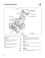
Cub Cadet 524 SWE Two-Stage Snow Thrower 524 WE Operator's Manual - Page 11
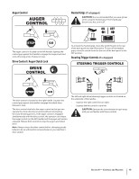
Auger Control
 |
View all Cub Cadet 524 SWE Two-Stage Snow Thrower manuals
Add to My Manuals
Save this manual to your list of manuals |
Page 11 highlights
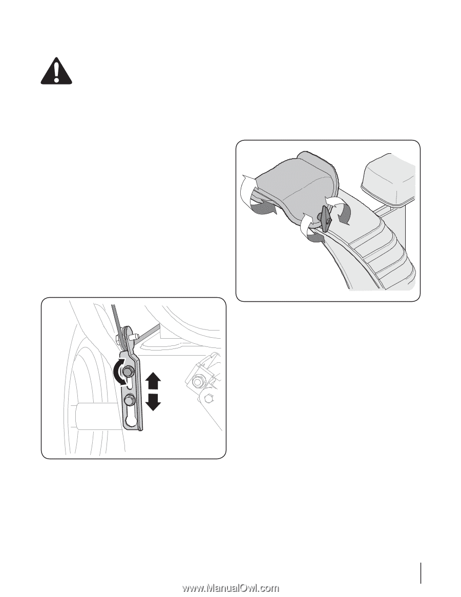
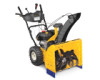
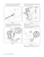
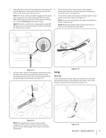
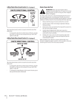
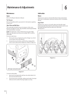
Auger Control WARNING! Prior to operating your snow thrower, carefully read and follow all instructions below. Perform all adjustments to verify your snow thrower is operating safely and properly. Check the adjustment of the auger control as follows: 1. When the auger control is released and in the disengaged "up" position, the cable should have very little slack. It should NOT be tight. 2. In a well-ventilated area, start the snow thrower engine. Refer to the Engine Operator's Manual packed with your snow thrower. 3. While standing in the operator's position (behind the snow thrower), engage the auger. 4. Allow the auger to remain engaged for approximately ten (10) seconds before releasing the auger control. Repeat this several times. 5. With the throttle control in the FAST (rabbit) position and the auger control in the disengaged "up" position, walk to the front of the machine. 6. Confirm that the auger has completely stopped rotating and shows NO signs of motion. If the auger shows ANY signs of rotating, immediately return to the operator's position and shut off the engine. Wait for ALL moving parts to stop before re-adjusting the auger control. 7. To readjust the control cable, loosen the upper hex screw on the auger cable bracket. See Figure 3-14. Chute Assembly NOTE: Upper chutes on models with 4-Way Chute Control are also controlled by the Chute Directional Control. See Figure 4-1. The distance snow is thrown can be adjusted by changing the angle of the chute assembly. To do so: 1. Stop the engine. Refer to the Engine Operator's Manual. Remove the key from the engine and loosen the plastic knob found on the left side of the chute assembly. 2. Pivot the chute upward or downward before retightening the wing knob. See Figure 3-15. Figure 3-15 3. Insert Key into engine and start engine. Refer to the Engine Operator's manual. Figure 3-14 8. Position the bracket upward to provide more slack (or downward to increase cable tension). 9. Retighten the upper hex screw. 10. Repeat steps 2 through 6 above to verify proper adjustment has been achieved. Section 3 - Assembly & Set-Up 11
-
 1
1 -
2
-
3
-
4
-
5
-
 6
6 -
 7
7 -
 8
8 -
 9
9 -
 10
10 -
 11
11 -
 12
12 -
 13
13 -
 14
14 -
 15
15 -
 16
16 -
17
-
18
-
19
-
20
-
21
-
22
-
23
-
24
-
25
-
26
-
27
-
28
 |
 |