CyberPower CP1000AVRLCD User Manual
CyberPower CP1000AVRLCD Manual
 |
View all CyberPower CP1000AVRLCD manuals
Add to My Manuals
Save this manual to your list of manuals |
CyberPower CP1000AVRLCD manual content summary:
- CyberPower CP1000AVRLCD | User Manual - Page 1
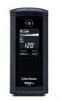
ALLY IN POWER INTELLIGENT UPS SERIES CP850/1000/1350/1500AVRLCD USER MANUAL 10 12 10 9 12 1 2 12 3 10 9 11 8 13 9 11 13 8 11 13 13 8 4 5 6 6 7 7 6 7 CP850/1000AVRLCD CP1350AVRLCD CP1500AVRLCD FEATURES 1. Power Switch 2. Power On Indicator 3. LCD Module Display 4. Display - CyberPower CP1000AVRLCD | User Manual - Page 2
you to free technical support. Register your product now to receive the benefits of CyberPower ownership. IMPORTANT SAFETY WARNINGS (SAVE THESE INSTRUCTIONS) This manual contains important safety instructions. Please read and follow all instructions carefully during installation and operation - CyberPower CP1000AVRLCD | User Manual - Page 3
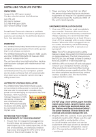
manual (c) USB A+B type cable (d) Function Setup Guide PowerPanel® Personal software sump pump or other large electrical device into the "Battery and Surge Protected Outlets". The power demands of these fuse or circuit breaker and does not service equipment with large electrical demands (e.g. air - CyberPower CP1000AVRLCD | User Manual - Page 4
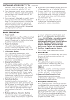
LCD screen will stop flashing. For more information, please refer to the Function Setup Guide 6. Battery and Surge Protected Outlets The UPS has battery ) This LED indicator will illuminate to warn the user that a wiring problem exists, such as bad ground, missing ground or reversed wiring. If this - CyberPower CP1000AVRLCD | User Manual - Page 5
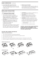
UPS without blocking adjacent outlets. REPLACING THE BATTERY Replacement of batteries located in an OPERATOR ACCESS AREA 1. When replacing batteries, replace with the same number of the following battery: CyberPower / RB1290 for the CP850/1000AVRLCD; CyberPower / RB1290X2 for the CP1350/1500AVRLCD - CyberPower CP1000AVRLCD | User Manual - Page 6
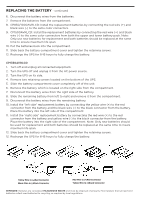
wire (+) to the red connector from the battery and yellow wire (-) to the black connector from the battery. Place the battery into the right side of the compartment. Note: Only new batteries should be used for replacement and both batteries should be replaced at the same time to insure maximum life - CyberPower CP1000AVRLCD | User Manual - Page 7
a problem with the UPS. Contact CyberPower Systems for further help and support. E01: Charger Fault - Overcharge (Contact CyberPower Systems for support.) E02: Charger Fault - No Charge (Contact CyberPower Systems for support.) E11: Battery Overvoltage (Contact CyberPower Systems for support.) E21 - CyberPower CP1000AVRLCD | User Manual - Page 8
TROUBLESHOOTING Problem Possible Cause Circuit breaker button is projecting from the . The battery is worn out. Contact CyberPower Systems about replacement batteries at: cyberpowersystems.com/support. Mechanical problem. Contact CyberPower Systems at: cyberpowersystems.com/support. The - CyberPower CP1000AVRLCD | User Manual - Page 9
TECHNICAL SPECIFICATIONS Model CP850AVRLCDa CP1000AVRLCDa CP1350AVRLCDa CP1500AVRLCDa Capacity 850VA / 510W 1000VA / 600W 1350VA / 815W 1500VA / 900W Nominal Input Voltage 120Vac Input Frequency 60 Hz ± 3 Hz On-Battery Output Voltage Max. Load for UPS Outlets (5 Outlets) Max. Load for - CyberPower CP1000AVRLCD | User Manual - Page 10
not installed and used in accordance with the instructions, may cause harmful interference to radio communications. CyberPower at: Cyber Power Systems (USA), Inc. 4241 12th Ave E., STE 400, Shakopee, MN 55379; call us at (877) 297-6937; or submit a web ticket online at cyberpowersystems.com/support
-
 1
1 -
 2
2 -
 3
3 -
 4
4 -
 5
5 -
 6
6 -
 7
7 -
8
-
9
-
10
 |
 |

INTELLIGENT UPS SERIES
CP850/1000/1350/1500AVRLCD
USER MANUAL
YOUR ULTIMATE ALLY IN POWER
Cyber Power Systems (USA), Inc.
4241 12th Avenue East, Suite 400
|
Shakopee, MN 55379
|
CyberPowerSystems.com
FEATURES
1. Power Switch
2. Power On Indicator
3. LCD Module Display
4. Display/Select Button
5. Mute/Enter Button
6. Battery and Surge Protected Outlets
7. Full-Time Surge Protection Outlets
8. Circuit Breaker
9. DB9/USB Ports
10. Communication Protection Ports
11. Wiring Fault Indicator (red)
12. Coax/Cable/DSS Surge Protection
13. Widely-spaced Outlets
CP850/1000AVRLCD
CP1350AVRLCD
CP1500AVRLCD
1
2
3
4
5
12
9
11
8
10
6
7
10
9
11
13
13
13
13
8
12
6
7
12
9
11
8
10
6
7