CyberPower CP1000PFCLCDTAA User Manual
CyberPower CP1000PFCLCDTAA Manual
 |
View all CyberPower CP1000PFCLCDTAA manuals
Add to My Manuals
Save this manual to your list of manuals |
CyberPower CP1000PFCLCDTAA manual content summary:
- CyberPower CP1000PFCLCDTAA | User Manual - Page 1
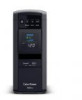
YOUR ULTIMATE ALLY IN POWER PFC SINEWAVE UPS SERIES CP850PFCLCD/CP1000PFCLCDTAA USER MANUAL FEATURES 1. Power Switch 2. Power On Indicator 3. LCD Module Display 4. Down/Display Button 5. Up/Mute Button 6. Enter/Setup Button 7. USB charging ports (Except for CP850PFCLCD) 8. Battery - CyberPower CP1000PFCLCDTAA | User Manual - Page 2
you to free technical support. Register your product now to receive the benefits of CyberPower ownership. IMPORTANT SAFETY WARNINGS (SAVE THESE INSTRUCTIONS) This manual contains important safety instructions. Please read and follow all instructions carefully during installation and operation - CyberPower CP1000PFCLCDTAA | User Manual - Page 3
User's manual (c) USB A+B Type cable (d) Function Setup Guide PowerPanel® Personal software is available on our website. Please visit www.cyberpowersystems.com and go to the Software Section for a free download. SUPPORTS Active PFC POWER SUPPLIES This CyberPower UPS system supports - CyberPower CP1000PFCLCDTAA | User Manual - Page 4
INSTALLING YOUR UPS SYSTEM - continued wall branch outlet is protected by a fuse or circuit breaker and does not service equipment with large electrical demands (e.g. air conditioner, refrigerator, copier, etc.). The warranty prohibits the use of extension cords, outlet strips, and surge strips in - CyberPower CP1000PFCLCDTAA | User Manual - Page 5
more information about the Down/Display Button, please refer to the Function Setup Guide. 5. Up/Mute Button Short press the button to scroll up the function This LED indicator will illuminate to warn the user that a wiring problem exists, such as bad ground, missing ground or reversed wiring. If - CyberPower CP1000PFCLCDTAA | User Manual - Page 6
REPLACING THE BATTERY Replacement of batteries located in an OPERATOR ACCESS AREA 1. When replacing batteries, replace with the same number of the following battery: CyberPower / RB1290 for the CP850PFCLCD / CP100PFCLCD. 2. CAUTION! Risk of Energy Hazard, 12 V, maximum 9 Ampere-hour battery. Before - CyberPower CP1000PFCLCDTAA | User Manual - Page 7
for support.) E02: Charger Fault - No Charge (Contact CyberPower Systems for support.) E11: Battery Overvoltage (Contact CyberPower Systems for support.) E21 appears whenever the UPS is in silent mode. However, when there is a problem with the UPS, the alarm will still beep even in silent mode. 11. - CyberPower CP1000PFCLCDTAA | User Manual - Page 8
about functions setup, please refer to the Function Setup Guide. TROUBLESHOOTING Problem Circuit breaker button is projecting from the back of plugged in. Contact CyberPower Systems about replacement batteries at: cyberpowersystems.com/support. Turn the UPS off. Wait 10 seconds and then turn the - CyberPower CP1000PFCLCDTAA | User Manual - Page 9
TROUBLESHOOTING Problem PowerPanel® is inactive (all icons are gray). The USB power ports USB power port and then turn the UPS on. Additional troubleshooting information can be found at "Support" at www.CyberPowerSystems.com TECHNICAL SPECIFICATIONS Model CP850PFCLCDa CP1000PFCLCDa Capacity - CyberPower CP1000PFCLCDTAA | User Manual - Page 10
if not installed and used in accordance with the instructions, may cause harmful interference to radio communications. However, (877) 297-6937; or submit a web ticket online at cyberpowersystems.com/support. Cyber Power Systems (USA), Inc. encourages environmentally sound methods for disposal and
-
 1
1 -
 2
2 -
 3
3 -
 4
4 -
 5
5 -
 6
6 -
 7
7 -
8
-
9
-
10
 |
 |

PFC SINEWAVE UPS SERIES
CP850PFCLCD/CP1000PFCLCDTAA
USER MANUAL
YOUR ULTIMATE ALLY IN POWER
Cyber Power Systems (USA), Inc.
4241 12th Avenue East, Suite 400
|
Shakopee, MN 55379
|
CyberPowerSystems.com
FEATURES
1. Power Switch
2. Power On Indicator
3. LCD Module Display
4. Down/Display Button
5. Up/Mute Button
6. Enter/Setup Button
7. USB charging ports
(Except for CP850PFCLCD)
8. Battery and Surge Protected Outlets
9. Full-time Surge Protected Outlets
10. Circuit Breaker
11. DB9/USB Ports to PC
12. Wiring Fault Indicator (red)
13. Communication Protection Ports
(RJ45)