CyberPower CP750LCD User Manual
CyberPower CP750LCD Manual
 |
View all CyberPower CP750LCD manuals
Add to My Manuals
Save this manual to your list of manuals |
CyberPower CP750LCD manual content summary:
- CyberPower CP750LCD | User Manual - Page 1
. CAUTION! Risk of explosion if battery is replaced by an incorrect type. Batteries shall be installed by service personnel, and the replacement of batteries with a suitable recommended type. Dispose of used batteries according to the instructions. CAUTION! Do not dispose of batteries in a fire. The - CyberPower CP750LCD | User Manual - Page 2
within ten days of the occurrence. What Will We Do To Correct Problems? CyberPower will inspect and examine the Product. If the Product is defective in material or workmanship, CyberPower will repair or replace it at CyberPower's expense, or, if CyberPower is unable to or decides not to repair or
-
 1
1 -
 2
2
 |
 |

CP750LCD/CP750LCDM
User’s Manual
K01-0000121-01
(SAVE THESE INSTRUCTIONS)
This manual contains important safety instructions. Please read and follow all instructions carefully during installation and operation of the unit.
Read this manual thoroughly before attempting to unpack, install, or operate your UPS.
CAUTION!
To prevent the risk of fire or electric shock, install in a temperature and humidity controlled indoor area free of conductive
contaminants.
(Please see specifications for acceptable temperature and humidity range).
CAUTION!
To reduce the risk of electric shock, do not remove the cover. There are no user serviceable parts inside.
CAUTION!
Hazardous live parts inside can be energized by the battery even when the AC input power is disconnected.
CAUTION!
The
UPS must be connected to an AC power outlet with fuse or circuit breaker protection.
Do not plug into an outlet that is not
grounded.
If you need to de-energize this equipment, turn off and unplug the unit.
CAUTION!
To avoid electric shock, turn off the unit and unplug it from the AC power source before installing a computer component.
CAUTION!
Not for use in a computer room as defined in the Standard for the Protection of Electronic Computer/Data Processing Equipment,
ANSI/NFPA 75.
CAUTION!
To reduce the risk of fire, connect only to a circuit provided with 20 amperes maximum branch circuit over current protection in
accordance with the National Electric Code, ANSI/NFPA 70.
CAUTION!
Risk of explosion if battery is replaced by an incorrect type. Batteries shall be installed by service personnel, and the replacement of
batteries with a suitable recommended type. Dispose of used batteries according to the instructions.
CAUTION!
Do not dispose of batteries in a fire. The batteries may explode.
CAUTION!
Do not open or mutilate batteries. Released electrolyte is harmful to the skin and eyes. It may be toxic.
DO NOT USE FOR MEDICAL OR LIFE SUPPORT EQUIPMENT!
CyberPower Systems does not sell products for life support or medical
applications.
DO NOT
use in any circumstance that would affect operation and safety of life support equipment, any medical applications or
patient care.
DO NOT USE WITH OR NEAR AQUARIUMS!
To reduce the risk of fire or electric shock, do not use with or near an aquarium.
Condensation
from the aquarium can cause the unit to short out.
UNPACKING
Inspect the UPS upon receipt. The box should contain the following:
(a) UPS unit (b) User’s manual (c) PowerPanel
®
Personal Edition software CD
(d) USB device cable (e) Telephone cable (f) Warranty registration card
HOW TO DETERMINE THE POWER REQUIREMENTS OF YOUR EQUIPMENT
1.
Ensure that the equipment plugged into the outlet does not exceed the UPS unit’s rated capacity (750VA/420W for CP750LCD/CP750LCDM).
If the rated capacities of the unit are exceeded, an overload condition may occur and cause the UPS unit to shut down or the circuit breaker to
trip.
2.
There are many factors that can affect the amount of power that your computer system will require.
For optimal system performance keep
the load below 80% of the unit’s rated capacity.
HARDWARE INSTALLATION GUIDE
1. Your new UPS may be used immediately upon receipt. However, after receiving a new UPS, to
ensure the battery’s maximum charge capacity, it is recommended that you charge the battery
for at least 8 hours. Your UPS is equipped with an auto-charge feature. When the UPS is
plugged into an AC outlet, the battery will automatically charge when it’s turned on or turned off.
2. With the UPS unit turned off and unplugged, connect your computer, monitor, and any other
peripherals requiring battery backup from the SURGE/BATTERY outlets.
Plug the other peripheral equipment (eg. printer, scanner,
speakers, etc.) into the full-time surge protection outlets.
DO NOT plug a laser printer, paper shredder, copier, space heater, vacuum,
sump pump, or other large electrical device into the “Battery and Surge Protected Outlets”. The power demands of these devices
will overload and possibly damage the unit.
3. To protect a fax, phone, or modem, connect a telephone cable from the wall jack outlet to the IN jack
of the UPS. Connect a telephone cable from one of the UPS OUT jacks to the modem port on the computer.
The other UPS OUT jack can be used to protect a telephone or fax machine.
4. Plug the UPS into a 2 pole, 3 wire grounded receptacle (wall outlet).
Make sure the wall branch outlet is
protected by a fuse or circuit breaker and does not service equipment with large electrical demands (e.g. air
conditioner, refrigerator, copier, etc.).
The warranty prohibits the use of extension cords, outlet strips,
and surge strips.
5. Press the power switch to turn the unit on.
The Power On indicator light will illuminate green and the unit will “beep” twice.
6. If an overload is detected, an audible alarm will sound and the unit will emit one long beep.
To correct this, turn the UPS off and unplug at
least one piece of equipment from the battery power supplied outlets.
Make sure the circuit breaker is depressed and then turn the UPS on.
7. To maintain optimal battery charge, leave the UPS plugged into an AC outlet at all times.
8. To store the UPS for an extended period, cover it and store with the battery fully charged.
While in storage, recharge the battery every three
months to ensure optimal battery life.
9. Insure the wall outlet and UPS are located near the equipment being attached for proper accessibility.
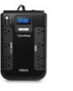
DESCRIPTION
ゼ
Battery and Surge Protected Outlets
The unit has four battery powered/surge suppression outlets to ensure temporary uninterrupted operation of your equipment during a power
failure.
(DO NOT plug a laser printer, paper shredder, copier, space heater, vacuum, sump pump, or other large electrical device
into the “Battery and Surge Protected Outlets.” The power demands of these devices will overload and possibly damage the unit.)
ソ
Full-Time Surge Protection Outlets
The unit has four surge suppression outlets.
ゾ
Power Switch
Press the power button to turn the UPS on or off.
タ
Power On Indicator (green)
This LED is illuminated when the utility power is normal and the UPS outlets are providing power, free of surges and spikes.
ダ
Electrical Wiring Fault Indicator (red)
This LED indicator will illuminate to warn the user that a wiring problem exists, such as bad ground, missing ground or reversed wiring.
If
this is illuminated, disconnect all electrical equipment from the outlet and have an electrician verify the outlet is properly wired. The unit will
not provide surge protection without being plugged into a grounded and properly wired wall outlet.
チ
Communication Protection Ports
Communication protection ports will protect any standard modem, fax, or telephone line. (RJ11)
ヂ
Circuit Breaker
Located on the side of the UPS, the circuit breaker serves to provide overload and fault protection.
ッ
USB Port to PC
The USB port allows connection and communication between the USB port on the computer and the UPS unit.
The UPS communicates its
status to the PowerPanel
®
Personal Edition software.
The USB interface is also compatible with the Power Management applications
provided by Windows 7, Vista, Mac OS X, and Linux.
ツ
Outlets Designed for AC Adapters
The UPS unit has four widely-spaced outlets, so AC power adapters can be plugged into the UPS without overlapping adjacent outlets.
INPUT voltage meter:
This meter measures the AC voltage that the UPS system is receiving from the
utility wall outlet. The UPS is designed to continuously supply connected equipment with stable,
110/120 output voltage. In the event of a complete power loss, severe brownout, or over-voltage, the
UPS relies on its internal battery to supply consistent 110/120 output voltage. The INPUT voltage
meter can be used as a diagnostic tool to identify poor-quality input power.
OUTPUT voltage meter:
This meter measures, in real time, the AC voltage that the UPS system is
providing to the computer during normal AC/Utility Power mode, and battery backup mode.
ESTIMATE RUN TIME:
This displays the run time estimate of the UPS with the current battery
capacity and load.
NORMAL icon
: This icon appears when the UPS is working under normal conditions.
BATTERY icon
: During a severe brownout or blackout, this icon appears and an alarm sounds (two short beeps followed by a pause) to indicate
the UPS is operating from its internal battery. During a prolonged brownout or blackout, the alarm will sound continuously. The BATT.CAPACITY
meter will show one 20% capacity segment remaining to indicate the UPS's battery is nearly out of power. You should save files and turn off your
equipment immediately.
OVER LOAD icon
: This icon appears and an alarm sounds to indicate the battery-supplied outlets are overloaded. To clear the overload, unplug
some of your equipment from the battery-supplied outlets until the icon turns off and the alarm stops.
BATT. CAPACITY meter
: This meter displays the approximate charge level of the UPS's internal battery in 20% increments. During a blackout
or severe brownout, the UPS switches to battery power (the BATTERY icon appears) and the battery charge level decreases.
LOAD CAPACITY meter
: This meter displays the approximate output load level of the UPS battery outlets in 20% increments.
AC/Utility Mode
Select SW
Press
UPS Status Display
Capacity Display
Digital Value Display
Load
Cap.
Battery
Cap.
Input
Voltage
Output
Voltage
Run
Time
%
of Load
%
of Batt.
Initial
V
X
X
--
V
X
V
1st
V
X
X
--
V
X
V
2nd
V
X
X
--
V
X
V
3rd
V
X
X
--
V
X
V
4th
V
X
X
--
X
V
V
5th(Return)
V
X
X
--
V
X
V
(Overload)
V
X
X
V
--
--
--
--
--
--
--
“V” : light up,
“X” : go out,
“--“ : not available
Battery mode
“V” : light up,
“X” : go out,
“--“ : not available
Problem
Possible Cause
Solution
Full-time surge protection outlets
stop providing power to
equipment. Circuit breaker
button is projecting from the side
of the unit.
Circuit breaker has tripped due to an
overload.
Turn the UPS off and unplug at least one piece of
equipment.
Wait 10 seconds, reset the circuit breaker by
depressing the button, and then turn the UPS on.
The UPS does not perform
expected runtime.
Battery not fully charged.
Recharge the battery by leaving the UPS plugged in.
Battery is worn out.
Contact CyberPower Systems about replacement batteries
at
The UPS will not turn on.
The on/off switch is designed to
prevent damage from rapidly turning
it off and on.
Turn the UPS off.
Wait 10 seconds and then turn the UPS
on.
The unit is not connected to an AC
outlet.
The unit must be connected to a 110/120V 50/60Hz outlet.
The battery is worn out.
Contact CyberPower Systems about replacement batteries
at
Mechanical problem.
Contact CyberPower Systems at
Select SW
Press
UPS Status Display
Capacity Display
Digital Value Display
Load
Cap.
Battery
Cap.
Input
Voltage
Output
Voltage
Run
Time
%
of Load
%
of Batt.
Initial
X
V
--
--
X
V
V
1st
X
V
--
--
X
V
V
2nd
X
V
--
--
V
X
V
3rd
X
V
--
--
X
V
V
4th
X
V
--
--
X
V
V
5th(Return)
X
V
--
--
X
V
V
Press >3sec
(Sound
Disable)
X
V
V
--
--
--
--
--
--
--
--
Press >3sec
again
(Sound Enable)
X
V
X
--
--
--
--
--
--
--
--
(Overload)
X
V
--
V
--
--
--
--
--
--
--
BASIC OPERATION
INSTALLING YOUR UPS SYSTEM
TROUBLESHOOTING
IMPORTANT SAFETY WARNINGS
DEFINITIONS FOR ILLUMINATED LCD INDICATORS
The LCD display indicates a variety
of UPS operational conditions. All
descriptions apply when the UPS is
plugged into an AC outlet and turned
on or when the UPS is on battery.