CyberPower CP850PFCLCD User Manual
CyberPower CP850PFCLCD Manual
 |
View all CyberPower CP850PFCLCD manuals
Add to My Manuals
Save this manual to your list of manuals |
CyberPower CP850PFCLCD manual content summary:
- CyberPower CP850PFCLCD | User Manual - Page 1
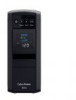
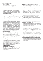
ALLY IN POWER PFC SINEWAVE UPS SERIES CP850PFCLCD / CP1000PFCLCD USER MANUAL FEATURES 1. Power Switch 2. Power On Indicator 3. LCD Module Display 4. Down/Display Button 5. Up/Mute Button 6. Enter/Setup Button 7. USB charge ports (Except for CP850PFCLCD) 8. Battery and Surge Protected Outlets - CyberPower CP850PFCLCD | User Manual - Page 2
you to free technical support. Register your product now to receive the benefits of CyberPower ownership. IMPORTANT SAFETY WARNINGS (SAVE THESE INSTRUCTIONS) This manual contains important safety instructions. Please read and follow all instructions carefully during installation and operation - CyberPower CP850PFCLCD | User Manual - Page 3
unit (b) User's manual (c) USB A+B Type cable (d) Function Setup Guide PowerPanel® software is available on our website. Please visit www.cyberpowersystems. com and go to the Software Section for a free download. SUPPORTS ACTIVE PFC POWER SUPPLIES This CyberPower UPS system supports High Efficiency - CyberPower CP850PFCLCD | User Manual - Page 4
breaker and does not service equipment with large electrical demands battery fully charged. While in storage, recharge the battery every three months to ensure optimal battery life. 7. Ensure the wall outlet and UPS are located near the equipment being attached for proper accessibility. CYBERPOWER - CyberPower CP850PFCLCD | User Manual - Page 5
information please review the " Setup Button, please refer to the Function Setup Guide. 7. USB charge ports (Except for CP850PFCLCD) The USB Power ports (Type A and Type C) provide DC 5V 3.1A power output with battery backup. 8. Battery the user that a wiring problem exists, such as bad ground - CyberPower CP850PFCLCD | User Manual - Page 6
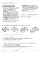
in an OPERATOR ACCESS AREA 1. When replacing batteries, replace with the same number of the following battery: CyberPower / RB1290 for the CP850PFCLCD / CP1000PFCLCD. 2. CAUTION! Risk of Energy Hazard, 24 V, maximum 9 Ampere-hour battery. Before replacing batteries, remove conductive jewelry such as - CyberPower CP850PFCLCD | User Manual - Page 7
is a problem with the UPS. Press the POWER button to turn the UPS off. E01: Charger Fault - Overcharge (Contact CyberPower Systems for support.) E02: Charger Fault - No Charge (Contact CyberPower Systems for support.) E11: Battery Overvoltage (Contact CyberPower Systems for support.) E21: Output - CyberPower CP850PFCLCD | User Manual - Page 8
Battery Mode more often. For more information about functions setup, please refer to the Function Setup Guide. TROUBLESHOOTING Problem . Contact CyberPower Systems about replacement batteries at: cyberpowersystems.com/support. Contact CyberPower Systems at: cyberpowersystems.com/support. Connect - CyberPower CP850PFCLCD | User Manual - Page 9
port and then turn the UPS on. Additional troubleshooting information can be found at "Support" at www.CyberPowerSystems.com TECHNICAL SPECIFICATIONS Model CP850PFCLCDa CP1800PFCLCDa Capacity Nominal Input Voltage Input Frequency On-Battery Output Voltage Max. Load for UPS Outlets (5 Outlets - CyberPower CP850PFCLCD | User Manual - Page 10
not installed and used in accordance with the instructions, may cause harmful interference to radio communications. CyberPower at: Cyber Power Systems (USA), Inc. 4241 12th Ave E., STE 400, Shakopee, MN 55379; call us at (877) 297-6937; or submit a web ticket online at cyberpowersystems.com/support
-
 1
1 -
 2
2 -
 3
3 -
 4
4 -
 5
5 -
 6
6 -
 7
7 -
8
-
9
-
10
 |
 |

PFC SINEWAVE UPS SERIES
CP850PFCLCD / CP1000PFCLCD
USER MANUAL
YOUR ULTIMATE ALLY IN POWER
Cyber Power Systems (USA), Inc.
4241 12th Avenue East, Suite 400
|
Shakopee, MN 55379
|
CyberPowerSystems.com
FEATURES
1. Power Switch
2. Power On Indicator
3. LCD Module Display
4. Down/Display Button
5. Up/Mute Button
6. Enter/Setup Button
7. USB charge ports
(Except for CP850PFCLCD)
8. Battery and Surge Protected Outlets
9. Full-Time Surge Protection Outlets
10. Circuit Breaker
11. Serial / USB Ports to PC
12. Wiring Fault Indicator (red)
13. Communication Protection Ports (RJ45)