D-Link DCS-5222L User Manual - Page 64
Technical Specifications - I/O Terminal Application
 |
View all D-Link DCS-5222L manuals
Add to My Manuals
Save this manual to your list of manuals |
Page 64 highlights
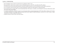
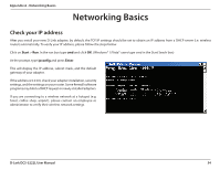
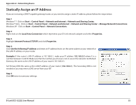
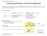
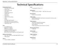
Appendix A - Technical Specifications Technical Specifications - I/O Terminal Application Typically used in association with programming scripts for developing applications for motion detection, event triggering, alarm notification via e-mail, and a variety of external control functions. The 4-pin I/O Terminal Block is located on the rear panel and provides the interface of a photo-coupled switch output and a photo-coupled input. Connector Pin Assignment Sign DO- DO+ DIDI+ FUNCTION Photo-Relay OUTPUT (Normal Open) Photo-Relay OUTPUT(Common) Photo-Relay INPUT (-) Photo-Relay INPUT (+) SPECIFICATION Close circuit current max. 70 mA AC, or 100 mA DC. On-Resistance max. 30 Ohm. Open circuit blocking voltage max. 240VAC or 340VDC Active High voltage 2.5~25VDC Inactive Dropout voltage 0~1.5 VDC Internal on-current has limit at 7mA to protect the photo-relay. Monitoring and Controlling By entering http requests in your browser's URL field, it is possible to: • Monitor the status of digital input. • Drive the output switch on or off. Interface Schematic Output device (load) is driven by an external AC or DC power supply. DO- AC/ DC Load DO+ Input device (active control device) has an independent power supply. D-Link DCS-5222L User Manual 58
-
 1
1 -
2
-
3
-
4
-
5
-
6
-
7
-
8
-
9
-
10
-
11
-
12
-
13
-
14
-
15
-
16
-
17
-
18
-
19
-
20
-
21
-
22
-
23
-
24
-
25
-
26
-
27
-
28
-
29
-
30
-
31
-
32
-
33
-
34
-
35
-
36
-
37
-
38
-
39
-
40
-
41
-
42
-
43
-
44
-
45
-
46
-
47
-
48
-
49
-
50
-
51
-
52
-
53
-
54
-
55
-
56
-
57
-
58
-
 59
59 -
 60
60 -
 61
61 -
 62
62 -
 63
63 -
 64
64 -
 65
65 -
 66
66
 |
 |