D-Link DE-1824EI User Guide
D-Link DE-1824EI - Hub - EN Manual
 |
UPC - 790069217593
View all D-Link DE-1824EI manuals
Add to My Manuals
Save this manual to your list of manuals |
D-Link DE-1824EI manual content summary:
- D-Link DE-1824EI | User Guide - Page 1
10BASE-T Stackable Hubs Intelligent Series User's Guide Rev. 02w (Oct., 2004) 6SNMPT....01 Printed In Taiwan RECYCLABLE - D-Link DE-1824EI | User Guide - Page 2
10BASE-T Stackable Hubs FCC Warning This equipment has been tested and found to comply with radiate radio frequency energy and, if not installed and used in accordance with this user's guide, may cause harmful interference to radio communications. Operation of this equipment in a residential area - D-Link DE-1824EI | User Guide - Page 3
10BASE-T Stackable Hubs TABLE OF CONTENTS 0 ABOUT THIS GUIDE vi Overview of the User's Guide vi 1 INTRODUCTION 1-1 Overview 1-1 Back Panel Layouts 2-1 Front Panel Indicators 2-3 3 SETTING UP THE HUB 3-1 Power and Environmental Requirements 3-1 Power Connection 3-2 Free-standing Installation - D-Link DE-1824EI | User Guide - Page 4
Cascading 5-6 6 USING THE CONSOLE INTERFACE 6-1 Connecting to the Hub 6-1 Console Usage Conventions 6-2 Logging in to the Hub Console 6-3 Logging In...6-3 Changing your Password 6-5 Setting up the Master Hub 6-6 TCP/IP Settings 6-6 Out-of-band management and console settings 6-9 Software - D-Link DE-1824EI | User Guide - Page 5
Stack Configuration 6-16 Primary and Backup Master Hubs 6-16 Controlling Hubs in the Hub Stack 6-17 Controlling Individual Ports 6-19 Segmenting Hubs 6-23 Monitoring the Hub Stack 6-24 Displaying Segment, Group, and Port Statistics 6-21 Displaying Node Tracking Information 6-28 Resetting the - D-Link DE-1824EI | User Guide - Page 6
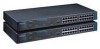
. This series includes: ♦ the 12/24-port stackable managed master hub, and ♦ the 12/24-port standard hub. In this User's Guide, the Intelligent Series stackable hubs are frequently described simply as "hub" or "hubs" wherever the text applies to both models. Model numbers are normally used only to - D-Link DE-1824EI | User Guide - Page 7
B. Power-On Self Test Provides information about the POST messages used for troubleshooting problems with the hub. ♦ Appendix C. Boot Configuration File Describes the hub boot configuration file. ♦ Appendix D. Cables and Connectors Describes the specifications of the cables and connectors - D-Link DE-1824EI | User Guide - Page 8
- D-Link DE-1824EI | User Guide - Page 9
connectivity solution by maximizing network performance. Overview Important features of the Intelligent Series include: Media Connection Flexibility The Intelligent Series hubs support multiple Ethernet media types, with twelve or twenty-four ports for twisted-pair cabling, and one AUI port which - D-Link DE-1824EI | User Guide - Page 10
errors. Security The Intelligent Series supports intrusion control. Intrusion Control prevents unauthorized individuals from accessing the network. Through the network management software, Ethernet addresses that represent authorized users can be assigned to each hub port. If a packet is received - D-Link DE-1824EI | User Guide - Page 11
♦ Twisted-pair hub stack daisy chain cabling ◊ Allows a total distance of 100 meters between the first hub and the last hub in the daisy-chain. ◊ Expandable network capacity up to 8 hubs in a single of network status, allowing managers to diagnose and troubleshoot instantly. Introduction 1-3 - D-Link DE-1824EI | User Guide - Page 12
-60Hz) without fuse changes or manual voltage range settings. ♦ Slim Hub IDs are automatically assigned during initialization or when daisy chain links supported.) The RS-232 serial communication port can be configured as either local console or remote access through Telnet based on SLIP support - D-Link DE-1824EI | User Guide - Page 13
10BASE-T Stackable Hubs ♦ Redundant Backup Management ◊ To maximize management uptime, two master hubs can be put in the same stack. If the first one goes down, the backup hub can automatically take over to provide uninterrupted traffic monitoring and network control. Introduction 1-5 - D-Link DE-1824EI | User Guide - Page 14
- D-Link DE-1824EI | User Guide - Page 15
the front panel, rear panel, and display of the stackable hubs. Note that there are variations in the appearances of the front and back panels between hubs in the series. Only the 24-port models are depicted in this User's Guide. Front and Back Panel Layouts LED Panel Uplink Switch 10BASE-T Ports - D-Link DE-1824EI | User Guide - Page 16
found on the front and back panels of the hubs: ♦ Ethernet Ports Used for connecting the hub to network devices using 10BASE-T shielded or unshielded twisted 232 Console Port (manageable models only) Used to connect the master hub to a network management station for outof-band communication, or for - D-Link DE-1824EI | User Guide - Page 17
Daisy-chain Port The daisy-chain port consists of one set of two RJ-45 connectors. It allows you to connect Intelligent hubs together into a stack of up to 8 hubs with a maximum of 192 10BASE-T ports. ♦ Expansion Module Port (manageable models only) Used for adding optional expansion modules to the - D-Link DE-1824EI | User Guide - Page 18
of a port lights green when the port is connected to a powered Ethernet station. If the station to which the hub is connected is powered off, or if there is a problem with the link, the indicator is off. ◊ Receive The indicator of a port blinks green when the port is currently receiving packets on - D-Link DE-1824EI | User Guide - Page 19
10BASE-T Stackable Hubs ◊ Manual Partition The indicator of a port lights amber continually when the port is manually partitioned. Manually partitioning a port has the same effect as automatic partitioning, except that you must also manually re-enable it. You can choose to manually partition a port - D-Link DE-1824EI | User Guide - Page 20
turn on Group ID flashing, which will make the hub ID indicator flash off and on. This may be useful for identifying a specific hub or a hub stack within a large bank of hubs. ♦ Segmented The Segmented indicator lights when the entire hub has been manually segmented off from the rest of the network - D-Link DE-1824EI | User Guide - Page 21
10BASE-T Stackable Hubs connected together into a single Ethernet "collision domain" through the daisy chain connectors on the back. Segmenting a hub places it in its own collision domain, while allowing it to be managed with the rest of the stack. External Features and Indicators 2-7 - D-Link DE-1824EI | User Guide - Page 22
of the network, and may indicate that the network is overloaded or that there is some sort of hardware or wiring problem. The Col Ratio is only displayed on the manageable hub models; on all models, however, the Col indicator will blink when a collision occurs. 2-8 External Features and Indicators - D-Link DE-1824EI | User Guide - Page 23
most countries around the world. Before connecting the supplied power cord to the hub, check to see that the power cord does not exceed the maximum length should conform to the standards of the country where you are using the hub. When using a 230V power source within the U.S., use a UL-listed - D-Link DE-1824EI | User Guide - Page 24
connect power, take the following steps. 1. Plug the female IEC connector of the power cable into the power connector on the back of the hub. 2. Insert the three-pronged plug on the power module cable into a non- switched, grounded power outlet on a wall, a power strip, or a grounded extension cord - D-Link DE-1824EI | User Guide - Page 25
the chassis up-on-end and attach one rubber foot about 1 inch from each corner. Rack-Mounting The hubs can be used standalone on a tabletop or shelf, or mounted in a rack. When mounting the hub stack in a rack, confirm that the rack is an EIA standard 19-inch rack. For rack mounting - D-Link DE-1824EI | User Guide - Page 26
as Media Access Units or MAUs) to be installed partially recessed within the rear panel of the hub. To make inserting and removing the transceiver easier, a transceiver tray has been included with the hub. To install a transceiver using the tray, first place the transceiver in the tray, with the - D-Link DE-1824EI | User Guide - Page 27
replace the power supply. 1. Disconnect the power cord from the AC outlet. 2. Disconnect the power cord from its connector on the rear of the hub. 3. Using a Phillips screwdriver, remove the screws securing the power supply to release the unit. 4. Remove the power supply by sliding it out the rear - D-Link DE-1824EI | User Guide - Page 28
- D-Link DE-1824EI | User Guide - Page 29
to link eight hubs together without violating the repeater count limitation. This chapter tells about the various roles hubs in the stack can play, how to connect the hubs using the Daisy-Chain ports, and how to divide hubs in the stack into separate segments. Hub Roles The series supports both - D-Link DE-1824EI | User Guide - Page 30
connected using the daisy-chain ports located at the rear of the hub. Each hub has an IN port and an OUT port. Hubs are daisychained together by connecting the OUT port of one hub to the IN port of the next hub in the chain. A typical stack arrangement is shown below. Daisy Chain In - D-Link DE-1824EI | User Guide - Page 31
downstream of the Active Master. Otherwise, you will not be able to control or monitor any slave hubs upstream of the master hub. Each master hub has its own IP address. All master hubs respond to SNMP management commands, though only the Active Master is capable of controlling and monitoring other - D-Link DE-1824EI | User Guide - Page 32
Managed hubs. The master hub remembers the Hub ID associated with each hub in the stack, and even if a hub is removed, the other hubs will keep their original Hub IDs. When you add a new hub to the stack, the master hub will assign it an unused Hub ID. Daisy-chaining Hubs into a Hub Stack Hubs are - D-Link DE-1824EI | User Guide - Page 33
to balance network loads, since a smaller number of devices compete for the 10Mbps bandwidth on each network segment. A stack of eight hubs makes network management convenient, but 192 Ethernet stations on a single Ethernet network segment may give slow response at peak network loads. Therefore - D-Link DE-1824EI | User Guide - Page 34
a stack divided into three separate collision domains. Hubs 4 and 5 are isolated from Collision Domain 1 (hubs 1, 2, and 3) using the hub segmentation capability, putting them into their own isolated Collision Domains 2 and 3 respectively. A switch, bridge or router can be used to connect the three - D-Link DE-1824EI | User Guide - Page 35
console interface, see Chapter 6 in this User's Guide. For information about segmenting hubs using the network management module for the hub, see the management module's User's Guide. NOTE: Hub segmentation is controlled by the master hub. While the hub is performing its Power-On Self-Test (POST - D-Link DE-1824EI | User Guide - Page 36
- D-Link DE-1824EI | User Guide - Page 37
on each port means the ports are MDI-X ports, which connect to workstations and servers using straight-through cables and to other hubs using crossover cables. To connect to a network station, use ordinary Ethernet twisted pair cable (Category 3 or better), either directly or through a central - D-Link DE-1824EI | User Guide - Page 38
the other end into a free 10BASE-T port on the front of the hub. When both the hub and the device at the other end of the connection are turned on , and the cable is connected at both ends, then the Link indication for the - D-Link DE-1824EI | User Guide - Page 39
rules in mind. In particular, be sure that there are no more than four repeaters (including hubs or hub stacks) between any two stations on the network. Also, be careful that none of the cable links exceed the maximum length for that type of cable. If you need to exceed the repeater limit - D-Link DE-1824EI | User Guide - Page 40
connect the other end of the cable to an ordinary (non-uplink) port on the other repeater hub or Ethernet switch. Don't try to cascade more than four repeater hub stacks in a line using twisted-pair cabling. Instead, use a multilevel cascading scheme as discussed in the Multilevel Cascading section - D-Link DE-1824EI | User Guide - Page 41
Ethernet (10BASE5) or fiber optic cabling (FOIRL or 10BASEFL) to the hub. A thick Ethernet trunk can be up to 500 meters long (preferably fiber optic transceiver, you can link to another hub or hub stack up 1000 meters away using FOIRL (Fiber Optic Inter-Repeater Link), or up to 2000 meters away - D-Link DE-1824EI | User Guide - Page 42
the network goes through more than four repeaters. For example, a backbone level of hubs can be connected in a bus using 10BASE2 cabling, and second-level workgroup hubs can be connected to the backbone hubs using twisted-pair cabling. This type of network layout allows a greatly expanded number of - D-Link DE-1824EI | User Guide - Page 43
6 6 USING THE CONSOLE INTERFACE Your Intelligent stackable Ethernet hub supports a console management interface that allows you to set up and control your hub, either with an ordinary terminal (or terminal emulator), or over the network using the TCP/IP Telnet protocol. You can use this facility to - D-Link DE-1824EI | User Guide - Page 44
You can also access the same functions over a Telnet interface. Once you have set an IP address for your hub, you can use a Telnet program (in a VT100 compatible terminal mode) to access and control the hub. All of the screens are for the most part identical, whether accessed from the console port - D-Link DE-1824EI | User Guide - Page 45
, you will need to first log into the hub, giving a password. This section tells how to log onto the hub, and how to change your password. Logging In When you first connect to the hub, it will display the login screen: Figure 6 -1 Login Screen To log in, 1. Type in your user name and press Enter - D-Link DE-1824EI | User Guide - Page 46
will be displayed. NOTE: When the hub is shipped from the factory, the default user name is SNMP-T and the default password is also SNMP-T. You will need to use this user name and password when you first set up your hub or if you have completely reset the hub settings using the Factory Reset NVRAM - D-Link DE-1824EI | User Guide - Page 47
-T Stackable Hubs Changing your Password To change your user password: 1. Choose User Account Change from the main menu. 2. Choose Change Password. Figure 6 -3 Change Password 1. Type in your user name and press Enter. 2. Type in your old password and press Enter. 3. Type in the new password you - D-Link DE-1824EI | User Guide - Page 48
password. Setting up the Master Hub This section describes the settings you will need to change to allow you to be able to manage the hub is restarted. Fields that can be set include: ♦ IP Address: determines the IP address used by the hub for receiving SNMP and Telnet communications. Should be of - D-Link DE-1824EI | User Guide - Page 49
10BASE-T Stackable Hubs ♦ Default Gateway: IP address that determines where frames with a destination outside the current subnet should be sent. This is usually the address of a router or a host acting as an IP gateway. If your network is not part of an internetwork, or you do not want the hub to be - D-Link DE-1824EI | User Guide - Page 50
and console settings You can use the Out-of-Band/Console Setting menu to choose whether to use the hub's RS-232C serial port for console management or for out-of-band TCP/IP communications using SLIP, and to set the bit rate used for SLIP communications. The following fields can be - D-Link DE-1824EI | User Guide - Page 51
Out-of-Band/Console Setting Menu Software Updates The hub is capable of obtaining its boot-time configuration information, The fields you can set in this menu are: ♦ Software Update Determines whether or not the hub will try to look for a configuration file over the network. If set to Disable, none - D-Link DE-1824EI | User Guide - Page 52
Hubs ♦ Boot Server IP Address The IP address of the TFTP server where the configuration file is located. This entry is used only if the S/W Update Control is enabled and your boot protocol is tftp only; if you are using bootp-tftp mode, or if Send BOOTP Request on Power Up is enabled, the address - D-Link DE-1824EI | User Guide - Page 53
64 characters: ♦ System Name: corresponds to the SNMP MIB II variable system.sysName, and is used to give a name to the hub for administrative purposes. The hub's fully qualified domain name is often used, provided a name has been assigned. ♦ System Location: corresponds to the SNMP MIB II variable - D-Link DE-1824EI | User Guide - Page 54
request is made using an unknown community name. The hub allows traps to be routed to up to four different network management hosts. Figure 6 -8 SNMP Trap Manager Menu The following trap parameters can be set: ♦ IP Address: gives the IP address of the network management station to receive the trap - D-Link DE-1824EI | User Guide - Page 55
is an arbitrary string of characters used as a "password" to control access to the hub. If the hub receives a request with a community name it doesn't only or read/write. The community names public and private are defined by default; you can change these names in addition to adding others. You will - D-Link DE-1824EI | User Guide - Page 56
10BASE-T Stackable Hubs Adding and Deleting Users Access to the console, whether using the console port or via Telnet, is controlled using a user name and password. Up to three of these user names can be defined. One user, named SNMP, is defined by default; this user name can be removed if desired. - D-Link DE-1824EI | User Guide - Page 57
10BASE-T Stackable Hubs Figure 6 -11 Create New User 1. Choose SAVE and press Enter to let the user addition take effect. 2. Choose EXIT to leave the Create New User - D-Link DE-1824EI | User Guide - Page 58
Enter to let the user addition take effect. 2. Choose EXIT to leave the Delete Users menu. Hub Stack Configuration Several important hub parameters useful in the day-to-day management of the hub can be viewed and controlled using the Group Configuration, Primary/Backup Master Menu, and Port State - D-Link DE-1824EI | User Guide - Page 59
found within the Network Monitoring menu, displays information about each of the hubs in the stack, and allows you to make the Hub ID indicator flash. The items displayed on this screen are: ♦ Group ID: indicates which hub (group) is being displayed. ♦ Group Serial Number: gives the serial number of - D-Link DE-1824EI | User Guide - Page 60
last added to or removed from the stack. The format is hh:mm:ss.xx, with hh representing hours since the master hub was powered on, mm the minutes, ss the seconds, and xx representing 100ths of a second. ♦ Group ID LED Flash Control: a toggle allowing you to turn - D-Link DE-1824EI | User Guide - Page 61
is set to Enable, the port will check for link pulses, and will only transmit if there is a good link to another station. If the field is set to disabled, Link Test will always display Up, the link indicator will always be lit, and the hub will always transmit data to the port whether a station - D-Link DE-1824EI | User Guide - Page 62
the port should be enabled or disabled (manually partitioned). Setting the Admin State to Disabled will isolate the port from the rest of the network. Figure 6 -15 Port State Menu You can use the PREV GROUP and NEXT GROUP commands to switch to another hub, or the PREV PORT and NEXT PORT - D-Link DE-1824EI | User Guide - Page 63
can be found in Chapter 4. Monitoring the Hub Stack The hub supports several monitoring functions, allowing you to keep statistics on the operation of each port, each hub, and the entire network segment, as well as to monitor the addresses of the packets received on each port. Displaying Segment - D-Link DE-1824EI | User Guide - Page 64
10BASE-T Stackable Hubs choose which to view through the Statistics menu, accessible from the 1518-byte (octet) limit set by the Ethernet standard. This is likely caused by a software problem. ♦ Very Long Event: counts events where a signal is received longer than the jabber lockup protection timer - D-Link DE-1824EI | User Guide - Page 65
may indicate a hardware problem in the hub or in an Ethernet interface. ♦ SFD Missing: counts frames longer than 10 bytes without a valid Start of Frame Delimiter. ♦ Readable Frame: counts valid frames. ♦ Multicast Frame: counts valid frames that are sent to multicast Ethernet addresses. Using the - D-Link DE-1824EI | User Guide - Page 66
10BASE-T Stackable Hubs ♦ Broadcast Frame: counts valid frames that are broadcast to all stations on additional item is displayed: ♦ Interhub Collision: counts the number of collisions that occur on the hub stack's internal management bus. You can use the PREV GROUP, NEXT GROUP, PREV PORT, and NEXT - D-Link DE-1824EI | User Guide - Page 67
Stackable Hubs Displaying Node Tracking Information The Node Tracking Information screen, accessible from the Network Monitoring menu, displays the source and destination addresses of packets recently received on a given port. Ethernet (MAC) addresses are displayed for all packets, and IP addresses - D-Link DE-1824EI | User Guide - Page 68
use the console interface to reset the hub stack, either doing a System Reset (which restarts the hub and is identical to powering the hub off and back on again) or a Factory Reset (which sets all of the hub's parameters to what they were when the hub was delivered from the factory). System Reset - D-Link DE-1824EI | User Guide - Page 69
reset is done, all of the hub's settings stored in NVRAM (including TCP/IP parameters, SNMP parameters, the enabled/ default settings. 1. Choose Factory Reset NVRAM to Default Value from the main menu. Figure 6 -20 Factory Reset 1. Move the cursor to Yes to confirm the reset and press Enter. The hub - D-Link DE-1824EI | User Guide - Page 70
- D-Link DE-1824EI | User Guide - Page 71
12 24 1 1 1 No 2 2 SNMPT24i 24 1 1 2 Display Indicators For each TP Port: Link For each TP, AUI Port: Data reception Auto Partition Manual Partition Daisy-chain Link Collision Utilization % Hub Unit ID Standby/Master Console/Out-of-band SNMPT12 Y Y SNMPT12i Y Y SNMPT24 Y Y SNMPT24i - D-Link DE-1824EI | User Guide - Page 72
10BASE-T Stackable Hubs Weight Dimensions Operating Temperature EMI 240VAC, 240VAC, 240VAC, 240VAC, 20W Max, 50W Max, 20W Max, 50W Max, 50/60 Hz 50/60 Hz 50/60 - D-Link DE-1824EI | User Guide - Page 73
/load) .. IP Address: 202.39.74.51 .. Subnet Mask: 255.255.255.0 ARP Req Send ARP Reply ARP Retry Time (Sec) ------------ ----------- ----------- 4 0 3 3 -> DOWNLOAD RUN TIME IMAGE FROM FLASH: (Hit CTRL-C to stop system boot/load ) During the initial part of the test, the Hub ID - D-Link DE-1824EI | User Guide - Page 74
hub's internal Read-Only Memory. 2. DRAM Test (Port 2 Frame) Tests the hub hub to halt. 4. EEPROM Test (Port 4 Frame) Tests the hub hub to halt. Hub parameters may be lost, however. 5. Flash Memory Test (Port 5 Frame) Tests the hub's flash memory, used for storing the hub hub, if there is one. - D-Link DE-1824EI | User Guide - Page 75
seconds and restart. 1. Get BOOTP Information (Port 1 Frame/Port 7 Frame) The hub sends a BOOTP request to obtain its IP address, network mask, default IP gateway, and boot configuration file name. This step will be skipped if the hub is not configured to use the BOOTP protocol. Error codes in this - D-Link DE-1824EI | User Guide - Page 76
Hubs Duplicate IP address detected ◊ F Invalid IP address or subnet mask 1. TFTP Download (Port 3 Frame/Port 9 Frame) The hub uses the TFTP protocol to load its boot configuration file, and optionally the run-time image. This step is omitted if the hub file was downloaded, the hub needs to erase the - D-Link DE-1824EI | User Guide - Page 77
10BASE-T Stackable Hubs ordinary memory in preparation for use. This is the last step in the boot process. Error codes in this step include: ◊ 1 Local Flash Download Error (Flash Memory Checksum Error) ◊ 2 Local Flash Download Error (Run Time Image Error) Power-On Self Test B-5 - D-Link DE-1824EI | User Guide - Page 78
- D-Link DE-1824EI | User Guide - Page 79
C CBOOT CONFIGURATION FILE The master hubs in the series support a powerful configuration file which allows many of the hub stack's configuration parameters to be stored on a centralized server. When the master hub starts up, it can be configured to read its configuration file from the server using - D-Link DE-1824EI | User Guide - Page 80
where each xxx is a number between 0 and 255. For a class C network with no subnetting, the netmask should be 255.255.255.0. ♦ ip-default address Uses address as the hub's IP address. The address should be in the form xxx.xxx.xxx.xxx, where each xxx is a number between 0 and 255. ♦ auth-trap enable - D-Link DE-1824EI | User Guide - Page 81
read-only community access, or write, for read-write community access. ♦ clear-ip-trap-manager-table Removes all entries from the hub's trap manager list. ♦ ip-trap-manager address community Adds the host at address to the hub's SNMP trap manager list. Traps sent to the host will use community name - D-Link DE-1824EI | User Guide - Page 82
- D-Link DE-1824EI | User Guide - Page 83
is a 10BASE-T Ethernet port, with a sliding switch that enables a connection to a network station (in the MDI-X setting) or to a repeater, bridge, or hub (in the MDI setting). 10BASE-T connections require a twisted-pair cable, a maximum of 100 meters long, with RJ-45 connectors at both ends. You can - D-Link DE-1824EI | User Guide - Page 84
other end of the cable, connect wires 1 and 2 to contacts 3 and 6 respectively. Likewise, connect wires 3 and 6 to contacts 1 and 2. Refer to the following diagram: Hub (MDI-X) Hub (MDI-X) 1 RD+ 2 RD- RD+ 1 RD- 2 3 TD+ 6 TD- TD+ 3 TD- 6 Figure D-3 Crossover Cable D-2 Cables and Connectors - D-Link DE-1824EI | User Guide - Page 85
of any length, provided the distance between the first hub and the last hub in the stack is 100 meters or less. Contact 1 2 3 4 5 6 7 8 Daisy Chain IN Link IN Link OUT DataManagement+ Management- Data+ IDID+ Daisy Chain OUT Link OUT Link IN Data- Management+ Management- Data+ IDID+ NOTE: Pins - D-Link DE-1824EI | User Guide - Page 86
10BASE-T Stackable Hubs Console Port (DCE, DB-9) Terminal/PC Serial Port (DTE, DB-9) DCD (1) RXD (2) TxD (3) DTR (4) SG (5) DSR (6) RTS (7) CTS (8) - (9) DCD (1) RXD (2) TxD (3) DTR (4) SG (5) DSR (6) RTS (7) - D-Link DE-1824EI | User Guide - Page 87
Console Port (DCE, DB-9) 10BASE-T Stackable Hubs Modem (DCE, DB-25) DCD (1) RXD (2) TxD (3) DTR (4) SG (5) DSR (6) RTS (7) CTS (8) - (9) DCD (8) RXD (3) TxD (2) DTR (20) SG (7) DSR (6) RTS (4) CTS (5) Figure D-7 Remote (Modem) Connection to 25-Pin Serial Port Cables and Connectors D-5
-
 1
1 -
 2
2 -
 3
3 -
 4
4 -
 5
5 -
 6
6 -
 7
7 -
8
-
9
-
10
-
11
-
12
-
13
-
14
-
15
-
16
-
17
-
18
-
19
-
20
-
21
-
22
-
23
-
24
-
25
-
26
-
27
-
28
-
29
-
30
-
31
-
32
-
33
-
34
-
35
-
36
-
37
-
38
-
39
-
40
-
41
-
42
-
43
-
44
-
45
-
46
-
47
-
48
-
49
-
50
-
51
-
52
-
53
-
54
-
55
-
56
-
57
-
58
-
59
-
60
-
61
-
62
-
63
-
64
-
65
-
66
-
67
-
68
-
69
-
70
-
71
-
72
-
73
-
74
-
75
-
76
-
77
-
78
-
79
-
80
-
81
-
82
-
83
-
84
-
85
-
86
-
87
 |
 |

10BASE-T Stackable Hubs
Intelligent Series
User’s Guide
Rev. 02w (Oct., 2004)
6SNMPT
....
01
Printed In Taiwan
RECYCLABLE