D-Link DGS-1100-05 Manual
D-Link DGS-1100-05 Manual
 |
View all D-Link DGS-1100-05 manuals
Add to My Manuals
Save this manual to your list of manuals |
D-Link DGS-1100-05 manual content summary:
- D-Link DGS-1100-05 | Manual - Page 1
- D-Link DGS-1100-05 | Manual - Page 2
D-Link EasySmart Switch User Manual Table of Contents Table of Contents ...i About This Guide ...1 Terms/Usage...1 Copyright and Trademarks ...1 1 Product Introduction ...2 DGS-1100-05 ...2 Front Panel ...2 Rear Panel...2 DGS-1100-08 ...2 Front Panel ...3 Rear Panel...3 DGS-1100-08P...3 Front Panel - D-Link DGS-1100-05 | Manual - Page 3
Table > Dynamic Forwarding Table 36 PoE > PoE Global Settings (DGS-1100-08P only 37 PoE > PoE Port Settings (DGS-1100-08P only 38 Appendix A - Ethernet Technology...40 Gigabit Ethernet Technology ...40 Fast Ethernet Technology ...40 Switching Technology ...40 Appendix B - Technical Specifications - D-Link DGS-1100-05 | Manual - Page 4
D-Link Web Smart Switch User Manual L2 Features ...41 VLAN ...41 QoS (Quality of Service)...41 Management...41 Power Saving ...41 Appendix C - Rack mount Instructions...42 iii - D-Link DGS-1100-05 | Manual - Page 5
D-Link EasySmart Switch User Manual About This Guide This guide provides instructions to install the D-Link Gigabit Ethernet EasySmart Switch DGS-110005/08/08P/16/24, how to use the Web Utility, and to configure Web-based Management step-by-step. Note: The model you have purchased may appear - D-Link DGS-1100-05 | Manual - Page 6
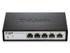
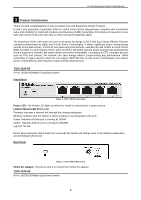
link. Reset: By pressing the Reset button for 5 seconds the Switch will change back to the default configuration and all changes will be lost. Rear Panel Figure 2- DGS-1100-05 Rear Panel 5V/1A AC adapter: The port is where to connect the 5V/1A AC adapter. DGS-1100-08 8-Port 10/100/1000Mpbs EasySmart - D-Link DGS-1100-05 | Manual - Page 7
the Reset button for 5 seconds the Switch will change back to the default configuration and all changes will be lost. Rear Panel Figure 4 - DGS-1100-08 Rear Panel 5V/1A AC adapter: The port is where to connect the 5V/1A AC adapter. DGS-1100-08P 8-Port 10/100/1000Mpbs PoE EasySmart Switch Front - D-Link DGS-1100-05 | Manual - Page 8
Reset button for 5 seconds the Switch will change back to the default configuration and all changes will be lost. Rear Panel Figure 6 - DGS-1100-08P Rear Panel 48V/1.57A Desktop adapter: The port is where to connect the 48V/1.57A Desktop adapter. DGS-1100-16 16-Port 10/100/1000Mpbs EasySmart Switch - D-Link DGS-1100-05 | Manual - Page 9
Rear Panel D-Link EasySmart Switch User Manual Figure 8- DGS-1100-16 Rear Panel Power: The power port is where to connect the AC power cord. DGS-1100-24 24-Port 10/100/1000Mpbs EasySmart Switch Front Panel Figure 9 - DGS-1100-24 Front Panel Power LED: The Power LED lights up when the Switch is - D-Link DGS-1100-05 | Manual - Page 10
of DGS-1100-08P One D-Link EasySmart Switch One Desktop Power Adapter One AC power cord Four rubber feet One ground screw that screw on the D-Link EasySmart Switch One Multi-lingual Getting Started Guide One CD with User Manual and SmartConsole Utility program Packing contents of DGS-1100-16/24 One - D-Link DGS-1100-05 | Manual - Page 11
D-Link EasySmart Switch User Manual Figure 11 - Attach the adhesive rubber pads to the bottom Rack Installation The switch can be mounted in an EIA standard size 11-inch rack, which can be placed in a wiring closet with other equipment. To install, attach the mounting brackets to the switch's side - D-Link DGS-1100-05 | Manual - Page 12
D-Link EasySmart Switch User Manual B) Reduced Air Flow - Installation of the equipment in a Step 2: Drive the T3 x 15L screws into the nylon screw anchors. Step 3: Hook the mounting holes of the switch back on the screws. Mounting on a wood wall Step 1: Drive the T3 x 15L screws into a wood wall. - D-Link DGS-1100-05 | Manual - Page 13
D-Link EasySmart Switch User Manual Figure 15 -Plugging the switch into an outlet Power Failure As a precaution, the switch should be unplugged in case of power failure. When power is resumed, plug the switch back in. Grounding the Switch This section describes how to connect the EasySmart Switch to - D-Link DGS-1100-05 | Manual - Page 14
the IP address of your PC and it is easier to initialize multiple EasySmart Switches. Please refer to the following installation instructions for the Web-based Management and the SmartConsole Utility. Using Web-based Management After a successful physical installation, you can configure the Switch - D-Link DGS-1100-05 | Manual - Page 15
D-Link EasySmart Switch User Manual Figure 17 -Connected Ethernet cable Login Web-based Management In order to login and configure the switch via an Ethernet connection, the PC must have an IP address in the same subnet as the switch. For example, if the switch has an IP address of 10.90.90.90, the - D-Link DGS-1100-05 | Manual - Page 16
D-Link EasySmart Switch User Manual NOTE: Please be sure to uninstall any existing Follow the on-screen instructions to install the utility. 5. Upon completion, go to Start > Programs > D-Link SmartConsole Utility and open the SmartConsole Utility. 6. Connect the Smart Switch to the same L2 - D-Link DGS-1100-05 | Manual - Page 17
D-Link EasySmart Switch User Manual 4 SmartConsole Utility The D-Link SmartConsole Utility allows the administrator to quickly discover all D-Link Smart Switches and EasySmart Switches which are in the same domain of the PC, collect traps and log messages, and quick access to basic configurations of - D-Link DGS-1100-05 | Manual - Page 18
D-Link EasySmart Switch User Manual NOTE: If the Group Interval is set to 0, IGMP Snooping must be disabled in the Switch or the switches will and the device. Date/Time indicates when the trap message was received, IP denotes where it comes from and Status shows the content of this trap message - D-Link DGS-1100-05 | Manual - Page 19
Monitor List By clicking on this icon you will see below options: D-Link EasySmart Switch User Manual Figure 24- SmartConsole Monitor List Monitor Save: Records the setting of the Device List as default for the next time the SmartConsole Utility is used. Monitor Save As: Records the setting of the - D-Link DGS-1100-05 | Manual - Page 20
D-Link EasySmart Switch User Manual To apply the configuration, insert the correct device password in the Confirm Password box and then click OK Figure 26 - SmartConsole Device Settings NOTE: The EasySmart Switch automatically sends out discovery packets to maintain the connection between the - D-Link DGS-1100-05 | Manual - Page 21
D-Link EasySmart Switch User Manual Figure 28 -Firmware Upgrade DHCP Refresh: If a DHCP-client enabled switch in the Device List shows the default IP is still used, it means the device did not receive an IP address from the DHCP server successfully. Select that switch and click the DHCP refresh icon - D-Link DGS-1100-05 | Manual - Page 22
: Displays the current Firmware version of this device. System Name: Displays the appointed device system name. Location: Displays where the appointed device location. SNMP: Displays the SNMP status of the device. This is not available for EasySmart switches. Trap IP: Displays the IP address of host - D-Link DGS-1100-05 | Manual - Page 23
EasySmart Switch User Manual 5 Configuration The features and functions of the D-Link EasySmart Switch can be configured for optimum use through the Web-based Management Utility. Web-based Management After a successful login you will see the screen below: Tool bar Function Tree Main Configuration - D-Link DGS-1100-05 | Manual - Page 24
. Figure 37- Tool Menu > Reboot Device Reset System Provide a safe reset option for the Switch. All configuration settings in non-volatile RAM will be reset to factory default and then the Switch will reboot. Figure 78- Tool Menu > Reset System Firmware Backup & Upgrade Click Backup to save the - D-Link DGS-1100-05 | Manual - Page 25
D-Link EasySmart Switch User Manual Click Browse to browse your inventories for a saved firmware file. Click Upgrade after selecting the firmware file you want to restore. Figure 89 - Tool Menu > Firmware backup & upgrade CAUTION: Do not disconnect the PC or remove the power cord from device until - D-Link DGS-1100-05 | Manual - Page 26
D-Link EasySmart Switch User Manual Function Tree All configuration options on the switch are accessed through the Setup menu on the left side of the screen. Click on the setup item that you want to configure. The following sections provide more detailed description of each feature and function. - D-Link DGS-1100-05 | Manual - Page 27
D-Link EasySmart Switch User Manual Figure 92- Device Information System > System Settings The System Setting allows the user to configure the IP address and the basic system information of the Switch. IP Information: There are two ways for the switch to obtain an IP address: Static and DHCP ( - D-Link DGS-1100-05 | Manual - Page 28
D-Link EasySmart Switch User Manual System > Port Settings In the Port Setting page, the status of all ports can be monitored and adjusted for optimum configuration. By selecting a range of ports (From Port and To Port), the Speed can be set for all selected ports, effective by clicking Apply. Press - D-Link DGS-1100-05 | Manual - Page 29
Frame default is disabled, Select Enabled then click Apply to turn on the jumbo frame support. Figure 147 - System > Jumbo Frame NOTE: DGS-1100-05/08/08P Supports Jumbo Frame function, but DGS-1100-16/24 will not support it. L2 Features > Port Trunking The Trunking function allows the switch to - D-Link DGS-1100-05 | Manual - Page 30
Switch User Manual Figure 158- L2 Features > Port Trunking Settings L2 Features > IGMP Snooping With Internet Group Management Protocol (IGMP) snooping, the EasySmart Switch can make intelligent multicast forwarding decisions by examining the contents of each frame's Layer 2 MAC header. By default - D-Link DGS-1100-05 | Manual - Page 31
D-Link EasySmart Switch User Manual TX (transmit) mode: Duplicates the data transmitted from the source port and forwards it to the Target Port. Click "all" to include all ports into port mirroring. RX (receive) mode: Duplicates the data that received from the source port and forwards it to the - D-Link DGS-1100-05 | Manual - Page 32
Link EasySmart Switch User Manual Figure 172- L2 Features > Statistics menu Refresh All: Renews the details collected and displayed. Clear All Counters: To reset for administrators and customer service representatives to examine of occurred in the cable. Select a port and then click the Test Now - D-Link DGS-1100-05 | Manual - Page 33
D-Link EasySmart Switch User Manual NOTE: Cable length detection is effective at every speed of 10Mbps, 100Mbps and 1Gbps. VLAN > 802.1Q VLAN A VLAN is a group of ports that can be anywhere in the network, but communicate as though they were in the same area. VLANs can be easily organized to reflect - D-Link DGS-1100-05 | Manual - Page 34
D-Link EasySmart Switch User Manual Figure 205- VLAN > 802.1Q VLAN > Add VID Figure 216- VLAN > 802.1Q VLAN > Assign PVID Rename: Click to rename the VLAN group. Delete VID: Click to delete the VLAN group. Figure 227- VLAN > 802.1Q VLAN > VLAN Table NOTE: When 802.1Q VLAN is enabled, the PortBased - D-Link DGS-1100-05 | Manual - Page 35
D-Link EasySmart Switch User Manual NOTE: When 802.1Q Management VLAN is enabled, the 802.1Q VLAN should be enabled first. VLAN > Port-Base VLAN Port-Based VLANs are the simplest and most common form of VLAN. It assigns the appliance LAN ports to VLANs, effectively transforming the appliances. You - D-Link DGS-1100-05 | Manual - Page 36
Switch User Manual 3 Video Management Software + Storage Video Management Software 2 EasySmart Switch 1 IP Cameras The Surveillance VLAN settings are accomplished in the following steps. 1. Enable Surveillance VLAN 2. Select a VLAN ID to become a surveillance VLAN and set the priority (By default - D-Link DGS-1100-05 | Manual - Page 37
unprotected ports, however, protected ports will be forbidden to forward packets to other protected ports. By default, the Traffic Segmentation is disabled. Figure 263 -VLAN >Traffic Segmentation NOTE: DGS-1100-05/08/08P Supports Traffic Segmentation function, but DGS-1100-16/24 will not support it - D-Link DGS-1100-05 | Manual - Page 38
of Quality of Service priority levels of each port, higher priority means the traffic from this port will be first handled by the switch. For packets that are untagged, the switch will assign the priority depending on your configuration. Figure 274 - QoS > 802.1p Default Priority Queuing Mechanism - D-Link DGS-1100-05 | Manual - Page 39
D-Link EasySmart Switch User Manual Click Apply for the settings to take effect. QoS > Bandwidth Control The Bandwidth Control page allows network managers to define the bandwidth settings for a specified port's transmitting and receiving data rates. Figure 296- QoS > Bandwidth Control From Port / - D-Link DGS-1100-05 | Manual - Page 40
D-Link EasySmart Switch User Manual Figure 307 - Security > Static Mac Address NOTE: DGS-1100-16/24 support 128 Static MAC Address entries, but DGS-1100-05/08/08P only support 32 entries. To initiate the removal of auto-learning for any of the uplink ports, click On to enable this feature, and then - D-Link DGS-1100-05 | Manual - Page 41
D-Link EasySmart Switch User Manual Figure 318 - Security >Dynamic Forwarding Table PoE > PoE Global Settings (DGS-1100-08P only) This page allows user to configure the global PoE settings of the device and also displays current PoE status including Total PoE Power Budget, Power Used, Power Left and - D-Link DGS-1100-05 | Manual - Page 42
D-Link EasySmart Switch User Manual • The ratio of system power supply (The percentage of PoE power supplied): Displays the percentage of PoE power supplied. PoE > PoE Port Settings (DGS-1100-08P only) DGS-1100-08P supports Power over Ethernet (PoE) as defined by the IEEE specification. It - D-Link DGS-1100-05 | Manual - Page 43
D-Link EasySmart Switch User Manual Click Apply to make the configurations take effects or click Refresh to redisplay the table. NOTE: For the PoE Port Settings table, if the classification was shown as "Legacy PD", it will be classified to non-AF PD or Legacy PD. 39 - D-Link DGS-1100-05 | Manual - Page 44
D-Link EasySmart Switch User Manual Appendix A - Ethernet Technology This chapter will describe the features of the D-Link EasySmart Switch and provide some background information about Ethernet/Fast Ethernet/Gigabit Ethernet switching technology. Gigabit Ethernet Technology Gigabit Ethernet is an - D-Link DGS-1100-05 | Manual - Page 45
D-Link EasySmart Switch User Manual Appendix B - Technical Specifications Hardware Specifications Key Components / Performance Switching Capacity: - DGS-1100-05 :10Gbps - DGS-1100-08/08P: 16Gbps - DGS-1100-16: 32Gbps - DGS-1100-24: 48Gbps Max. Forwarding Rate: - DGS-1100-05: 7.4 Mbps - DGS-1100-08/ - D-Link DGS-1100-05 | Manual - Page 46
D-Link EasySmart Switch User Manual Appendix C - Rack mount Instructions Safety Instructions - Rack Mount Instructions - The following or similar rack-mount instructions are included with the installation instructions: A) Elevated Operating Ambient - If installed in a closed or multi-unit rack - D-Link DGS-1100-05 | Manual - Page 47
-
 1
1 -
 2
2 -
 3
3 -
 4
4 -
 5
5 -
 6
6 -
 7
7 -
8
-
9
-
10
-
11
-
12
-
13
-
14
-
15
-
16
-
17
-
18
-
19
-
20
-
21
-
22
-
23
-
24
-
25
-
26
-
27
-
28
-
29
-
30
-
31
-
32
-
33
-
34
-
35
-
36
-
37
-
38
-
39
-
40
-
41
-
42
-
43
-
44
-
45
-
46
-
47
 |
 |
