D-Link DGS-1100-24 Manual
D-Link DGS-1100-24 Manual
 |
View all D-Link DGS-1100-24 manuals
Add to My Manuals
Save this manual to your list of manuals |
D-Link DGS-1100-24 manual content summary:
- D-Link DGS-1100-24 | Manual - Page 1
Ver. 1.00 - D-Link DGS-1100-24 | Manual - Page 2
D-Link EasySmart Switch User Manual Table of Contents Table of Contents ...i About This Guide...1 Terms/Usage...1 Copyright and Trademarks ...1 1 Product Introduction ...2 DGS-1100-16 ...2 Front Panel ...2 Rear Panel...2 DGS-1100-24 ...2 Front Panel ...2 Rear Panel...3 2 Hardware Installation ...4 - D-Link DGS-1100-24 | Manual - Page 3
D-Link EasySmart Switch User Manual System > System Settings ...20 System > Port Settings...21 System > Trap Settings For SmartConsole 21 System > Password Access Control ...22 L2 Features > Port Trunking...22 L2 Features > IGMP Snooping...22 L2 Features > Port Mirroring ...23 L2 Features > - D-Link DGS-1100-24 | Manual - Page 4
D-Link EasySmart Switch User Manual About This Guide This guide provides instructions to install the D-Link Gigabit Ethernet EasySmart Switch DGS-1100-16/24, how to use the Web Utility, and to configure Web-based Management step-by-step. Note: The model you have purchased may appear slightly - D-Link DGS-1100-24 | Manual - Page 5
: No link. Reset: By pressing the Reset button for 5 seconds the Switch will change back to the default configuration and all changes will be lost. Rear Panel Figure 2 - DGS-1100-16 Rear Panel Power: The power port is where to connect the AC power cord. DGS-1100-24 24-Port 10/100/1000Mpbs EasySmart - D-Link DGS-1100-24 | Manual - Page 6
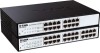
D-Link EasySmart Switch User Manual Figure 3 - DGS-1100-24 Front Panel Power LED: The Power LED lights up when the Switch is connected to a power source. Link/Act/Speed LED (Ports 1-24): Flashing: Indicates a network link through the corresponding port. Blinking: Indicates that the Switch is either - D-Link DGS-1100-24 | Manual - Page 7
damaged, please contact your local D-Link reseller for replacement. One D-Link EasySmart Switch One AC power cord Four rubber feet Screws and two mounting brackets One accessory kit for a ground screw One Multi-lingual Getting Started Guide One CD with User Manual and SmartConsole Utility program If - D-Link DGS-1100-24 | Manual - Page 8
D-Link EasySmart Switch User Manual Figure 6 - Attach the mounting brackets to the Switch Then, use the screws provided with the equipment rack to mount the switch in the rack. Figure 7 - Mount the Switch in the rack or chassis Please be aware of following safety Instructions when installing: A) - D-Link DGS-1100-24 | Manual - Page 9
D-Link EasySmart Switch User Manual Step 3 - Plugging in the AC Power Cord Users may now connect the AC power cord into the rear of the switch and to an electrical outlet (preferably one that is grounded and surge protected). Figure 8 -Plugging the switch into an outlet Power Failure As a precaution - D-Link DGS-1100-24 | Manual - Page 10
D-Link EasySmart Switch User Manual 3 Getting Started This chapter introduces the management interface of D-Link EasySmart Switch. Management Options The D-Link EasySmart Switch can be managed through any port on the device by using the Web-based Management or through any PC using the SmartConsole - D-Link DGS-1100-24 | Manual - Page 11
D-Link EasySmart Switch User Manual Figure 10 -Connected Ethernet cable Login Web-based Management In order to login and configure the switch via an Ethernet connection, the PC must have an IP address in the same subnet as the switch. For example, if the switch has an IP address of 10.90.90.90, the - D-Link DGS-1100-24 | Manual - Page 12
D-Link EasySmart Switch User Manual NOTE: Please be sure to uninstall any existing Follow the on-screen instructions to install the utility. 5. Upon completion, go to Start > Programs > D-Link SmartConsole Utility and open the SmartConsole Utility. 6. Connect the Smart Switch to the same L2 - D-Link DGS-1100-24 | Manual - Page 13
D-Link EasySmart Switch User Manual 4 SmartConsole Utility The D-Link SmartConsole Utility allows the administrator to quickly discover all D-Link Smart Switches and EasySmart Switches which are in the same domain of the PC, collect traps and log messages, and quick access to basic configurations of - D-Link DGS-1100-24 | Manual - Page 14
Link EasySmart Switch User Manual NOTE: If the Group Interval is set to 0, IGMP Snooping must be disabled in the Switch or the switches indicates when the trap message was received, IP denotes where it comes from and Status shows entries. Click OK to exit Figure 16 - SmartConsole Trap The trap icon in - D-Link DGS-1100-24 | Manual - Page 15
Link EasySmart Switch User Manual Figure 17 - SmartConsole File Monitor Save: Records the setting of the Device List as default 18 - SmartConsole Help Device Configuration The Device Configuration in the SmartConsole Utility has five icons: Device Settings Device Password Manager Multi Firmware - D-Link DGS-1100-24 | Manual - Page 16
D-Link EasySmart Switch User Manual Figure 19 - SmartConsole Device Settings NOTE: The EasySmart Switch automatically sends out discovery packets to maintain the connection between the devices and SmartConsole Utility. Therefore, ensure to configure the Group Interval setting. Device Password - D-Link DGS-1100-24 | Manual - Page 17
D-Link EasySmart Switch User Manual Figure 21 - Multi Firmware Upgrade DHCP Refresh: If a DHCP-client enabled switch in the Device List shows the default IP is still used, it means the device did not receive an IP address from the DHCP server successfully. Select that switch and click the DHCP - D-Link DGS-1100-24 | Manual - Page 18
is not available for EasySmart switches. Firmware version: Displays the current Firmware version of this device. LLDP: Displays the LLDP (Link Layer Discovery Protocol) status of the device. This feature is available only for PoE models of Web Smart switches. SNMP: Displays the SNMP status of the - D-Link DGS-1100-24 | Manual - Page 19
EasySmart Switch User Manual 5 Configuration The features and functions of the D-Link EasySmart Switch can be configured for optimum use through the Web-based Management Utility. Web-based Management After a successful login you will see the screen below: Tool bar Function Tree Main Configuration - D-Link DGS-1100-24 | Manual - Page 20
. Figure 30 - Tool Menu > Reboot Device Reset System Provide a safe reset option for the Switch. All configuration settings in non-volatile RAM will be reset to factory default and then the Switch will reboot. Figure 31 - Tool Menu > Reset System Firmware Backup & Upgrade Click Backup to save the - D-Link DGS-1100-24 | Manual - Page 21
D-Link EasySmart Switch User Manual Figure 32 - Tool Menu > Firmware backup & upgrade CAUTION: Do not disconnect the PC or remove the power cord from device until upgrade is complete. The Switch may crash if the Firmware Upgrade is incomplete. Configuration Backup & Restore Allow the current - D-Link DGS-1100-24 | Manual - Page 22
D-Link EasySmart Switch User Manual Function Tree All configuration options on the switch are accessed through the Setup menu on the left side of the screen. Click on the setup item that you want to configure. The following sections provide more detailed description of each feature and function. - D-Link DGS-1100-24 | Manual - Page 23
D-Link EasySmart Switch User Manual Figure 35 - Device Information System > System Settings The System Setting allows the user to configure the IP address and the basic system information of the Switch. IP Information: There are two ways for the switch to obtain an IP address: Static and DHCP ( - D-Link DGS-1100-24 | Manual - Page 24
D-Link EasySmart Switch User Manual System > Port Settings In the Port Setting page, the status of all ports can be monitored and adjusted for optimum configuration. By selecting a range of ports (From Port and To Port), the Speed can be set for all selected ports, effective by clicking Apply. Press - D-Link DGS-1100-24 | Manual - Page 25
the IP of the source PC Twisted pair Port Link Up/Link Down: Copper port connection information Firmware Upgrade State: Information of firmware upgrade - success or failure System > Password Access Control Setting a password is a critical tool for managers to secure the EasySmart Switch. After - D-Link DGS-1100-24 | Manual - Page 26
D-Link EasySmart Switch User Manual Figure 41 - L2 Feautres > IGMP Snooping setting L2 Features > Port Mirroring Port Mirroring is a method of monitoring network traffic that forwards a copy of each incoming and/or outgoing packet from one port of the Switch to another port where the packet can be - D-Link DGS-1100-24 | Manual - Page 27
D-Link EasySmart Switch User Manual Figure 43 - L2 Features > Loopback Detection Loopback Detection State: Use the drop-down menu to enable or disable loopback detection. The default is Disabled. Interval (1-32767): Set a Loop detection Interval between 1 and 32767 seconds. The default is 1 seconds. - D-Link DGS-1100-24 | Manual - Page 28
Management Software 2 EasySmart Switch 1 IP Cameras The Auto Surveillance VLAN settings are accomplished in the following steps. 1. Enable Auto Surveillance VLAN 2. Select a VLAN ID to become a surveillance VLAN and set the priority (By default, the priority is highest) 3. D-Link Cameras can be - D-Link DGS-1100-24 | Manual - Page 29
D-Link EasySmart Switch User Manual Figure 45 - L2 Features > Auto Surveillance VLAN Settings Figure 46 - L2 Features > Auto Surveillance VLAN Settings > Component type Cable Diagnostics The Cable Diagnostics is designed primarily for administrators and customer service representatives to examine of - D-Link DGS-1100-24 | Manual - Page 30
D-Link EasySmart Switch User Manual ‧Test Failed means some other errors occurred during cable diagnostics. Please select the same port and test again. Cable Fault Distance (meters): Indicates the distance of the cable fault from the Switch port, if the cable is less than 2 meters, it will show "No - D-Link DGS-1100-24 | Manual - Page 31
D-Link EasySmart Switch User Manual Figure 49 - VLAN > 802.1Q VLAN > Add VID Figure 50 - VLAN > 802.1Q VLAN > Assign PVID Rename: Click to rename the VLAN group. Delete VID: Click to delete the VLAN group. Figure 51 - VLAN > 802.1Q VLAN > VLAN Table NOTE: When 802.1Q VLAN is enabled, the Port28 - D-Link DGS-1100-24 | Manual - Page 32
D-Link EasySmart Switch User Manual Based VLAN settings will be set to Disabled. VLAN > Port-Base VLAN Port-Based VLANs are the simplest and most common form of VLAN. It assigns the appliance LAN ports to VLANs, effectively transforming the appliances. You can assign multiple ports to the same VLAN, - D-Link DGS-1100-24 | Manual - Page 33
D-Link EasySmart Switch User Manual Figure 53 - QoS > 802.1p Default Priority Queuing Mechanism: Select Strict Priority to process the packets with the highest priority first. Select WRR (Weighted Round-Robin) to process packets according to - D-Link DGS-1100-24 | Manual - Page 34
D-Link EasySmart Switch User Manual Figure 55 - QoS > Bandwidth Control From Port / To Port: A consecutive group of ports may be configured starting with the selected port. Type: This drop-down menu allows you to select between RX (receive), TX (transmit), and Both. This setting will determine - D-Link DGS-1100-24 | Manual - Page 35
D-Link EasySmart Switch User Manual Figure 56 - Security > Static Mac Address To initiate the removal of auto-learning for any of the uplink ports, click On to enable this feature, and then select the port(s) for auto learning to be disabled. The Static MAC Address Setting table displays the static - D-Link DGS-1100-24 | Manual - Page 36
D-Link EasySmart Switch User Manual Figure 57 - Security > Dynamic Forwarding Table 33 - D-Link DGS-1100-24 | Manual - Page 37
D-Link EasySmart Switch User Manual Appendix A - Ethernet Technology This chapter will describe the features of the D-Link EasySmart Switch and provide some background information about Ethernet/Fast Ethernet/Gigabit Ethernet switching technology. Gigabit Ethernet Technology Gigabit Ethernet is an - D-Link DGS-1100-24 | Manual - Page 38
D-Link EasySmart Switch User Manual Appendix B - Technical Specifications Hardware Specifications Key Components / Performance Switching Capacity: - DGS-1100-16: 32Gbps - DGS-1100-24: 48Gbps Max. Forwarding Rate: - DGS-1100-16: 23.8Mbps - DGS-1100-24: 35.7Mbps Forwarding Mode: Store and Forward - D-Link DGS-1100-24 | Manual - Page 39
D-Link EasySmart Switch User Manual Appendix C - Rack mount Instructions Safety Instructions - Rack Mount Instructions - The following or similar rack-mount instructions are included with the installation instructions: A) Elevated Operating Ambient - If installed in a closed or multi-unit rack - D-Link DGS-1100-24 | Manual - Page 40
-
 1
1 -
 2
2 -
 3
3 -
 4
4 -
 5
5 -
 6
6 -
 7
7 -
8
-
9
-
10
-
11
-
12
-
13
-
14
-
15
-
16
-
17
-
18
-
19
-
20
-
21
-
22
-
23
-
24
-
25
-
26
-
27
-
28
-
29
-
30
-
31
-
32
-
33
-
34
-
35
-
36
-
37
-
38
-
39
-
40
 |
 |

Ver. 1.00