D-Link DGS-1210-10P Product Manual
D-Link DGS-1210-10P Manual
 |
UPC - 790069329388
View all D-Link DGS-1210-10P manuals
Add to My Manuals
Save this manual to your list of manuals |
D-Link DGS-1210-10P manual content summary:
- D-Link DGS-1210-10P | Product Manual - Page 1
- D-Link DGS-1210-10P | Product Manual - Page 2
- D-Link DGS-1210-10P | Product Manual - Page 3
Table of Contents D-Link Web Smart Switch User Manual Table of Contents Table of Contents ...i About This Guide...1 Terms/Usage...1 Copyright and Trademarks ...1 Product Introduction ...2 DGS-1210-10P...3 Front Panel ...3 Rear Panel...3 Hardware Installation ...4 Step 1: Unpacking...4 Step 2: - D-Link DGS-1210-10P | Product Manual - Page 4
D-Link Web Smart Switch User Manual Configuration Backup & Restore ...22 Firmware Backup and Upload ...22 Tool Bar > Smart Wizard...23 Tool Bar > Online Help...23 Function Tree ...25 Device Information...25 System > System Settings ...26 System > Trap Settings For SmartConsole 27 System > Port - D-Link DGS-1210-10P | Product Manual - Page 5
Table of Contents D-Link Web Smart Switch User Manual Command Line Interface...59 To connect a switch via TELNET:...59 Logging on to the Command Line Interface 59 CLI Commands: ...59 Download...59 Upload ...60 Config ipif System...60 Logout...60 Ping ...61 Reboot ...61 Reset ...61 Show ipif ...61 - D-Link DGS-1210-10P | Product Manual - Page 6
- D-Link DGS-1210-10P | Product Manual - Page 7
About This Guide D-Link Web Smart Switch User Manual About This Guide This guide provides instructions to install the D-Link Gigabit Web Smart PoE Switch DGS-1210-10P, how to use the SmartConsole Utility, and to configure Web-based Management step-by-step. Note: The model you have purchased may - D-Link DGS-1210-10P | Product Manual - Page 8
via TELNET. Some basic tasks can be performed such as changing the Switch IP address, resetting the settings to factory defaults, setting the administrator password, rebooting the Switch, or upgrading the Switch firmware by using the Command Line Interface (CLI). In addition, users can utilize - D-Link DGS-1210-10P | Product Manual - Page 9
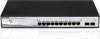
. D-Link Web Smart Switches also come with the D-View plug-in module that works with D-View 6 SNMP Management Software, and provides easy-to-use graphic interface and facilitates the operation efficiency. DGS-1210-10P 8-Port 10/100/1000Mbps plus 2 1000Base-T/SFP ports Web Smart PoE Switch Front - D-Link DGS-1210-10P | Product Manual - Page 10
Link reseller for replacement. One D-Link Web-Smart Switch One AC power cord Four rubber feet Screws and two mounting brackets One Multi-lingual Getting Started Guide One CD with User Manual to the bottom Rack Installation The switch can be mounted in an EIA standard size 19-inch rack, which can be - D-Link DGS-1210-10P | Product Manual - Page 11
2 Hardware Installation D-Link Web Smart Switch User Manual Then, use the screws provided with the equipment rack to mount the switch in the rack. Figure 5 - Mount the Switch in the rack or chassis Please be aware of following safety Instructions when installing: A) Elevated Operating Ambient - - D-Link DGS-1210-10P | Product Manual - Page 12
2 Hardware Installation D-Link Web Smart Switch User Manual Figure 6 -Plugging the switch into an outlet Power Failure As a precaution, the switch should be unplugged in case of power failure. When power is resumed, plug the switch back in. 6 - D-Link DGS-1210-10P | Product Manual - Page 13
3 Getting Started D-Link Web Smart Switch User Manual 3 Getting Started This chapter introduces the management interface of D-Link Web-Smart Switch. Management Options The D-Link Web Smart Switch can be managed through any port on the device by using the Web-based Management, or through any PC - D-Link DGS-1210-10P | Product Manual - Page 14
box appears, enter the password then click OK. The default password is admin. Figure 9 - Logon Dialog Box Smart Wizard After a successful login, the Smart Wizard will guide you through essential settings of the D-Link Web Smart Switch. Please refer to the Smart Wizard Configuration section for - D-Link DGS-1210-10P | Product Manual - Page 15
3 Getting Started D-Link Web Smart Switch User Manual Option 1: Follow these steps to install the the on-screen instructions to install the utility. 5. Upon completion, go to Start > Programs > D-Link SmartConsole Utility and open the SmartConsole Utility. 6. Connect the Smart Switch to the same - D-Link DGS-1210-10P | Product Manual - Page 16
D-Link Web Smart Switch User Manual 4 SmartConsole Utility The D-Link SmartConsole Utility allows the administrator to quickly discover all D-Link smart switches, which are in the same domain of the PC, collect traps and log messages, and quick access to basic configurations of the switch. The - D-Link DGS-1210-10P | Product Manual - Page 17
Link Web Smart Switch User Manual Web-Smart Switch will not be discovered. Log Click this icon to launch the Log window. Click View Log to show the events of the SmartConsole Utility and the device. Date/Time indicates when the message was received, IP message was received, IP denotes where it comes - D-Link DGS-1210-10P | Product Manual - Page 18
Link Web Smart Switch User Manual Figure 14 - SmartConsole File Monitor Save: Records the setting of the Device List as default for the next time the SmartConsole Utility is used. Monitor Save As: Records the setting of the Device List in an appointed filename and file path. Monitor Load: Manually - D-Link DGS-1210-10P | Product Manual - Page 19
D-Link Web Smart Switch User Manual Device Configuration The Device Configuration in the SmartConsole Utility has five icons: Device Settings Device Password Manager Multi Firmware Upgrade DHCP Refresh Web Access and the , , device buttons for the Device List. Device Settings Select a switch - D-Link DGS-1210-10P | Product Manual - Page 20
Utility D-Link Web Smart Switch User Manual Device Password Manager Select a switch from the Device List. Click on this icon to launch the Device Password Manager window. Here you can enter a new password and confirm it. Figure 17 - SmartConsole Device Password Manager Multi Firmware Upgrade - D-Link DGS-1210-10P | Product Manual - Page 21
D-Link Web Smart Switch User Manual Figure 19 - DHCP Refresh Web Access Select a switch from the Device List. Click this icon to launch your Internet browser (eg. The Internet Explorer). Here you can configure the Switch through the Web-based Management utility. You may also get into the Web - D-Link DGS-1210-10P | Product Manual - Page 22
Link Web Smart Switch User Manual disconnected. . Please check if the IP Address: Displays the current IP addresses of devices. MAC Address: firmware upgrade is required again. NOTE: The LLDP function is only provided by PoE models. For non-PoE models, the LLDP column will appear blank. 16 - D-Link DGS-1210-10P | Product Manual - Page 23
5 Configuration D-Link Web Smart Switch User Manual 5 Configuration The features and functions of the D-Link Web Smart Switch can be configured for optimum use through the Web-based Management Utility. Smart Wizard Configuration After a successful login, the Smart Wizard will guide you through - D-Link DGS-1210-10P | Product Manual - Page 24
5 Configuration D-Link Web Smart Switch User Manual SNMP Settings The SNMP Setting allows you to quickly enable/disable the SNMP function and configure the SNMP community name. For the complete SNMP function, please check "Setup Menu > System > SNMP Settings" in the Web Interface. The default SNMP - D-Link DGS-1210-10P | Product Manual - Page 25
D-Link Web Smart Switch User Manual System Settings You can manually change the system IP Address, Subnet Mask, and Gateway address by selecting Static and clicking Apply. You can further configure and read more about the above settings in the "Setup Menu > System > System Settings". The default - D-Link DGS-1210-10P | Product Manual - Page 26
5 Configuration D-Link Web Smart Switch User Manual Web-based Management After clicking the Exit button in Smart Wizard you will see the screen below: Tool Bar Function Tree Figure 27 - Web-based Management Main Configuration Screen The above image is the Web-based Management screen. The three - D-Link DGS-1210-10P | Product Manual - Page 27
Backup and Restore, Firmware Backup and Upgrade. Figure 31 - Tool Menu Reset Provide a safe reset option for the Switch. All configuration settings in non-volatile RAM will be reset to factory default except for the IP address. Figure 32 - Tool Menu > Reset Reset System Provide another safe - D-Link DGS-1210-10P | Product Manual - Page 28
Link Web Smart Switch User Manual Figure 33 - Tool Menu > Reset System Reboot Device Provide a safe way to reboot the system. Click Reboot to restart the switch to transfer files from/to a remote TFTP server. Specify TFTP Server IP Address and File Name for the configuration file you want to save to - D-Link DGS-1210-10P | Product Manual - Page 29
5 Configuration D-Link Web Smart Switch User Manual Figure 36 - Tool Menu > Firmware Backup and Upload HTTP: Backup or upgrade the firmware to or from your local PC drive. Click Backup to save the firmware to your disk. Click Browse to browse your inventories for a saved firmware file. Click - D-Link DGS-1210-10P | Product Manual - Page 30
5 Configuration D-Link Web Smart Switch User Manual Figure 38 - User Guide Micro Site 24 - D-Link DGS-1210-10P | Product Manual - Page 31
of the switch, including essential information such as firmware & hardware information, and IP address. It also offers an overall status of common software features: RSTP: Click Setting to link to Configuration > Spanning Tree > STP Global Settings. Default is disabled. Port Mirroring: Click - D-Link DGS-1210-10P | Product Manual - Page 32
5 Configuration D-Link Web Smart Switch User Manual Figure 40 - Device Information System > System Settings The System Setting allows the user to configure the IP address and the basic system information of the Switch. IP Information: There are two ways for the switch to obtain an IP address: - D-Link DGS-1210-10P | Product Manual - Page 33
D-Link Web Smart Switch User Manual System > Trap Settings For SmartConsole By configuring the Trap Setting, it allows SmartConsole Utility to monitor specified events on this Web-Smart Switch. By default, Trap Setting is disabled. When the Trap Setting is enabled, enter the Destination IP - D-Link DGS-1210-10P | Product Manual - Page 34
network. The default SNMP setting is disabled. Click Enabled to set Community Settings and then Apply. Figure 44 - System > SNMP Setting Community Setting: In support of SNMP version 1, the Web-Smart Switch accomplishes user authentication by using Community Settings that function as passwords. The - D-Link DGS-1210-10P | Product Manual - Page 35
5 Configuration D-Link Web Smart Switch User Manual The default community strings for the Switch used for SNMP v.1 management access are: Read_Only: The community with read-only privilege allows authorized management stations to retrieve MIB objects. The default name is public. Read_Write: The - D-Link DGS-1210-10P | Product Manual - Page 36
, but an operational problem has occurred. Informational Jumbo Frame D-Link Gigabit Web Smart Switches support jumbo frames (frames larger than the Ethernet frame size of 1536 bytes) of up to 10,000 bytes (tagged). Default the VID as 1, no default name, and all ports as "Untagged" Rename: Click - D-Link DGS-1210-10P | Product Manual - Page 37
5 Configuration D-Link Web Smart Switch User Manual Figure 48 - Configuration > 802.1Q VLAN > Default Setting Figure 49 - Configuration > 802.1Q VLAN is absent, or if the resource to be shared is not capable of supporting tagged VLAN (for example, a printer). The example below is a typical - D-Link DGS-1210-10P | Product Manual - Page 38
5 Configuration D-Link Web Smart Switch User Manual PCs 1, 2, and 3 cannot communicate with each other; but all of them need to access the servers or the Internet behind the firewall. PC 1 (Port 2, V2) PC 2 (Port 3, V3) PC 3 (Port 4, V4) Firewall, V1~V4 Server, V1~V4 Figure 52 - Configuration - D-Link DGS-1210-10P | Product Manual - Page 39
5 Configuration D-Link Web Smart Switch User Manual Figure 54 - Configuration > 802.1Q VLAN > Asymmetric VLAN - Create VLANs 3. Configuring the PVID of access VLAN Configure the PVID setting located at the bottom of the VLAN configuration page. The user needs to set the shared set of ports as PVID - D-Link DGS-1210-10P | Product Manual - Page 40
Link Web Smart Switch User Manual Figure 57 - Configuration > Voice VLAN > Voice VLAN Setting Voice VLAN State: Select to enable or disable Voice VLAN. The default a period of time (in hours) to remove a port from the voice VLAN if the port is an automatic VLAN member. When the last voice device - D-Link DGS-1210-10P | Product Manual - Page 41
5 Configuration D-Link Web Smart Switch User Manual There are some pre-defined OUIs and when the user configures personal OUI, these pre-defined OUIs must be avoided. Below are the pre-defined - D-Link DGS-1210-10P | Product Manual - Page 42
5 Configuration D-Link Web Smart Switch User Manual Configuration > Link Aggregation > LACP Port Settings The LACP Port Settings is used to create port trunking groups on the Switch. The user may set which ports will be active and passive in processing and sending LACP control frames Figure 60 - - D-Link DGS-1210-10P | Product Manual - Page 43
5 Configuration D-Link Web Smart Switch User Manual Figure 61 - Configuration > IGMP Snooping Configuration By default, IGMP is disabled. If enabled, the IGMP Global Settings will need to be entered: Host Timeout (130-153025 sec): This is the interval after which a learned host port entry will be - D-Link DGS-1210-10P | Product Manual - Page 44
D-Link Web Smart Switch User Manual Figure 63 - Configuration > IGMP Multicast Entry Table Configuration > Port Mirroring Port Mirroring is a method of monitoring network traffic that forwards a copy of each incoming and/or outgoing packet from one port of the Switch to another port, where - D-Link DGS-1210-10P | Product Manual - Page 45
D-Link Web Smart Switch User Manual Figure 66 - Configuration > Loopback Detection Loopback Detection State: Use the drop-down menu to enable or disable loopback detection. The default is Disabled. Interval (1-32767): Set a Loop detection Interval between 1 and 32767 seconds. The default is - D-Link DGS-1210-10P | Product Manual - Page 46
5 Configuration D-Link Web Smart Switch User Manual If choosing SNTP for the clock source, then the following parameters will be available: SNTP First Server: Specify the IP address of the primary SNTP server from which the system time is retrieved. SNTP Second Server: Specify the IP address of - D-Link DGS-1210-10P | Product Manual - Page 47
5 Configuration D-Link Web Smart Switch User Manual The IEEE 802.1w Rapid Spanning Tree Protocol (RSTP) evolved from the 802.1D STP standard. RSTP was developed in order to overcome some limitations of STP that impede the function of some recent switching innovations. The basic function and much - D-Link DGS-1210-10P | Product Manual - Page 48
5 Configuration D-Link Web Smart Switch User Manual An STP Group spanning tree works in the same way as the switch-level spanning tree, but the root bridge concept is replaced with a root port concept. A root port is a port of the group that is elected based on port priority and port cost, to be - D-Link DGS-1210-10P | Product Manual - Page 49
Link Web Smart Switch User Manual Like edge ports, P2P ports transition to a forwarding state rapidly thus benefiting from RSTP. A p2p value of false indicates that the port cannot have p2p status. Auto allows the port True, the port will never be selected to be the Root port. The default value is - D-Link DGS-1210-10P | Product Manual - Page 50
5 Configuration D-Link Web Smart Switch User Manual From Port / To Port: A consecutive group of ports may be configured starting with the selected port. Type: This drop-down menu allows you to select between RX (receive), TX (transmit), and Both. This setting will determine whether the bandwidth - D-Link DGS-1210-10P | Product Manual - Page 51
5 Configuration D-Link Web Smart Switch User Manual Figure 74 - QoS > DSCP Priority Settings Select QoS Mode: D-Link Smart Switch allows the user to prioritize the traffic based on the 802.1p priority in the VLAN tag or the DSCP (Differentiated Services Code Point) priority in the IP header. Only - D-Link DGS-1210-10P | Product Manual - Page 52
5 Configuration D-Link Web Smart Switch User Manual To define a management station IP setting, click the Add Host button and type in the IP address and Subnet mask. Click the Apply button to save your settings. You may permit only single or a range of IP addresses by different IP mask settings, - D-Link DGS-1210-10P | Product Manual - Page 53
5 Configuration D-Link Web Smart Switch User Manual software and the RADIUS server. Depending on the authenticated results, the port is either made authentication server. Default is 16 seconds. MaxReq (1 - 10): This parameter specifies the maximum number of times that the switch retransmits an EAP - D-Link DGS-1210-10P | Product Manual - Page 54
5 Configuration D-Link Web Smart Switch User Manual If Auto is selected, it will enable 802.1X and cause the port to begin in the unauthorized state, allowing only EAPOL frames to be sent and received through the port. The authentication process begins when the link state of the port transitions - D-Link DGS-1210-10P | Product Manual - Page 55
5 Configuration D-Link Web Smart Switch User Manual Monitoring > Statistics The Statistics screen displays the status of each port packet count. Figure 81 - Monitoring > Statistics Refresh All: Renews the details collected and displayed. Clear All Counters: To reset the details displayed. TxOK: - D-Link DGS-1210-10P | Product Manual - Page 56
Link Web Smart Switch User Manual Monitoring > Cable Diagnostics The Cable Diagnostics is designed primarily for administrators and customer service representatives to examine the copper cable quality. It rapidly determines the type of cable errors occurred in the cable. Select a port Gigabit ports - D-Link DGS-1210-10P | Product Manual - Page 57
5 Configuration D-Link Web Smart Switch User Manual Figure 84 - Monitoring > System Log ID: Displays an each packet's header. This criterion can be specified on a basis of the MAC address, or IP address. The ACL Configuration Wizard will aid with the creation of access profiles and ACL Rules. - D-Link DGS-1210-10P | Product Manual - Page 58
Link Web Smart Switch User Manual Service Type: Specify the type of service. The possible values are: Any - Indicates ACL action will be on packets from any service drops packets if all other ACL criteria is met. Port: Enter a range of ports to be configured. Press Apply for the settings to take - D-Link DGS-1210-10P | Product Manual - Page 59
: To delete an access profile. To manually add a profile, click Add ACL Profile: D-Link Web Smart Switch User Manual Figure 87 - Add Access Profile The if you want to check a network of 192.168.1.0/24, then you should enter the IP mask as 255.255.255.0. NOTE: You cannot select Payload in a MAC - D-Link DGS-1210-10P | Product Manual - Page 60
D-Link Web Smart Switch User Manual Profile IP. Possible values are ICMP, IGMP, TCP, and UDP. ICMP Type: Specify the ICMP packet type. ICMP Code: Specify the ICMP packet Code. IGMP Type: Specify the IGMP packet type. Source Port: Specify the TCP or UDP source port value. Destination Port - D-Link DGS-1210-10P | Product Manual - Page 61
5 Configuration D-Link Web Smart Switch User Manual NOTE: The switch begins the access rule with the 6. DGS-1210-10P works with all D-Link 802.3af or 802.3at capable devices. The Switch also works in PoE mode with all non-802.3af capable D-Link AP, IP Cam and IP phone equipment via the PoE splitter - D-Link DGS-1210-10P | Product Manual - Page 62
Link Web Smart Switch User Manual Figure 92 - PoE > PoE Port Setting State: Select "Enabled" or "Disabled" to configure PoE function for designated port(s). Default is Enabled. Time Range: Select the PoE time profile configured from Time-Based PoE > Time Range Settings to enable the time-based PoE - D-Link DGS-1210-10P | Product Manual - Page 63
5 Configuration D-Link Web Smart Switch User Manual And the Deny low priority port applied the port priority setting configured from PoE port setting page. Default setting is Deny next port. Note: The power management policy is only effective while PoE system entering guard band mode (0 < - D-Link DGS-1210-10P | Product Manual - Page 64
D-Link Web Smart Switch User Manual LLDP: When this function is Enabled, the switch can start to transmit, receive and process the LLDP packets. For the advertisement of LLDP packets, the switch announces the information to its neighbor through ports. For the receiving of LLDP packets, the switch - D-Link DGS-1210-10P | Product Manual - Page 65
6 Command Line Interface D-Link Web Smart Switch User Manual 6 Command Line Interface The D-Link Web Smart Switch allows a computer or terminal to perform some basic monitoring and configuration tasks by using the Command Line Interface (CLI) via TELNET protocol. To connect a switch via TELNET: 1. - D-Link DGS-1210-10P | Product Manual - Page 66
D-Link Web Smart Switch User Manual firmware_fromTFTP cfg_fromTFTP tftp://ip-address/ filename Download and install new firmware on the Switch from a TFTP server. Download a switch configuration file from a TFTP server. The IP address of the TFTP server. The filename of the firmware or switch - D-Link DGS-1210-10P | Product Manual - Page 67
Web Smart Switch User Manual NOTE: Save your configuration changes before logging out. Ping This command checks if another computer is on the network and listens for connections. You can ping the switch from any IP workstation the switch is connected to through the managed VLAN (VLAN 1 by default - D-Link DGS-1210-10P | Product Manual - Page 68
Command Line Interface D-Link Web Smart Switch User Manual Figure 101 - The show switch Command Config account admin password The command sets the administrator password. Syntax config account admin password Parameter Parameter Description The new password of the administrator - D-Link DGS-1210-10P | Product Manual - Page 69
D-Link Web Smart Switch User Manual Appendix A - Ethernet Technology This chapter will describe the features of the D-Link Web Smart Switch and provide some background information about Ethernet/Fast Ethernet/Gigabit Ethernet switching technology. Gigabit Ethernet Technology Gigabit Ethernet - D-Link DGS-1210-10P | Product Manual - Page 70
D-Link Web Smart Switch User Manual Appendix B - Technical Specifications Hardware Specifications Key Components / Performance Switching Capacity: - DGS-1210-10P: 20Gbps Max. Forwarding Rate - DGS-1210-10P: 14.88Mpps Forwarding Mode: Store and Forward Packet Buffer memory: - DGS-1210-10P - D-Link DGS-1210-10P | Product Manual - Page 71
On/Off events, PoE Power Error events and PoE over max power budget events Port access control Web-based configuration backup / restoration Web-based firmware backup/restore Firmware upgrade using SmartConsole Utility & Web-based management Reset, Reboot D-Link Web Smart Switch User Manual 63 - D-Link DGS-1210-10P | Product Manual - Page 72
Appendix C - Rack mount Instructions D-Link Web Smart Switch User Manual Appendix C - Rack mount Instructions Safety Instructions - Rack Mount Instructions - The following or similar rack-mount instructions are included with the installation instructions: A) Elevated Operating Ambient - If - D-Link DGS-1210-10P | Product Manual - Page 73
-
 1
1 -
 2
2 -
 3
3 -
 4
4 -
 5
5 -
 6
6 -
 7
7 -
8
-
9
-
10
-
11
-
12
-
13
-
14
-
15
-
16
-
17
-
18
-
19
-
20
-
21
-
22
-
23
-
24
-
25
-
26
-
27
-
28
-
29
-
30
-
31
-
32
-
33
-
34
-
35
-
36
-
37
-
38
-
39
-
40
-
41
-
42
-
43
-
44
-
45
-
46
-
47
-
48
-
49
-
50
-
51
-
52
-
53
-
54
-
55
-
56
-
57
-
58
-
59
-
60
-
61
-
62
-
63
-
64
-
65
-
66
-
67
-
68
-
69
-
70
-
71
-
72
-
73
 |
 |
