D-Link DGS-3630 Quick Install Guide
D-Link DGS-3630 Manual
 |
View all D-Link DGS-3630 manuals
Add to My Manuals
Save this manual to your list of manuals |
D-Link DGS-3630 manual content summary:
- D-Link DGS-3630 | Quick Install Guide - Page 1
- D-Link DGS-3630 | Quick Install Guide - Page 2
DGS-3630 Series Layer 3 Stackable Managed Switch Hardware Installation Guide Information in this document is subject to change without notice. Reproduction in any manner whatsoever, without the written permission of D-Link Corporation, is strictly forbidden. Trademarks used in this text: D-Link and - D-Link DGS-3630 | Quick Install Guide - Page 3
DGS-3630 Series Layer 3 Stackable Managed Switch Hardware Installation Guide contains detailed information about the hardware specifications of the switches in this series. It also contains brief information on how to configure and manage a switch in this series. This manual Instructions service - D-Link DGS-3630 | Quick Install Guide - Page 4
DGS-3630 Series Layer 3 Stackable Managed Switch Hardware Installation Guide The product does not operate correctly when the operating instructions the system gets wet contact your trained service provider. Do not push any Instructions. ATTENTION: Risque d'explosion si la batterie est remplacée - D-Link DGS-3630 | Quick Install Guide - Page 5
DGS-3630 Series Layer 3 Stackable Managed Switch Hardware Installation Guide General Precautions for Rack-Mountable components in the rack. Do not step on or stand on any component when servicing other components in a rack. CAUTION: Never defeat the ground conductor or operate the equipment - D-Link DGS-3630 | Quick Install Guide - Page 6
...12 DGS-3630-28TC Switch ...12 Front Panel Components...12 LED Indicators ...13 Rear Panel Components ...14 Side Panel Components ...14 DGS-3630-28SC Switch ...15 Front Panel Components...15 LED Indicators ...16 Rear Panel Components ...17 Side Panel Components ...17 DGS-3630-28PC Switch - D-Link DGS-3630 | Quick Install Guide - Page 7
DGS-3630 Series Layer 3 Stackable Managed Switch Hardware Installation Guide DPS-700 ...34 DPS-800 ...36 Console Port ...43 Connecting to the RJ45 Console Port ...43 Connecting to the Mini-USB Console Port ...45 Connecting to the Switch for the First Time...47 Creating a User Account...47 Configuring - D-Link DGS-3630 | Quick Install Guide - Page 8
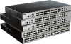
may span great distances. The D-Link DGS-3630 Series includes the following switches: DGS-3630-28TC supports twenty RJ45 ports (10/100/1000 Mbps), four Combo RJ45/SFP ports (10/100/1000 Mbps and 100/1000 Mbps), and four SFP+ ports (10G). DGS-3630-28SC supports twenty SFP ports (100/1000 Mbps - D-Link DGS-3630 | Quick Install Guide - Page 9
DGS-3630 Series Layer 3 Stackable Managed Switch Hardware Installation Guide One CD containing the Web UI Reference Guide, CLI Reference Guide, D-View module, and additional software. If any item is missing or damaged, please contact your local D-Link MPLS OAM Class of Service (CoS) Two-rate Three - D-Link DGS-3630 | Quick Install Guide - Page 10
DGS-3630 Series Layer 3 Stackable Managed Switch Hardware Installation Guide NAP Support (IPv4/IPv6) Trusted Host activated via ACL Cable Diagnostics 802.3ah Ethernet Link D-Link Discover Protocol (DDP), and D-Link Network Assistant (DNA) DHCP Server and Client, and DHCP Auto- configuration - D-Link DGS-3630 | Quick Install Guide - Page 11
DGS-3630 Series Layer 3 Stackable Managed Switch Hardware Installation Guide Client MIB, RADIUS Accounting Client MIB, Ping & TRACEROUTE MIB, IPv6 MIB, ICMPv6 MIB, Entity MIB, VRRP MIB, RIPv2 MIB, OSPF MIB, IPv4 Multicast Routing MIB, - D-Link DGS-3630 | Quick Install Guide - Page 12
Managed Switch Hardware Installation Guide 2. Hardware Components This chapter describes the front, rear, and side panel components of all switches in the series. DGS-3630-28TC Switch DGS-3630-28SC Switch DGS-3630-28PC Switch DGS-3630-52TC Switch DGS-3630-52PC Switch DGS-3630-28TC Switch Front Panel - D-Link DGS-3630 | Quick Install Guide - Page 13
Guide LED Indicators Located on the front panel of this switch are LED indicators: Power, Console, RPS, Fan Err, USB, MGMT, Link/Act indicators for all the ports, and Stack ID. LED Power Console RPS Fan Err USB MGMT Link/Act LEDs Stack ID . Figure 2-2 LED indicators for the DGS-3630-28TC - D-Link DGS-3630 | Quick Install Guide - Page 14
LED DGS-3630 Series Layer 3 Stackable Managed Switch Hardware Installation Guide Description The letter 'H' will be an outlet for an external redundant power supply. Figure 2-3 Rear panel view of the DGS-3630-28TC Components that can be found on the rear panel of this switch are listed in - D-Link DGS-3630 | Quick Install Guide - Page 15
3 Stackable Managed Switch Hardware Installation Guide Figure 2-4 Side panels of the DGS-3630-28TC DGS-3630-28SC Switch Front Panel Components The front panel of DGS-3630-28SC features a variety of LED indicators and ports. Figure 2-5 Front panel view of the DGS-3630-28SC Ports that can be found - D-Link DGS-3630 | Quick Install Guide - Page 16
Guide LED Indicators Located on the front panel of this switch are LED indicators: Power, Console, RPS, Fan Err, USB, MGMT, Link/Act indicators for all the ports, and Stack ID. LED Power Console RPS Fan Err USB MGMT Link/Act LEDs Stack ID Figure 2-6 LED indicators for the DGS-3630-28SC - D-Link DGS-3630 | Quick Install Guide - Page 17
LED DGS-3630 Series Layer 3 Stackable Managed Switch Hardware Installation Guide Description automatically by the system. The outlet for an external redundant power supply. Figure 2-7 Rear Panel view of the DGS-3630-28SC Components that can be found on the rear panel of this switch are listed in - D-Link DGS-3630 | Quick Install Guide - Page 18
Managed Switch Hardware Installation Guide Figure 2-8 Side panels of the DGS-3630-28SC DGS-3630-28PC Switch Front Panel Components The front panel of DGS-3630-28PC features a variety of LED indicators, ports and a Mode button. Figure 2-9 Front panel view of the DGS-3630-28PC Ports that can be - D-Link DGS-3630 | Quick Install Guide - Page 19
DGS-3630 Series Layer 3 Stackable Managed Switch Hardware Installation Guide Console RPS Fan Err USB MGMT Link/Act LEDs PoE Figure 2-10 LED indicators for the DGS-3630-28PC link present or when this interface was shut down from within the Switch's configuration. The Switch has LED indicators for Link - D-Link DGS-3630 | Quick Install Guide - Page 20
DGS-3630 Series Layer 3 Stackable Managed Switch Hardware Installation Guide h, E, and G. The stacking ID (1 to 9) can be assigned manually by the user or automatically by the system. The letter 'H' will . Figure 2-11 Rear panel view of the DGS-3630-28PC Components that can be found on the rear - D-Link DGS-3630 | Quick Install Guide - Page 21
Stackable Managed Switch Hardware Installation Guide Figure 2-12 Side panels of the DGS-3630-28PC DGS-3630-52TC Switch Front Panel Components The front panel of DGS-3630-52TC features a variety of LED indicators and ports. Figure 2-13 Front panel view of the DGS-3630-52TC Ports that can be found - D-Link DGS-3630 | Quick Install Guide - Page 22
DGS-3630 Series Layer 3 Stackable Managed Switch Hardware Installation Guide LED Power Console RPS Fan Err Link manually console ports, an alarm port, an AC power connector, a power cord retainer hole, and an outlet for an external redundant power supply. Figure 2-15 Rear panel view DGS-3630-52TC - D-Link DGS-3630 | Quick Install Guide - Page 23
DGS-3630 Series Layer 3 Stackable Managed Switch Hardware Installation Guide The Mini-USB console port can be used to connect to the CLI of the Switch for configuration, management, and detected. This LED will light solid green after a link to the MGMT port was successfully established. This LED - D-Link DGS-3630 | Quick Install Guide - Page 24
DGS-3630 Series Layer 3 Stackable Managed Switch Hardware Installation Guide DGS-3630-52TC DGS-3630-52PC Switch Front Panel Components The front panel of DGS-3630-52PC and 1 Gbps wirespeeds and support a wide collection of SFP Console, RPS, Fan Err, Link/Act and PoE indicators for all the ports, Link - D-Link DGS-3630 | Quick Install Guide - Page 25
Switch Hardware Installation Guide Figure 2-18 LED indicators for the DGS-3630-52PC LED Power Console RPS Fan Err Link/Act LEDs PoE following letters H, h, E, and G. The stacking ID (1 to 9) can be assigned manually by the user or automatically by the system. The letter 'H' will be displayed if - D-Link DGS-3630 | Quick Install Guide - Page 26
, an MGMT port, two console ports, an alarm port, a security lock, and a GND. Figure 2-19 Rear panel view DGS-3630-52PC Components that can be found Type-A port provides an additional storage space for portable firmware images and configuration files that can be copied to and from the NVRAM of the - D-Link DGS-3630 | Quick Install Guide - Page 27
DGS-3630 Series Layer 3 Stackable Managed Switch Hardware Installation Guide Description This LED will blink when activity on this port is taking place. This LED will be off when there is no link present or when this interface was shut down from within the Switch's configuration the DGS-3630-52PC 27 - D-Link DGS-3630 | Quick Install Guide - Page 28
DGS-3630 Series Layer 3 Stackable Managed Switch Hardware Installation Guide 3. Installation Installation Guidelines Installing to the Switch Install the Switch on a sturdy, level surface that can support the weight of the Switch (see the Weight section in Appendix A - the Switch for ventilation. 28 - D-Link DGS-3630 | Quick Install Guide - Page 29
DGS-3630 Series Layer 3 Stackable Managed Switch Hardware Installation Guide Installing the Switch in a Standard 19" Rack This section is used to guide connect various other networking devices to this switch that do not support the standard RJ45 wiring connection. These ports are generally used to - D-Link DGS-3630 | Quick Install Guide - Page 30
DGS-3630 Series Layer 3 Stackable Managed Switch Hardware Installation Guide used to connect devices to the Switch SFP+ ports. Figure 3-4 Inserting transceivers into the transceiver ports The SFP+ ports also support other transceiver form factors like SFP and SFP+ transceivers. A complete list of SFP - D-Link DGS-3630 | Quick Install Guide - Page 31
DGS-3630 Series Layer 3 Stackable Managed Switch Hardware Installation Guide Power Failure (AC Power) In the event install the power cord retainer together with the power cord. NOTE: The DGS-3630-28PC and DGS-3630-52PC do not support the installation of the power cord retainer. 1. With the rough side - D-Link DGS-3630 | Quick Install Guide - Page 32
DGS-3630 Series Layer 3 Stackable Managed Switch Hardware Installation Guide Figure 3-7 Slide the Retainer through the Tie Wrap 4. Circle the tie of the retainer around the power cord and into the locker of the retainer. Figure 3-8 Circle around the power cord 32 - D-Link DGS-3630 | Quick Install Guide - Page 33
DGS-3630 Series Layer 3 Stackable Managed Switch Hardware Installation Guide 5. Fasten the tie of the retainer until the power cord is secured. Figure 3-9 Secure the power cord Installing the Redundant Power Supply (RPS) The Redundant - D-Link DGS-3630 | Quick Install Guide - Page 34
voltage requirements of the switches being supported. The DPS-500 can both be installed into a DPS-800 rack mount unit. The DPS-500 can only be used with the DGS-3630-28TC, DGS-3630-28SC, and DGS-3630-52TC. The DPS-700 can only be used with the DGS-3630-28PC and DGS-3630-52PC. DPS-700 The DPS-700 is - D-Link DGS-3630 | Quick Install Guide - Page 35
DGS-3630 Series Layer 3 Stackable Managed Switch Hardware Installation Guide Figure 3-11 Front view of the supply is now in operation. 4. No configuration in the Switch's firmware is needed for this installation. NOTE: See the RPS Quick Installation Guide for more information. Figure 3-12 Rear view - D-Link DGS-3630 | Quick Install Guide - Page 36
Managed Switch Hardware Installation Guide CAUTION: Do not connect the DPS-700 to the DGS-3630-28PC/52PC by using the 14- mountable unit designed to hold up to two RPS units. NOTE: This rack-mount chassis supports the following RPS units: DPS-500A and DPS-500DC. The following diagram illustrates how - D-Link DGS-3630 | Quick Install Guide - Page 37
DGS-3630 Series Layer 3 Stackable Managed Switch Hardware Installation Guide Figure 3-14 Install the DPS-800 in an Equipment Rack 37 - D-Link DGS-3630 | Quick Install Guide - Page 38
DGS-3630 Series Layer 3 Stackable Managed Switch Hardware Installation Guide 4. Switch Connections Switch to an End port to the Switch via a twisted pair Category 5e UTP/STP cable. Connect a switch supporting an optical fiber uplink to the Switch's SFP/SFP+ ports via fiber optical cabling. Figure - D-Link DGS-3630 | Quick Install Guide - Page 39
Installation Guide Switch Stacking The DGS-3630 series supports stacking up to 9 switches together while being managed through one console overall reliability, serviceability, and availability. Duplex Chain - The Duplex Chain topology stacks switches together in a chain-link format. Using - D-Link DGS-3630 | Quick Install Guide - Page 40
DGS-3630 Series Layer 3 Stackable Managed Switch Hardware Installation Guide The figure below illustrates how switches can be stacked in a Duplex Chain formation using optical fiber cables connected to SFP+ transceivers or DAC with SFP+ connectors where the 2-port stacking configuration is used. - D-Link DGS-3630 | Quick Install Guide - Page 41
DGS-3630 Series Layer 3 Stackable Managed Switch Hardware Installation Guide The figure below illustrates how switches can be stacked in a Duplex Ring formation using optical fiber cables connected to SFP+ transceivers or DAC with SFP+ connectors where the 2-port stacking configuration is used. - D-Link DGS-3630 | Quick Install Guide - Page 42
DGS-3630 Series Layer 3 Stackable Managed Switch Hardware Installation Guide Switch to a Server The Switch is ideal for connecting to a network backbone, server, or server farm. The RJ45 ports operate at a speed of 10/100/ - D-Link DGS-3630 | Quick Install Guide - Page 43
information about the Web UI, refer to the DGS-3630 Series Web UI Reference Guide. Connecting to the Console Port The front panel of the Switch provides an RJ45 and a mini-USB console port to connect a remote system for monitoring and configuring the Switch. Both ports require their respective - D-Link DGS-3630 | Quick Install Guide - Page 44
DGS-3630 Series Layer 3 Stackable Managed Switch Hardware Installation Guide Connect the male DB9 connector on the console cable (shipped with the Switch) to the RS-232 serial port on the computer running terminal emulation software then insert the RJ45 connector into the RJ45 console configuring - D-Link DGS-3630 | Quick Install Guide - Page 45
DGS-3630 Series Layer 3 Stackable Managed Switch Hardware Installation Guide Connecting to the Mini-USB Console Port To use the mini-USB console port, the following equipment is needed: A terminal or a computer with a USB 2.0 port and the ability to emulate a terminal. A console cable with a 5- - D-Link DGS-3630 | Quick Install Guide - Page 46
DGS-3630 Series Layer 3 Stackable Managed Switch Hardware Installation Guide Set the terminal emulation software as init Starting runtime image Device Discovery Configuration init 100 % 100 % 100 % 100 % After the boot sequence has been completed, the console login screen will be displayed. 46 - D-Link DGS-3630 | Quick Install Guide - Page 47
the Switch or changing its configuration. This section will explain how to log into the Switch's Command Line Interface via the out-of-band console connection. Upon initial connection to the Switch, the login screen appears (see example below). DGS-3630-28PC Gigabit Ethernet Switch Switch - D-Link DGS-3630 | Quick Install Guide - Page 48
DGS-3630 Series Layer 3 Stackable Managed Switch Hardware Installation Guide 3. Enter configure this user account to have Administrative (15) privileges. 5. Enter the line console command to enter the Line Configuration Mode Link status is up IP address is 192.168.0.1/24 Gateway is 0.0.0.0 Switch# - D-Link DGS-3630 | Quick Install Guide - Page 49
DGS-3630 Series Layer 3 Stackable Managed Switch Hardware Installation Guide The IP settings or enabled status of the MGMT port can be changed through the console port. For example, to change the IP address of the MGMT port, use the following commands: Switch#configure terminal Switch(config)# - D-Link DGS-3630 | Quick Install Guide - Page 50
DGS-3630 Series Layer 3 Stackable Managed Switch Hardware Installation Guide Management Information Base (MIB) A Management management software. In addition to the standard MIB-II, the Switch also supports its own proprietary enterprise MIB as an extended Management Information Base. The proprietary - D-Link DGS-3630 | Quick Install Guide - Page 51
DGS-3630 Series Layer 3 Stackable Managed Switch Hardware Installation Guide 6. Web-based Switch Configuration Introduction Logging into the Web UI Web User Interface (Web UI) Introduction Most software functions of the Switch can be managed, configured browsers are supported: RJ45 console port, - D-Link DGS-3630 | Quick Install Guide - Page 52
DGS-3630 Series Layer 3 Stackable Managed Switch Hardware Installation Guide NOTE: After a user account was created, port monitoring, are accessible from here. Click the D-Link logo to go to the D-Link website. This area displays a file explorer-type menu tree with all configurable options. 52 - D-Link DGS-3630 | Quick Install Guide - Page 53
AREA 3 AREA 4 DGS-3630 Series Layer 3 Stackable Managed Switch Hardware Installation Guide Select the folder or window to display can be viewed and configured in this folder. Features regarding the Quality of Service functionality of the Switch can be viewed and configured in this folder. Features - D-Link DGS-3630 | Quick Install Guide - Page 54
DGS-3630 Series Layer 3 Stackable Managed Switch Hardware Installation Guide Appendix A - Technical DGS-3630-28TC: Supports DPS-500 and DPS-800 DGS-3630-28SC: Supports DPS-500 and DPS-800 DGS-3630-28PC: Supports DPS-700 DGS-3630-52TC: Supports DPS-500 and DPS-800 DGS-3630-52PC: Supports - D-Link DGS-3630 | Quick Install Guide - Page 55
Certifications Description DGS-3630-28TC: 42.4 Watts (Max.), 28.1 Watts (Standby) DGS-3630-28SC: 63.58 Watts (Max.), 30.1 Watts (Standby) DGS-3630-28PC: 44.3 Watts (Max., non-PoE), 469.3 Watts (Max., PoE), 34.6 Watts (Standby) DGS-3630-52TC: 62 Watts (Max.), 36 Watts (Standby) DGS-3630-52PC: 54 - D-Link DGS-3630 | Quick Install Guide - Page 56
/ Clustering Description DGS-3630-28SC: 128 Gbps DGS-3630-28PC: 128 Gbps DGS-3630-52TC: 176 Gbps DGS-3630-52PC: 176 Gbps DGS-3630-28TC: 95.24 Mpps DGS-3630-28SC: 95.24 Mpps DGS-3630-28PC: 95.24 Mpps DGS-3630-52TC: 130.95 Mpps DGS-3630-52PC: 130.95 Mpps 8 Priority Queues per port. Supports 68K MAC - D-Link DGS-3630 | Quick Install Guide - Page 57
LED Mode Select Button to switch two modes in turn for all 10/100/1000Mbps ports on DGS-3630-28PC/52PC: Link/Act/Speed Mode PoE Mode Green Light on (Solid) An LED Mode Select Button to switch Link/Act/Speed Mode Light on (Solid) An LED Mode Select Button to switch PoE Mode Green Light - D-Link DGS-3630 | Quick Install Guide - Page 58
DGS-3630 Series Layer 3 Stackable Managed Switch Hardware Installation Guide Port Functions Feature Console Port RJ45 Ports SFP Ports SFP+ Ports Description RJ45 or mini-USB interface for Out-Of-Band (OOB) CLI configuration IEEE 802.3ah compliance SFP Transceivers Supported: DEM-302S-LX (1000BASE - D-Link DGS-3630 | Quick Install Guide - Page 59
Feature DGS-3630 Series Layer 3 Stackable Managed Switch Hardware Installation Guide Description DEM-302S-BXD (1000BASE -331R (1000BASE-BX-U, single-mode, 20km, TX: 1310 nm / RX: 1550 nm) SFP+ Transceivers Supported: DEM-431XT (10GBASE-SR, multi-mode, 10 km, without DDM) DEM-431XT-DD (10GBASE - D-Link DGS-3630 | Quick Install Guide - Page 60
DGS-3630 Series Layer 3 Stackable Managed Switch Hardware Installation Guide Appendix B - Cables and Connectors Ethernet Cable When connecting the Switch to another switch, a bridge or hub, a straight-through Cat5/5e/6a/7 cable is necessary. Please - D-Link DGS-3630 | Quick Install Guide - Page 61
DGS-3630 Series Layer 3 Stackable Managed Switch Hardware Installation Guide Console Cable (RJ45 to RS-232) A console cable is used to connect to the RJ45 console port of the Switch to access the command line interface. The following diagram and table show the standard RJ45 to RS-232 cable and pin - D-Link DGS-3630 | Quick Install Guide - Page 62
DGS-3630 Series Layer 3 Stackable Managed Switch Hardware Installation Guide Console Cable (USB to Mini-USB) A console cable is used to connect to the USB console port of the Switch to access the command line interface. The following diagram and table show the standard USB (Type A) to mini-USB (Type - D-Link DGS-3630 | Quick Install Guide - Page 63
DGS-3630 Series Layer 3 Stackable Managed Switch Hardware Installation Guide Redundant Power Supply (RPS) Cable When connecting the Switch to a Redundant Power Supply, an RPS cable is necessary. Please review these products for matching cable - D-Link DGS-3630 | Quick Install Guide - Page 64
DGS-3630 Series Layer 3 Stackable Managed Switch Hardware Installation Guide RPS 14-pin DC Power Cable Pin Assignments Pin Device DPS-500DC 1 NC NC 2 GND GND 3 GND GND 4 GND GND 5 GND GND 6 +12V +12V 7 +12V + - D-Link DGS-3630 | Quick Install Guide - Page 65
DGS-3630 Series Layer 3 Stackable Managed Switch Hardware Installation Guide 5 +12V +12V 6 +12V +12V 7 NC/GND GND 8 +12Ven +12Ven 9 LS-54V LS-54V 10 -54V -54V 11 -54Vrtn -54Vrtn 12 GND NC/GND 13 GND - D-Link DGS-3630 | Quick Install Guide - Page 66
DGS-3630 Series Layer 3 Stackable Managed Switch Hardware Installation Guide Alarm Connector (RJ45) External devices can be connected to the alarm port to either trigger an alarm event or to be the recipient of an - D-Link DGS-3630 | Quick Install Guide - Page 67
customer must obtain a Case ID Number from D-Link Technical Support at 1-877-453-5465, who will attempt to package. Do not include any manuals or accessories in the shipping package. D-Link will only replace the defective use only an Authorized D-Link Service Office. Improper or incorrectly performed - D-Link DGS-3630 | Quick Install Guide - Page 68
LINK FOR WARRANTY SERVICE) RESULTING FROM THE USE OF THE PRODUCT, RELATING TO WARRANTY SERVICE, OR ARISING OUT OF ANY BREACH OF THIS LIMITED WARRANTY, EVEN IF D-LINK and, if not installed and used in accordance with the instructions, may cause harmful interference to radio communication. However, - D-Link DGS-3630 | Quick Install Guide - Page 69
Product Registration Register your D-Link product online at http://support.dlink.com/register/ Product registration is entirely voluntary and failure to complete or return this form will not diminish your warranty rights. - D-Link DGS-3630 | Quick Install Guide - Page 70
U.S. and Canadian customers This guide is only for initial configuration. Please refer to the user manual to learn more or visit http://www.mydlink.com for more information. Also feel free to contact us. U.S. and Canadian customers can contact D-Link Technical Support through our website. USA http - D-Link DGS-3630 | Quick Install Guide - Page 71
ÜTZUNG ASSISTANCE TECHNIQUE ASISTENCIA TÉCNICA SUPPORTO TECNICO TECHNISCHE ONDERSTEUNING POMOC TECHNICZNA TECHNICKÁ PODPORA TECHNICKÁ PODPORA TECHNIKAI TÁMOGATÁS TEKNISK SUPPORT TEKNISK SUPPORT TEKNISK STØTTE TEKNINEN TUKI ASSISTÊNCIA TÉCNICA TEHNIČKA PODRŠKA TEHNIČNA PODPORA SUPORT TEHNIC dlink - D-Link DGS-3630 | Quick Install Guide - Page 72
.my Philippines - www.dlink.com.ph Vietnam - www.dlink.com.vn Korea customers Tel : +82-2-2028-1810 Monday to Friday 9:00am to 6:00pm Web : http://d-link.co.kr E-mail : [email protected] New Zealand customers Tel: 0800-900-900 24/7 Technical Support Web: http://www.dlink.co.nz E-mail - D-Link DGS-3630 | Quick Install Guide - Page 73
12 661 2025 08600 DLINK (for South Africa only) Monday to Friday 8:30am to 9:00pm South Africa Time Web: http://www.d-link.co.za E-mail: [email protected] D-Link Middle East - Dubai, U.A.E. customers Plot No. S31102, Jebel Ali Free Zone South, P.O.Box 18224, Dubai, U.A.E. Tel: +971-4-8809022 Fax - D-Link DGS-3630 | Quick Install Guide - Page 74
Shahid Beheshti (Abbas Abad) St. , Tehran, Iran. Postal Code : 1514615911 Tel: +98-21-88880918,19 General Inquiries: [email protected] Tech Support: [email protected] Morocco customers M.I.T.C Route de Nouaceur angle RS et CT 1029 Bureau N° 312 ET 337 Casablanca , Maroc Phone : +212 663 72 - D-Link DGS-3630 | Quick Install Guide - Page 75
Lebanon RMA center customers Dbayeh/Lebanon PO Box:901589 Tel: +961 4 54 49 71 Ext:14 Fax: +961 4 54 49 71 Ext:12 Email: [email protected] Bahrain customers Technical Support: +973 1 3332904 Kuwait customers Technical Support: + 965 22453939 / +965 22453949 - D-Link DGS-3630 | Quick Install Guide - Page 76
D-Link. D-Link D-Link D-Link D-Link: 8-800-700-5465 http://www.dlink.ru e-mail: [email protected] 114 3 289 390043 16 Тел.: +7 (4912) 503-505 - D-Link DGS-3630 | Quick Install Guide - Page 77
-8 Tel: +373 (22) 80-81-07 E-mail:[email protected] 169 Тэл.: +375 (17) 218-13-65 E-mail: [email protected] cі,143 7 (727) 378-55-90 E-mail: [email protected] 20 072-2575555 [email protected] 3 23/5 Հեռ.՝ +374 (10) 39-86-67 [email protected] Latvija Rīga, Lielirbes iela 27 Tel - D-Link DGS-3630 | Quick Install Guide - Page 78
America Por favor revise el número telefónico del Call Center de su país en http://www.dlinkla.com/soporte/call-center Soporte Técnico de D-Link a través de Internet Horario de atención Soporte Técnico en www.dlinkla.com e-mail: [email protected] & [email protected] - D-Link DGS-3630 | Quick Install Guide - Page 79
Clientes de Brasil Caso tenha dúvidas na instalação do produto, entre em contato com o Suporte Técnico D-Link. Acesse o site: www.dlink.com.br/suporte - D-Link DGS-3630 | Quick Install Guide - Page 80
02) 6600-0123#8715 9:00~21:00 10:00~19:00 http://www.dlink.com.tw [email protected] http://www.dlink.com.tw D-Link 852) 8100 8892 9:00AM~1:00PM及2:00PM~6:00PM 週六 9:00AM~1:00PM http://www.dlink.com.hk [email protected] http://www.dlink.com.hk/contact.html - D-Link DGS-3630 | Quick Install Guide - Page 81
. Dukungan Teknis untuk pelanggan: Tel: 0800-14014-97 (Layanan Bebas Pulsa) Dukungan Teknis D-Link melalui Internet: Pertanyaan Umum: [email protected] Bantuan Teknis: [email protected] Website : http://www.dlink.co.id 中國客戶 400-629-6688 [email protected] http://www.dlink.com.cn - D-Link DGS-3630 | Quick Install Guide - Page 82
Reseller's name Telephone Answers to the following questions help us to support your product: 1. Where and how will the product primarily be used Others 4. What network operating system(s) does your organization use ? D-Link LANsmart Novell NetWare NetWare Lite SCO Unix/Xenix PC NFS 3Com 3+Open - D-Link DGS-3630 | Quick Install Guide - Page 83
-
 1
1 -
 2
2 -
 3
3 -
 4
4 -
 5
5 -
 6
6 -
 7
7 -
8
-
9
-
10
-
11
-
12
-
13
-
14
-
15
-
16
-
17
-
18
-
19
-
20
-
21
-
22
-
23
-
24
-
25
-
26
-
27
-
28
-
29
-
30
-
31
-
32
-
33
-
34
-
35
-
36
-
37
-
38
-
39
-
40
-
41
-
42
-
43
-
44
-
45
-
46
-
47
-
48
-
49
-
50
-
51
-
52
-
53
-
54
-
55
-
56
-
57
-
58
-
59
-
60
-
61
-
62
-
63
-
64
-
65
-
66
-
67
-
68
-
69
-
70
-
71
-
72
-
73
-
74
-
75
-
76
-
77
-
78
-
79
-
80
-
81
-
82
-
83
 |
 |
