D-Link DGS-3630 User Manual 1
D-Link DGS-3630 Manual
 |
View all D-Link DGS-3630 manuals
Add to My Manuals
Save this manual to your list of manuals |
D-Link DGS-3630 manual content summary:
- D-Link DGS-3630 | User Manual 1 - Page 1
- D-Link DGS-3630 | User Manual 1 - Page 2
of this document in any manner, without the written permission of the D-Link Corporation, is strictly forbidden. Trademarks used in this text: D-Link and the D-Link logo are trademarks of the D-Link Corporation; Microsoft and Windows are registered trademarks of the Microsoft Corporation. Other - D-Link DGS-3630 | User Manual 1 - Page 3
DGS-3630 Series Layer 3 Stackable Managed Switch Web UI Reference Guide Table of Contents 1. Introduction ...1 Audience ...1 Other Documentation...1 Conventions ...1 Notes, Notices, and Cautions ...1 2. Web-based Switch Configuration SNTP ...28 Clock Settings...28 Time Zone Settings ...28 SNTP - D-Link DGS-3630 | User Manual 1 - Page 4
DGS-3630 Series Layer 3 Stackable Managed Switch Web UI Reference Guide SRM ...39 SRM Prefer Current Settings...39 SRM ...61 DHCP...62 Service DHCP ...62 DHCP Class Settings ...63 DHCP Server ...64 DHCPv6 Server ...72 DHCP Relay ...77 DHCPv6 Relay ...85 DHCP Auto Configuration...94 DHCP Auto Image - D-Link DGS-3630 | User Manual 1 - Page 5
DGS-3630 Series Layer 3 Stackable Managed Switch Web UI Reference Guide Stacking ...108 Physical Stacking ...112 Stacking Bandwidth ...113 Virtual Stacking (SIM) ...114 Single IP Settings ...116 Topology ...117 Firmware Upgrade ...123 Configuration File Backup/Restore...123 Upload Log File ...124 D- - D-Link DGS-3630 | User Manual 1 - Page 6
DGS-3630 Series Layer 3 Stackable Managed Switch Web UI Reference Guide MLAG Group ...189 Flex Links...190 L2 Protocol Tunnel...191 L2 Multicast Control ...193 IGMP Snooping ...193 MLD Snooping ...202 Multicast VLAN ...211 PIM Snooping ...216 Multicast Filtering Mode...219 - D-Link DGS-3630 | User Manual 1 - Page 7
DGS-3630 Series Layer 3 Stackable Managed Switch Web UI Reference Guide VRF Interface Settings ...261 RIP ...262 RIP Settings...262 RIP Distribute List ...264 RIP Interface Settings...265 RIP Database ...266 RIPng ...266 RIPng Settings...266 - D-Link DGS-3630 | User Manual 1 - Page 8
DGS-3630 Series Layer 3 Stackable Managed Switch Web UI Reference Guide ISIS Topology ...408 ISIS Hostname ...409 ISIS Neighbors ...409 IP Route Filter ...410 IP Prefix List ...410 Route Map ...411 Policy Route...416 VRRP Settings ...417 VRRPv3 Settings ...419 7. Quality of Service Configuration - D-Link DGS-3630 | User Manual 1 - Page 9
DGS-3630 Series Layer 3 Stackable Managed Switch Web UI Reference Guide Extended Expert ACL ...473 ACL Interface Access Group ...476 ACL VLAN Access Map...477 ACL VLAN Filter ...479 CPU ACL ...480 9. Security...483 Port Security ... - D-Link DGS-3630 | User Manual 1 - Page 10
DGS-3630 Series Layer 3 Stackable Managed Switch Web UI Reference Guide Global Settings ...562 Crypto PKI Trustpoint ...562 SSL Service Policy ...563 SFTP Server Settings ...564 SFTP Client OAM ...583 Ethernet OAM Settings...583 Ethernet OAM Configuration Settings ...584 Ethernet OAM Event Log Table - D-Link DGS-3630 | User Manual 1 - Page 11
DGS-3630 Series Layer 3 Stackable Managed Switch Web UI Reference Guide MPLS LDP Neighbor Password Settings ...600 MPLS LDP Green...643 Power Saving...643 EEE ...644 15. Save and Tools ...646 Save Configuration ...646 Firmware Upgrade & Backup...646 Firmware Upgrade from HTTP ...646 Firmware Upgrade - D-Link DGS-3630 | User Manual 1 - Page 12
DGS-3630 Series Layer 3 Stackable Managed Switch Web UI Reference Guide Firmware Backup to SFTP ...653 Configuration Restore & Backup ...653 Configuration Restore from HTTP ...653 Configuration Restore from TFTP ...654 Configuration Restore from FTP ...655 Configuration Attributes Support...741 x - D-Link DGS-3630 | User Manual 1 - Page 13
regards to configuring and troubleshooting the Switch. All the documents are available either from the CD, bundled with this Switch, or from the D-Link website. Other documents related to this Switch are: • DGS-3630 Series Hardware Installation Guide • DGS-3630 Series CLI Reference Guide Conventions - D-Link DGS-3630 | User Manual 1 - Page 14
DGS-3630 Series Layer 3 Stackable Managed Switch Web UI Reference Guide CAUTION: A caution indicates a potential for property damage, personal injury, or death. 2 - D-Link DGS-3630 | User Manual 1 - Page 15
DGS-3630 Series Layer 3 Stackable Managed Switch Web UI Reference Guide 2. Web-based Switch Configuration Management Options Logging into the Web UI Web User Interface (Web UI) Management Options The Switch provides multiple access platforms that can be used to configure, manage, and monitor - D-Link DGS-3630 | User Manual 1 - Page 16
DGS-3630 Series Layer 3 Stackable Managed Switch Web UI Reference Guide Logging into the Web UI To access the Web UI open a standard web browser and enter from snooping this information to gain unauthorized access to the Switch. NOTE: The Switch only supports ASCII characters for input values. 4 - D-Link DGS-3630 | User Manual 1 - Page 17
DGS-3630 Series Layer 3 Stackable Managed Switch Web UI Reference Guide Web User Interface (Web UI) The Web UI provides access to various Switch configuration and management windows. It allows the user to view performance statistics, and permits graphical monitoring of the system's status. Areas of - D-Link DGS-3630 | User Manual 1 - Page 18
DGS-3630 Series Layer 3 Stackable Managed Switch Web UI Reference Guide 3. System Device Information System Information Settings Peripheral Settings Port Configuration Loopback Test System Log Time and SNTP Time Range PTP (Precise Time Protocol) USB Console Settings SRM Device Information In the - D-Link DGS-3630 | User Manual 1 - Page 19
DGS-3630 Series Layer 3 Stackable Managed Switch Web UI Reference Guide To view the following window, click System > System Information Settings, as shown below: Figure 3-2 System Information Settings Window The fields that can be configured in System Information Settings are described below: - D-Link DGS-3630 | User Manual 1 - Page 20
DGS-3630 Series Layer 3 Stackable Managed Switch Web UI Reference Guide To view the following window, click System > Peripheral Settings, as shown below: Figure 3-3 Peripheral Settings Window The fields that can be configured in Environment Trap Settings are described below: Parameter Fan Trap - D-Link DGS-3630 | User Manual 1 - Page 21
DGS-3630 Series Layer 3 Stackable Managed Switch Web UI Reference Guide To view the following window, click System > Port Configuration > Port Settings, as shown below: Figure 3-4 Port Settings Window The fields that can be configured disable the link status log function supported on the Switch. 9 - D-Link DGS-3630 | User Manual 1 - Page 22
DGS-3630 Series Layer 3 Stackable Managed Switch Web UI Reference Guide Parameter Speed Description Select the port speed option here. This option will manually the connection must be set for slave. Any other configuration will result in a 'link down' status for both ports. Options to choose from - D-Link DGS-3630 | User Manual 1 - Page 23
DGS-3630 Series Layer 3 Stackable Managed Switch Web UI Reference Guide To view the following window, click System > Port Configuration > Port Status, as shown below: Figure 3-5 Port Status Window The fields that can be configured are described below: Parameter Unit Description Select the - D-Link DGS-3630 | User Manual 1 - Page 24
DGS-3630 Series Layer 3 Stackable Managed Switch Web UI Reference Guide Port Auto Negotiation This window is used to view detailed port auto-negotiation information. To view the following window, click System > Port Configuration > Port Auto Negotiation, as shown below: Figure 3-7 Port Auto - D-Link DGS-3630 | User Manual 1 - Page 25
DGS-3630 Series Layer 3 Stackable Managed Switch Web UI Reference Guide To view the following window, click System > Port Configuration > Error Disable Settings, as shown below: Figure 3-8 Error Disable Settings Window The fields that can be configured and D-Link Unidirectional Link Detection. - D-Link DGS-3630 | User Manual 1 - Page 26
DGS-3630 Series Layer 3 Stackable Managed Switch Web UI Reference Guide Jumbo Frame This window is used to display and configure the jumbo frame size and settings. The Switch supports jumbo frames. Jumbo frames are Ethernet frames with more than 1,518 bytes of payload. The Switch supports jumbo - D-Link DGS-3630 | User Manual 1 - Page 27
DGS-3630 Series Layer 3 Stackable Managed Switch Web UI Reference Guide To view the following window, click System > , as shown below: Figure 3-11 Loopback Settings Window The fields that can be configured are described below: Parameter Unit From Port - To Port Loopback Mode Description Select - D-Link DGS-3630 | User Manual 1 - Page 28
DGS-3630 Series Layer 3 Stackable Managed Switch Web UI Reference Guide DGS-3630-28PC and DGS-3630-52PC switches support Power over Ethernet (PoE) as defined by the IEEE 802.3af and 802.3at. All ports can support with all D-Link 802.3af configure the PoE system and display the detailed power information - D-Link DGS-3630 | User Manual 1 - Page 29
DGS-3630 Series Layer 3 Stackable Managed Switch Web UI Reference Guide To view the following window, click System > PoE > PoE System, as shown below: Figure 3-12 PoE System Window The fields that can be configured for PoE System are described below: Parameter Unit Usage Threshold Policy Preempt - D-Link DGS-3630 | User Manual 1 - Page 30
DGS-3630 Series Layer 3 Stackable Managed Switch Web UI Reference Guide To view the following window, click System > PoE > PoE Status, as shown below: Figure 3-14 PoE Status Window The fields that can be configured for PoE Status are described below: Parameter Unit From Port - To Port Description - D-Link DGS-3630 | User Manual 1 - Page 31
DGS-3630 Series Layer 3 Stackable Managed Switch Web UI Reference Guide To view the following window, click System > PoE > PoE Configuration, as shown below: Figure 3-15 PoE Configuration Window The fields that can be configured for PoE Configuration are described below: Parameter Unit From Port - D-Link DGS-3630 | User Manual 1 - Page 32
DGS-3630 Series Layer 3 Stackable Managed Switch Web UI Reference Guide To view the following window, click System > PoE > PD Alive, as shown below: Figure 3-16 PD Alive Window The fields that can be configured for PD Alive Configuration are described below: Parameter Unit From Port - To Port PD - D-Link DGS-3630 | User Manual 1 - Page 33
DGS-3630 Series Layer 3 Stackable Managed Switch Web UI Reference Guide To view the following window, click System > PoE > PoE Statistics, as shown below: Figure 3-17 PoE Statistics Window The fields that can be configured for PoE Statistics Table are described below: Parameter Unit Description - D-Link DGS-3630 | User Manual 1 - Page 34
DGS-3630 Series Layer 3 Stackable Managed Switch Web UI Reference Guide PoE LLDP Classification This window is used to display the PoE Link Layer Discovery Protocol (LLDP) classification. To view the following window, click System > PoE > PoE LLDP Classification, as shown below: Figure 3-19 PoE - D-Link DGS-3630 | User Manual 1 - Page 35
DGS-3630 Series Layer 3 Stackable Managed Switch Web UI Reference Guide To view the following window, click System > System Log > System Log Settings, as shown below: Figure 3-20 System Log Settings Window The fields that can be configured for Log State are described below: Parameter Log State - D-Link DGS-3630 | User Manual 1 - Page 36
DGS-3630 Series Layer 3 Stackable Managed Switch Web UI Reference Guide The fields that can be configured for Buffer This specifies the name of the discriminator profile that will be used to filter console log messages based on the filtering criteria specified within that profile. Click the Apply - D-Link DGS-3630 | User Manual 1 - Page 37
DGS-3630 Series Layer 3 Stackable Managed Switch Web UI Reference Guide Parameter Description filter monito log Figure 3-21 System Log Discriminator Settings Window The fields that can be configured are described below: Parameter Discriminator Name Action Severity Description Enter the name - D-Link DGS-3630 | User Manual 1 - Page 38
DGS-3630 Series Layer 3 Stackable Managed Switch Web UI Reference Guide System Log Server Settings This window is used to display and configure the system log server settings. To view the following window, click System > System Log > System Log Server Settings, as shown below: Figure 3-22 System - D-Link DGS-3630 | User Manual 1 - Page 39
DGS-3630 Series Layer 3 Stackable Managed Switch Web UI Reference Guide Parameter Discriminator Name VRF Name Description 15 clock2 Clock daemon 16 local0 Local use 0 (local0) 17 local1 Local use 1 (local1) 18 local2 Local use 2 (local2) - D-Link DGS-3630 | User Manual 1 - Page 40
DGS-3630 Series Layer 3 Stackable Managed Switch Web UI Reference Guide To view the following window, click System > System Log > System Attack Log, as shown below: Figure 3-24 System Attack Log Window The fields that can be configured display and configure the time can be configured are described - D-Link DGS-3630 | User Manual 1 - Page 41
DGS-3630 Series Layer 3 Stackable Managed Switch Web UI Reference Guide To view the following window, click System > Time and SNTP > Time Zone Settings, as shown below: Figure 3-26 Time Zone Settings Window The fields that can be configured are described below: Parameter Summer Time State - D-Link DGS-3630 | User Manual 1 - Page 42
DGS-3630 Series Layer 3 Stackable Managed Switch Web UI Reference Guide Parameter From: Time To: Week of the Month To dissemination services, coordinate the SNTP subnet of servers and clients, and adjust the system clock on each participant. This window is used to display and configure the SNTP - D-Link DGS-3630 | User Manual 1 - Page 43
DGS-3630 Series Layer 3 Stackable Managed Switch Web UI Reference Guide The fields that can be configured in SNTP Global Settings are click System > Time Range, as shown below: Figure 3-28 Time Range Window The fields that can be configured are described below: Parameter Range Name From Week ~ To - D-Link DGS-3630 | User Manual 1 - Page 44
DGS-3630 Series Layer 3 Stackable Managed Switch Web UI Reference Guide Parameter From Time ~ applicable to systems communicating by Local Area Networks supporting multicast messaging including Ethernet and UDP. PTP enables display and configure the global Precise Time Protocol (PTP) settings. 32 - D-Link DGS-3630 | User Manual 1 - Page 45
DGS-3630 Series Layer 3 Stackable Managed Switch Web UI Reference Guide To view the following window, click System > PTP (Precise Time Protocol) > PTP Global Settings, as shown below: Figure 3-29 PTP Global Settings Window The fields that can be configured the link. The link, Clock supports the use - D-Link DGS-3630 | User Manual 1 - Page 46
DGS-3630 Series Layer 3 Stackable Managed Switch Web UI Reference Guide Click the Apply button to accept the changes made. The fields that can be configured in PTP Boundary Clock Settings are described below: Parameter Priority 1 Priority 2 Description Enter the PTP boundary clock Priority 1 - D-Link DGS-3630 | User Manual 1 - Page 47
DGS-3630 Series Layer 3 Stackable Managed Switch Web UI Reference Guide The fields that can be configured are described below: Parameter Unit From Port - To Port State Description Select the Switch unit that will be used for this configuration here. Select the range of ports that will be used for - D-Link DGS-3630 | User Manual 1 - Page 48
DGS-3630 Series Layer 3 Stackable Managed Switch Web UI Reference Guide Parameter Description • E2E - This indicates that the port is configured to use the delay requestresponse mechanism. • P2P - This indicates that the port is configured to use the peer delay mechanism. Delay Request Interval - D-Link DGS-3630 | User Manual 1 - Page 49
DGS-3630 Series Layer 3 Stackable Managed Switch Web UI Reference Guide Parameter From Port - To Port P2P Transparent Pdelay Request Interval Description Select the range of ports that will be used for this configuration here. Enter the P2P transparent peer delay request interval value here. The - D-Link DGS-3630 | User Manual 1 - Page 50
DGS-3630 Series Layer 3 Stackable Managed Switch Web UI Reference Guide To view the following window, click System > PTP (Precise Time Protocol) > PTP Port Information, as shown below: Figure 3-34 PTP Port Information Window The fields that can be configured are described below: Parameter Unit - D-Link DGS-3630 | User Manual 1 - Page 51
DGS-3630 Series Layer 3 Stackable Managed Switch Web UI Reference Guide To view the following window, click System > USB Console Settings, as shown below: Figure 3-36 USB Console Settings Window The fields that can be configured are described below: Parameter USB Console State USB Inactivity - D-Link DGS-3630 | User Manual 1 - Page 52
DGS-3630 Series Layer 3 Stackable Managed Switch Web UI Reference Guide Parameter Description • L2VPN - Specifies that the . NOTE: When Switches are physically stacked, ensure that all Switches in the stack are configured to use the same SRM mode. SRM Prefer Mode This window is used to view - D-Link DGS-3630 | User Manual 1 - Page 53
DGS-3630 Series Layer 3 Stackable Managed Switch Web UI Reference Guide 4. Management Command Logging User Accounts Settings Password Encryption Password Recovery Login Method SNMP RMON Telnet/Web Session Timeout DHCP DHCP Auto Configuration DHCP Auto Image Settings DNS NTP IP Source Interface File - D-Link DGS-3630 | User Manual 1 - Page 54
DGS-3630 Series Layer 3 Stackable Managed Switch Web UI Reference Guide NOTE: By default, there are no user accounts appear. Figure 4-2 User Accounts Settings Window The fields that can be configured are described below: Parameter User Name Privilege Password Type Password Description Enter the - D-Link DGS-3630 | User Manual 1 - Page 55
DGS-3630 Series Layer 3 Stackable Managed Switch Web UI Reference Guide After selecting the Edit button, the following page will appear. Figure 4-4 User Privilege Window The fields that can be configured are described below: Parameter Action Privilege Password Description Select to enable or - D-Link DGS-3630 | User Manual 1 - Page 56
DGS-3630 Series Layer 3 Stackable Managed Switch Web UI Reference Guide Enter a page number and click the Go button to navigate to a specific page when multiple pages exist. Password Encryption This window is used to display and configure whether to save the encryption of the password in the - D-Link DGS-3630 | User Manual 1 - Page 57
DGS-3630 Series Layer 3 Stackable Managed Switch Web UI Reference Guide Parameter Description can be disabled to allow local authentication. The running configuration can then be saved as the startup configuration and configure the login method for each management interface that is supported by - D-Link DGS-3630 | User Manual 1 - Page 58
DGS-3630 Series Layer 3 Stackable Managed Switch Web UI Reference Guide The fields that can be configured in Login Method are described below: Parameter Login Method Description After clicking the Edit button, this parameter can be configured. Select the login method for the specified application - D-Link DGS-3630 | User Manual 1 - Page 59
DGS-3630 Series Layer 3 Stackable Managed Switch Web UI Reference Guide messages. The Switch allows groups of users to be listed and configured with a shared set of privileges. The SNMP version may also the standard MIB-II, the Switch also supports its own proprietary enterprise MIB as an extended - D-Link DGS-3630 | User Manual 1 - Page 60
DGS-3630 Series Layer 3 Stackable Managed Switch Web UI Reference Guide The fields that can be configured in SNMP Global that can be configured in Trap Settings are described below: Parameter Trap Global State SNMP Authentication Trap Port Link Up Port Link Down Coldstart Warmstart Description - D-Link DGS-3630 | User Manual 1 - Page 61
DGS-3630 Series Layer 3 Stackable Managed Switch Web UI Reference Guide To view the following window, click Management > SNMP > SNMP Linkchange Trap Settings, as shown below: Figure 4-10 SNMP Linkchange Trap Settings Window The fields that can be configured are described below: Parameter Unit - D-Link DGS-3630 | User Manual 1 - Page 62
DGS-3630 Series Layer 3 Stackable Managed Switch Web UI Reference Guide To view the following window, click Management > SNMP > SNMP View Table Settings, as shown below: Figure 4-11 SNMP View Table Settings Window The fields that can be configured are described below: Parameter View Name Subtree - D-Link DGS-3630 | User Manual 1 - Page 63
DGS-3630 Series Layer 3 Stackable Managed Switch Web UI Reference Guide To view the following window, click Management > SNMP > SNMP Community Table Settings, as shown below: Figure 4-12 SNMP Community Table Settings Window The fields that can be configured are described below: Parameter Key Type - D-Link DGS-3630 | User Manual 1 - Page 64
DGS-3630 Series Layer 3 Stackable Managed Switch Web UI Reference Guide To view the following window, click Management > SNMP > SNMP Group Table Settings, as shown below: Figure 4-13 SNMP Group Table Settings Window The fields that can be configured are described below: Parameter Group Name Read - D-Link DGS-3630 | User Manual 1 - Page 65
DGS-3630 Series Layer 3 Stackable Managed Switch Web UI Reference Guide To view the following window, click Management > SNMP > SNMP Engine ID Local Settings, as shown below: Figure 4-14 SNMP Engine ID Local Settings Window The fields that can be configured are described below: Parameter Engine - D-Link DGS-3630 | User Manual 1 - Page 66
DGS-3630 Series Layer 3 Stackable Managed Switch Web UI Reference Guide Parameter Description SNMP V3 Encryption When selecting v3 in the SNMP Version drop-down list specified entry. SNMP Host Table Settings This window is used to display and configure the recipient of the SNMP notification. 54 - D-Link DGS-3630 | User Manual 1 - Page 67
DGS-3630 Series Layer 3 Stackable Managed Switch Web UI Reference Guide To view the following window, click Management > SNMP > SNMP Host Table Settings, as shown below: Figure 4-16 SNMP Host Table Settings Window The fields that can be configured are described below: Parameter Host IPv4 Address - D-Link DGS-3630 | User Manual 1 - Page 68
DGS-3630 Series Layer 3 Stackable Managed Switch Web UI Reference Guide SNMP Context Mapping Table Settings This window is used to display and configure the SNMP context mapping table settings. To view the following window, click Management > SNMP > SNMP Context Mapping Table Settings, as shown - D-Link DGS-3630 | User Manual 1 - Page 69
DGS-3630 Series Layer 3 Stackable Managed Switch Web UI Reference Guide The fields that can be configured are described below: the changes made. RMON Statistics Settings This window is used to display and configure the RMON statistics on the specified port. To view the following window, click - D-Link DGS-3630 | User Manual 1 - Page 70
DGS-3630 Series Layer 3 Stackable Managed Switch Web UI Reference Guide RMON History Settings This window is used to display and configure RMON MIB history statistics gathered on the specified port. To view the following window, click Management > RMON > RMON History Settings, as shown below: - D-Link DGS-3630 | User Manual 1 - Page 71
DGS-3630 Series Layer 3 Stackable Managed Switch Web UI Reference Guide To view the following window, click Management > RMON > RMON Alarm Settings, as shown below: Figure 4-23 RMON Alarm Settings Window The fields that can be configured are described below: Parameter Index Interval Variable Type - D-Link DGS-3630 | User Manual 1 - Page 72
DGS-3630 Series Layer 3 Stackable Managed Switch Web UI Reference Guide To view the following window, click Management > RMON > RMON Event Settings, as shown below: Figure 4-24 RMON Event Settings Window The fields that can be configured are described below: Parameter Index Description Type - D-Link DGS-3630 | User Manual 1 - Page 73
DGS-3630 Series Layer 3 Stackable Managed Switch Web UI Reference Guide To view the following window, click Management > Telnet/Web, as shown below: Figure 4-26 Telnet/Web Window The fields that can be configured in Telnet Settings are described below: Parameter Telnet State Port Description - D-Link DGS-3630 | User Manual 1 - Page 74
DGS-3630 Series Layer 3 Stackable Managed Switch Web UI Reference Guide To view the following window, click Management > Session Timeout, as shown below: Figure 4-27 Session Timeout Window The fields that can be configured are described below: Parameter Web Session Timeout Console Session Timeout - D-Link DGS-3630 | User Manual 1 - Page 75
DGS-3630 Series Layer 3 Stackable Managed Switch Web UI Reference Guide To view the following window, click Management > DHCP > Service DHCP, as shown below: Figure 4-28 Service DHCP Window The fields that can be configured in Service DHCP are described below: Parameter Service DHCP State - D-Link DGS-3630 | User Manual 1 - Page 76
DGS-3630 Series Layer 3 Stackable Managed Switch Web UI Reference Guide After clicking the Edit button, the following window will appear. Figure 4-30 DHCP Class Settings (Edit) Window The fields that can be configured are described below: Parameter Option Hex Bitmask Description Enter the DHCP - D-Link DGS-3630 | User Manual 1 - Page 77
DGS-3630 Series Layer 3 Stackable Managed Switch Web UI Reference Guide To view the following window, click Management > DHCP > DHCP Server > DHCP Server Global Settings, as shown below: Figure 4-31 DHCP Server Global Settings Window The fields that can be configured in DHCP Use Class State are - D-Link DGS-3630 | User Manual 1 - Page 78
DGS-3630 Series Layer 3 Stackable Managed Switch Web UI Reference Guide The fields that can be configured are described below: Parameter Pool Name Description Enter the DHCP server pool name here. This name can be up to 32 characters long. Click the - D-Link DGS-3630 | User Manual 1 - Page 79
DGS-3630 Series Layer 3 Stackable Managed Switch Web UI Reference Guide After clicking the Edit Option button, the following page will appear. Figure 4-34 DHCP Server Pool Option Settings Window The fields that can be configured are described below: Parameter Option Type Description Enter the - D-Link DGS-3630 | User Manual 1 - Page 80
DGS-3630 Series Layer 3 Stackable Managed Switch Web UI Reference Guide The fields that can be configured are described below: Parameter VRF Name Boot File Domain Name Network (IP/Mask) Next Server Default Router DNS Server Netbios Name Server Netbios Node Type - D-Link DGS-3630 | User Manual 1 - Page 81
DGS-3630 Series Layer 3 Stackable Managed Switch Web UI Reference Guide To view the following window, click Management > DHCP > DHCP Server > DHCP Server Exclude Address, as shown below: Figure 4-36 DHCP Server Exclude Address Window The fields that can be configured are described below: - D-Link DGS-3630 | User Manual 1 - Page 82
DGS-3630 Series Layer 3 Stackable Managed Switch Web UI Reference Guide Parameter Hardware Address Client as shown below: Figure 4-38 DHCP Server Dynamic Binding Window The fields that can be configured are described below: Parameter VRF Name IP Address Pool Name Description Enter the name of - D-Link DGS-3630 | User Manual 1 - Page 83
DGS-3630 Series Layer 3 Stackable Managed Switch Web UI Reference Guide To view the following window, click Management > DHCP > DHCP Server > DHCP Server IP Conflict, as shown below: Figure 4-39 DHCP Server IP Conflict Window The fields that can be configured are described below: Parameter VRF - D-Link DGS-3630 | User Manual 1 - Page 84
DGS-3630 Series Layer 3 Stackable Managed Switch Web UI Reference Guide To view the following window, click Management below: Figure 4-41 DHCPv6 Server Pool Settings Window The fields that can be configured are described below: Parameter Pool Name Description Enter the DHCPv6 server pool name - D-Link DGS-3630 | User Manual 1 - Page 85
DGS-3630 Series Layer 3 Stackable Managed Switch Web UI Reference Guide Click the Apply button to accept the changes made. Click the Configure button to configure the DHCPv6 server pool settings. Click the Delete button to remove the specified entry. Enter a page number and click the Go button to - D-Link DGS-3630 | User Manual 1 - Page 86
DGS-3630 Series Layer 3 Stackable Managed Switch Web UI Reference Guide Parameter Client DUID IAID Valid Lifetime Preferred Lifetime Description Enter the client DHCP Unique Identifier (DUID) here. This string can be up to 28 is used to display and configure the DHCPv6 server local pool settings - D-Link DGS-3630 | User Manual 1 - Page 87
DGS-3630 Series Layer 3 Stackable Managed Switch Web UI Reference Guide DHCPv6 Server Exclude Address This window shown below: Figure 4-45 DHCPv6 Server Binding Window The fields that can be configured are described below: Parameter IPv6 Address Description Enter the binding entry IPv6 address to - D-Link DGS-3630 | User Manual 1 - Page 88
DGS-3630 Series Layer 3 Stackable Managed Switch Web UI Reference Guide Click the Find button to locate a specific : Figure 4-46 DHCPv6 Server Interface Settings Window The fields that can be configured are described below: Parameter Interface VLAN Pool Name Rapid Commit Preference Interface Name - D-Link DGS-3630 | User Manual 1 - Page 89
DGS-3630 Series Layer 3 Stackable Managed Switch Web UI Reference Guide To view the following window, click Management > to accept the changes made. DHCP Relay Pool Settings This window is used to display and configure the DHCP relay pool on a DHCP relay agent. To view the following window, click - D-Link DGS-3630 | User Manual 1 - Page 90
DGS-3630 Series Layer 3 Stackable Managed Switch Web UI Reference Guide The fields that can be configured are described below: 4-51 DHCP Relay Pool Destination Settings Window The fields that can be configured are described below: Parameter VRF State VRF Name Description Select the VRF - D-Link DGS-3630 | User Manual 1 - Page 91
DGS-3630 Series Layer 3 Stackable Managed Switch Web UI Reference Guide Parameter Relay Destination Description Enter Figure 4-53 DHCP Relay Pool Class Edit Settings Window The fields that can be configured are described below: Parameter VRF State VRF Name Description Select the VRF state here. - D-Link DGS-3630 | User Manual 1 - Page 92
DGS-3630 Series Layer 3 Stackable Managed Switch Web UI Reference Guide Parameter Relay Target Description Enter the previous window. DHCP Relay Information Settings This window is used to display and configure the DHCP relay information. To view the following window, click Management > DHCP > - D-Link DGS-3630 | User Manual 1 - Page 93
DGS-3630 Series Layer 3 Stackable Managed Switch Web UI Reference Guide DHCP Relay Information Option Format Settings This window is used to display and configure the DHCP information format. To view the following window, click Management > DHCP > DHCP Relay > DHCP Relay Information Option Format - D-Link DGS-3630 | User Manual 1 - Page 94
DGS-3630 Series Layer 3 Stackable Managed Switch Web UI Reference Guide Parameter Type Value Description Select Figure 4-56 DHCP Relay Information Profile Settings Window The fields that can be configured in DHCP Relay Information Option MAC Format are described below: Parameter Case Description - D-Link DGS-3630 | User Manual 1 - Page 95
DGS-3630 Series Layer 3 Stackable Managed Switch Web UI Reference Guide The fields that can be configured in DHCP Relay Information Profile Settings are described below: Parameter Profile Name Format String Description Enter the Option 82 profile name here. The profile can - D-Link DGS-3630 | User Manual 1 - Page 96
DGS-3630 Series Layer 3 Stackable Managed Switch Web UI Reference Guide Parameter Description svlan - Indicates the outer VLAN ID. This can be either an ASCII string or a hexadecimal value. cvlan - Indicates the inner VLAN ID. This - D-Link DGS-3630 | User Manual 1 - Page 97
DGS-3630 Series Layer 3 Stackable Managed Switch Web UI Reference Guide Click the Apply button to accept the changes made. DHCP Local Relay VLAN This window is used to display and configure local relay on a VLAN or a group of VLANs. To view the following window, click Management > DHCP > DHCP Relay - D-Link DGS-3630 | User Manual 1 - Page 98
DGS-3630 Series Layer 3 Stackable Managed Switch Web UI Reference Guide To view the following window, click Management > DHCP > DHCPv6 Relay > DHCPv6 Relay Global Settings, as shown below: Figure 4-59 DHCPv6 Relay Global Settings Window The fields that can be configured in DHCPv6 Relay Remote ID - D-Link DGS-3630 | User Manual 1 - Page 99
DGS-3630 Series Layer 3 Stackable Managed Switch Web UI Reference Guide Parameter IPv6 DHCP Relay Interface Click the Apply button to accept the changes made. The fields that can be configured in DHCPv6 Relay Information Option MAC Format are described below: Parameter Case Description Select - D-Link DGS-3630 | User Manual 1 - Page 100
DGS-3630 Series Layer 3 Stackable Managed Switch Web UI Reference Guide To view the following window, click Management > DHCP > DHCPv6 Relay > DHCPv6 Relay Interface Settings, as shown below: Figure 4-60 DHCPv6 Relay Interface Settings Window The fields that can be configured are described below: - D-Link DGS-3630 | User Manual 1 - Page 101
DGS-3630 Series Layer 3 Stackable Managed Switch Web UI Reference Guide The fields that can be configured are described below: Parameter Profile Name Format String Description Enter the profile name here. This string can be up to 32 characters long. After clicking - D-Link DGS-3630 | User Manual 1 - Page 102
DGS-3630 Series Layer 3 Stackable Managed Switch Web UI Reference Guide Parameter Description cvlan - Indicates the inner VLAN ID. This can be either an ASCII string or a hexadecimal value. ○ : - Indicates the end of the formatted key - D-Link DGS-3630 | User Manual 1 - Page 103
Parameter DGS-3630 Series Layer 3 Stackable Managed Switch Web UI Reference Guide Description • A formatted key string is a string that should be translated before being encapsulated in the packet. A formatted key string can be contained both ASCII strings - D-Link DGS-3630 | User Manual 1 - Page 104
DGS-3630 Series Layer 3 Stackable Managed Switch Web UI Reference Guide Parameter Description support keywords that support hexadecimal Figure 4-63 DHCPv6 Relay Format Type Settings Window The fields that can be configured are described below: Parameter Unit From Port - To Port Type Description - D-Link DGS-3630 | User Manual 1 - Page 105
DGS-3630 Series Layer 3 Stackable Managed Switch Web UI Reference Guide To view the following window, click Management > DHCP > DHCPv6 Relay > DHCPv6 Relay Port Settings, as shown below: Figure 4-64 DHCPv6 Relay Port Settings Window The fields that can be configured are described below: Parameter - D-Link DGS-3630 | User Manual 1 - Page 106
DGS-3630 Series Layer 3 Stackable Managed Switch Web UI Reference Guide Parameter State Description Select to enable or disable TFTP server. At this stage, the system will display the download configuration parameters on the console. The layout is the same as using the download firmware command. - D-Link DGS-3630 | User Manual 1 - Page 107
DGS-3630 Series Layer 3 Stackable Managed Switch Web UI Reference Guide will be resolved first. If the address of the machine that supplies domain name service is often supplied by a DHCP or BOOTP server, or can be entered manually and configured into the operating system at startup. DNS Global - D-Link DGS-3630 | User Manual 1 - Page 108
DGS-3630 Series Layer 3 Stackable Managed Switch Web UI Reference Guide To view the following window, click Management > DNS > DNS Global Settings, as shown below: Figure 4-68 DNS Global Settings Window The fields that can be configured in DNS Global Settings are described below: Parameter - D-Link DGS-3630 | User Manual 1 - Page 109
DGS-3630 Series Layer 3 Stackable Managed Switch Web UI Reference Guide To view the following window, click Management > DNS > DNS Name Server Settings, as shown below: Figure 4-69 DNS Name Server Settings Window The fields that can be configured are described below: Parameter VRF Name Name - D-Link DGS-3630 | User Manual 1 - Page 110
DGS-3630 Series Layer 3 Stackable Managed Switch Web UI Reference Guide The fields that can be configured are described multiple pages exist. NTP NTP Global Settings This window is used to display and configure the global Network Time Protocol (NTP) settings. To view the following window, click - D-Link DGS-3630 | User Manual 1 - Page 111
DGS-3630 Series Layer 3 Stackable Managed Switch Web UI Reference Guide The fields that can be configured in NTP Authentication NTP Max Associations Description Enter the NTP master stratum value here. This is used to configure the RealTime Clock (RTC) as an NTP master clock when an external NTP is - D-Link DGS-3630 | User Manual 1 - Page 112
DGS-3630 Series Layer 3 Stackable Managed Switch Web UI Reference Guide Parameter IPv6 Address Version Key ID . Click the Apply button to accept the changes made. Click the Edit button to re-configure the specific entry. Click the Delete button to delete the specified entry. Enter a page number - D-Link DGS-3630 | User Manual 1 - Page 113
DGS-3630 Series Layer 3 Stackable Managed Switch Web UI Reference Guide Parameter Max Poll Prefer Description minimum Click the Apply button to accept the changes made. Click the Edit button to re-configure the specific entry. Click the Delete button to delete the specified entry. Enter a page - D-Link DGS-3630 | User Manual 1 - Page 114
DGS-3630 Series Layer 3 Stackable Managed Switch Web UI Reference Guide Parameter No Serve No Trust Version a specific page when multiple pages exist. NTP Key Settings This window is used to display and configure the NTP key settings. To view the following window, click Management > NTP > NTP Key - D-Link DGS-3630 | User Manual 1 - Page 115
DGS-3630 Series Layer 3 Stackable Managed Switch Web UI Reference Guide The fields that can be configured in NTP Request Key the NTP state for the specified VLAN interface here. Click the Edit button to re-configure the specific entry. Click the Apply button to accept the changes made. Enter a page - D-Link DGS-3630 | User Manual 1 - Page 116
DGS-3630 Series Layer 3 Stackable Managed Switch Web UI Reference Guide To view the following window, click Management > NTP > NTP Associations, as shown below: Figure 4-77 NTP Associations Window Click the Show Detail button to view - D-Link DGS-3630 | User Manual 1 - Page 117
DGS-3630 Series Layer 3 Stackable Managed Switch Web UI Reference Guide To view the following window, click Management > NTP > NTP Status, as shown below: Figure 4-79 NTP Status Window IP Source Interface This window is used to display and configure the IP source interface settings. To view the - D-Link DGS-3630 | User Manual 1 - Page 118
DGS-3630 Series Layer 3 Stackable Managed Switch Web UI Reference Guide Click the Apply button to accept the changes made. The fields that can be configured in IP FTP Source Interface are described below: Parameter Source Interface State Interface Type Interface ID Description Select to enable or - D-Link DGS-3630 | User Manual 1 - Page 119
DGS-3630 Series Layer 3 Stackable Managed Switch Web UI Reference Guide The fields that can be configured are described below: Parameter Unit Path Description Select the Switch unit that will be used for this configuration here. Enter the path string. Click the Go button to navigate to the path - D-Link DGS-3630 | User Manual 1 - Page 120
DGS-3630 Series Layer 3 Stackable Managed Switch Web UI Reference Guide Click the Copy button to see the following window. Figure 4-83 File System (Copy) Window The fields that can be configured in Copy File are described below: Parameter Source Destination Description Select the source Switch - D-Link DGS-3630 | User Manual 1 - Page 121
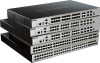
DGS-3630 Series Layer 3 Stackable Managed Switch Web UI Reference Guide between two Switches. When the 4-port stacking configuration is used, a full-duplex speed of up to 80Gbps will be available between two Switches. The figure below illustrates how Switches can be stacked in a - D-Link DGS-3630 | User Manual 1 - Page 122
DGS-3630 Series Layer 3 Stackable Managed Switch Web UI Reference Guide The figure below illustrates how Switches can be stacked in a Duplex Ring formation using optical fiber cables connected to SFP+ transceivers or DAC with SFP+ connectors where the 2-port stacking configuration is used. Figure 4- - D-Link DGS-3630 | User Manual 1 - Page 123
DGS-3630 Series Layer 3 Stackable Managed Switch Web UI Reference Guide configurations and transmit commands to remaining Switches in the Switch stack. The Primary Master can be manually from a device, or when one of the stacking ports links is down. Once the device has been removed, the remaining - D-Link DGS-3630 | User Manual 1 - Page 124
DGS-3630 Series Layer 3 Stackable Managed Switch Web UI Reference Guide If the Backup Master has been hot removed, a new Backup Master will be chosen through the election process previously described. Switches in the stack will clear the configuration of the unit removed, and dynamically learned - D-Link DGS-3630 | User Manual 1 - Page 125
to support either a 2-port or a 4-port stacking configuration. • When the 2-port stacking configuration is used, a full-duplex speed of up to 40Gbps will be used between two Switches. The DGS-3630-28TC will use physical ports 27 (SIO1) and 28 (SIO2) for 2-port stacking. The DGS-3630-28SC will - D-Link DGS-3630 | User Manual 1 - Page 126
DGS-3630 Series Layer 3 Stackable Managed Switch Web UI Reference Guide To view the following window, click Management > Stacking > Stacking Bandwidth, as shown below: Figure 4-87 Stacking Bandwidth Window The fields that can be configured a Switch that has a physical link to the SIM group but has - D-Link DGS-3630 | User Manual 1 - Page 127
DGS-3630 Series Layer 3 Stackable Managed Switch Web UI Reference Guide The SIM group is a group of Switches that are managed as a single entity. The Switch may take on three different roles: 1. Commander Switch (CS) - This is a Switch that has been manually configured as the controlling device for - D-Link DGS-3630 | User Manual 1 - Page 128
DGS-3630 Series Layer 3 Stackable Managed Switch Web UI Reference Guide The topology map now includes new features for connections that are a member of a port trunking group. It will display the speed and number of Ethernet connections creating this port trunk group. This version will support Switch - D-Link DGS-3630 | User Manual 1 - Page 129
DGS-3630 Series Layer 3 Stackable Managed Switch Web UI Reference Guide Parameter Description • Candidate - A Candidate folder will then contain four added links to aid in configuring SIM through the Web UI, including Topology, Firmware Upgrade, Configuration File Backup/Restore and Upload Log - D-Link DGS-3630 | User Manual 1 - Page 130
DGS-3630 Series Layer 3 Stackable Managed Switch Web UI Reference Guide To view the following window, click Management > SIM topology map to any of the printers configured on the PC accessing the Web UI. Preference Select this option to configure the display properties for the SIM topology map. - D-Link DGS-3630 | User Manual 1 - Page 131
DGS-3630 Series Layer 3 Stackable Managed Switch Web UI Reference Guide The fields that can be configured are described below: Parameter Interval Show All Show Member Only Description Enter the SIM topology display refresh interval value here. The range is from 10 - D-Link DGS-3630 | User Manual 1 - Page 132
DGS-3630 Series Layer 3 Stackable Managed Switch Web UI Reference Guide Topology Under View, select Topology to view the following: Figure 4-92 View > Topology Click the Zoom In button enlarge the size of the displayed items. - D-Link DGS-3630 | User Manual 1 - Page 133
DGS-3630 Series Layer 3 Stackable Managed Switch Web UI Reference Guide Tool Tips In the Topology view window, the mouse plays an important role in configuration and in viewing device information. Hover the mouse pointer over a specific device in the Topology window to display more information about - D-Link DGS-3630 | User Manual 1 - Page 134
DGS-3630 Series Layer 3 Stackable Managed Switch Web UI Reference Guide Figure 4-95 Group Property Figure 4-96 Speed Description Displays the Device Name of the Switches in the SIM group configured. If the device is not configured with a name, it will be given the name default and tagged with - D-Link DGS-3630 | User Manual 1 - Page 135
DGS-3630 Series Layer 3 Stackable Managed Switch Web UI Reference Guide Firmware Upgrade This window is used Upgrade, as shown below: Figure 4-100 Firmware Upgrade Window The fields that can be configured are described below: Parameter TFTP Server IP Path \ Filename Description Enter the TFTP - D-Link DGS-3630 | User Manual 1 - Page 136
DGS-3630 Series Layer 3 Stackable Managed Switch Web UI Reference Guide Parameter Path \ Filename Description Enter the path and file name. Click the Restore button to update the configuration from a TFTP server to the member Switch. Click the Backup button to back up the configuration file to a - D-Link DGS-3630 | User Manual 1 - Page 137
DGS-3630 Series Layer 3 Stackable Managed Switch Web UI Reference Guide To view the following window, click Management > D-Link Discovery Protocol, as shown below: Figure 4-103 D-Link Discovery Protocol Window The fields that can be configured in D-Link Discovery Protocol are described below: - D-Link DGS-3630 | User Manual 1 - Page 138
DGS-3630 Series Layer 3 Stackable Managed Switch Web UI Reference Guide To view the following window, click Management > SMTP Settings, as shown below: Figure 4-104 SMTP Settings Window The fields that can be configured in SMTP Global Settings are described below: Parameter SMTP IP SMTP IPv4 - D-Link DGS-3630 | User Manual 1 - Page 139
DGS-3630 Series Layer 3 Stackable Managed Switch Web UI Reference Guide The fields that can be configured in SMTP Mail Receiver Address shutdown, the reboot schedule will be deleted automatically. If the Switch was manually rebooted or powered off, before the reboot schedule could take effect, the - D-Link DGS-3630 | User Manual 1 - Page 140
DGS-3630 Series Layer 3 Stackable Managed Switch Web UI Reference Guide configure the Network Load Balancing (NLB) FDB settings. The Network Load Balancing (NLB) function is used to support entry won't take effect. NOTE: Link Aggregation cannot be configured across multiple Switch units in the stack - D-Link DGS-3630 | User Manual 1 - Page 141
DGS-3630 Series Layer 3 Stackable Managed Switch Web UI Reference Guide Parameter MAC Address Unit From Port - To shown below: Figure 4-107 SD Card Backup Settings Window The fields that can be configured are described below: Parameter Backup Entry Name Time Range Type Description Enter the name - D-Link DGS-3630 | User Manual 1 - Page 142
DGS-3630 Series Layer 3 Stackable Managed Switch Web UI Reference Guide Click the Edit button to configure the specific entry. Click the to display and configure the SD card execution settings. This is used to execute the configuration from the SD card to the Switch file system manually. To view the - D-Link DGS-3630 | User Manual 1 - Page 143
DGS-3630 Series Layer 3 Stackable Managed Switch Web UI Reference Guide Parameter File Name State Description to locate a specific entry based on the information entered. Click the Edit button to configure the specific entry. Click the Delete button to remove the specific entry. Enter a page - D-Link DGS-3630 | User Manual 1 - Page 144
DGS-3630 Series Layer 3 Stackable Managed Switch Web UI Reference Guide 5. Layer 2 Features FDB VLAN VLAN Tunnel STP ERPS (G.8032) Loopback Detection Link Aggregation Flex Links the stacking unit ID of the Switch that will be configured here. After selecting the Port option, select the port number - D-Link DGS-3630 | User Manual 1 - Page 145
DGS-3630 Series Layer 3 Stackable Managed Switch Web UI Reference Guide Multicast Static FDB This window is used to display and configure the multicast static FDB settings. To view the following window, click L2 Features > FDB > Static FDB > Multicast Static FDB, as shown below: Figure 5-2 - D-Link DGS-3630 | User Manual 1 - Page 146
DGS-3630 Series Layer 3 Stackable Managed Switch Web UI Reference Guide The fields that can be configured are described Table Settings (MAC Address Port Learning Settings) Window The fields that can be configured are described below: Parameter Unit From Port - To Port Status Description Select - D-Link DGS-3630 | User Manual 1 - Page 147
DGS-3630 Series Layer 3 Stackable Managed Switch Web UI Reference Guide After selecting the MAC Address VLAN Learning Settings tab VID List Status Description Enter the VLAN ID(s) that will be used in this configuration or display here. A series of VLAN IDs can be entered separated by commas or - D-Link DGS-3630 | User Manual 1 - Page 148
DGS-3630 Series Layer 3 Stackable Managed Switch Web UI Reference Guide To view the following window, click L2 Features > FDB > MAC Address Table, as shown below: Figure 5-6 MAC Address Table Window The fields that can be configured are described below: Parameter Port VID MAC Address Description - D-Link DGS-3630 | User Manual 1 - Page 149
DGS-3630 Series Layer 3 Stackable Managed Switch Web UI Reference Guide To view the following window, click L2 Features > FDB > MAC Notification, as shown below: Figure 5-7 MAC Notification (MAC Notification Settings) Window The fields that can be configured are described below: Parameter - D-Link DGS-3630 | User Manual 1 - Page 150
DGS-3630 Series Layer 3 Stackable Managed Switch Web UI Reference Guide On this page, a list of MAC notification messages will be displayed. VLAN 802.1Q VLAN This window is used to display and configure the VLAN settings on this Switch. To view the following window, click L2 Features > VLAN > 802.1Q - D-Link DGS-3630 | User Manual 1 - Page 151
DGS-3630 Series Layer 3 Stackable Managed Switch Web UI Reference Guide same physical port. For example, it allows the user to configure .3 LLC, this is a 2-octet IEEE 802.2 Link Service Access Point (LSAP) pair. The first octet is for Destination Service Access Point (DSAP) and the second octet is - D-Link DGS-3630 | User Manual 1 - Page 152
DGS-3630 Series Layer 3 Stackable Managed Switch Web UI Reference Guide The fields that can be configured are described below: Parameter Port Profile ID VID Priority Description Select the stacking unit ID and the port number of the Switch that will be configured 802.1ad service provider GVRP - D-Link DGS-3630 | User Manual 1 - Page 153
DGS-3630 Series Layer 3 Stackable Managed Switch Web UI Reference Guide To view the following window, click L2 Features > VLAN > GVRP > GVRP Port, as shown below: Figure 5-13 GVRP Port Window The fields that can be configured are described below: Parameter Unit From Port - To Port GVRP Status - D-Link DGS-3630 | User Manual 1 - Page 154
DGS-3630 Series Layer 3 Stackable Managed Switch Web UI Reference Guide To view the following window, click L2 Features > VLAN > GVRP > GVRP Advertise VLAN, as shown below: Figure 5-14 GVRP Advertise VLAN Window The fields that can be configured are described below: Parameter Unit From Port - To - D-Link DGS-3630 | User Manual 1 - Page 155
DGS-3630 Series Layer 3 Stackable Managed Switch Web UI Reference Guide The fields that can be configured are described below: Parameter Unit From Port - To Port Action Forbidden VID List Description Select the Switch unit that will be used for this configuration here. Select the range of ports - D-Link DGS-3630 | User Manual 1 - Page 156
DGS-3630 Series Layer 3 Stackable Managed Switch Web UI Reference Guide To view the following window, click L2 Features > VLAN > Asymmetric VLAN, as shown below: Figure 5-17 Asymmetric VLAN Window The fields that can be configured are described below: Parameter Asymmetric VLAN State Description - D-Link DGS-3630 | User Manual 1 - Page 157
DGS-3630 Series Layer 3 Stackable Managed Switch Web UI Reference Guide To view the following window, click L2 Features > VLAN > VLAN Interface, as shown below: Figure 5-19 VLAN Interface Window The fields that can be configured are described below: Parameter Unit Description Select the Switch - D-Link DGS-3630 | User Manual 1 - Page 158
DGS-3630 Series Layer 3 Stackable Managed Switch Web UI Reference Guide After click the Edit button, the following Select to enable or disable the ingress checking function. Enter the VLAN ID used for this configuration here. This value must be between 1 and 4094. Select this option to enable the - D-Link DGS-3630 | User Manual 1 - Page 159
DGS-3630 Series Layer 3 Stackable Managed Switch Web UI Reference Guide The fields that can be configured are described below: VLAN option the following parameter will be available. Enter the VLAN ID used for this configuration here. This value must be between 1 and 4094. Select the action that will - D-Link DGS-3630 | User Manual 1 - Page 160
DGS-3630 Series Layer 3 Stackable Managed Switch Web UI Reference Guide Parameter Native VLAN VID Action Allowed VLAN Range Clone From Port - To Port Description Tick this option to enable the native VLAN function. Also select if this VLAN supports ID used for this configuration here. This value - D-Link DGS-3630 | User Manual 1 - Page 161
DGS-3630 Series Layer 3 Stackable Managed Switch Web UI Reference Guide Parameter From Port - To Port page will appear. Figure 5-26 VLAN Interface (Host) Window The fields that can be configured are described below: Parameter VLAN Mode Description Select the VLAN mode option here. Options to - D-Link DGS-3630 | User Manual 1 - Page 162
DGS-3630 Series Layer 3 Stackable Managed Switch Web UI Reference Guide Parameter Acceptable Frame Ingress Checking this VLAN supports Untagged or Tagged frames. After ticking the Native VLAN option the following parameter will be available. Enter the VLAN ID used for this configuration here. This - D-Link DGS-3630 | User Manual 1 - Page 163
DGS-3630 Series Layer 3 Stackable Managed Switch Web UI Reference Guide When Trunk Secondary was selected as the VLAN Mode, the following page will appear. Figure 5-28 VLAN Interface (Trunk Secondary) Window The fields that can be configured are described below: Parameter VLAN Mode Acceptable - D-Link DGS-3630 | User Manual 1 - Page 164
DGS-3630 Series Layer 3 Stackable Managed Switch Web UI Reference Guide To view the following window, click L2 Features > VLAN > L2VLAN Interface Description, as shown below: Figure 5-29 L2VLAN Interface Description Window The fields that can be configured are described below: Parameter L2VLAN - D-Link DGS-3630 | User Manual 1 - Page 165
DGS-3630 Series Layer 3 Stackable Managed Switch Web UI Reference Guide The fields that can be configured are described below: , as shown below: Figure 5-31 Super VLAN Window The fields that can be configured in Add Super VLAN are described below: Parameter Super VID List Description Enter the - D-Link DGS-3630 | User Manual 1 - Page 166
DGS-3630 Series Layer 3 Stackable Managed Switch Web UI Reference Guide The fields that can be configured in Add Sub VLAN are described below entry or to remove the sub-VLAN from the super VLAN. Click the IP Range List link to add an IP range to the sub-VLAN. Enter a page number and click the Go - D-Link DGS-3630 | User Manual 1 - Page 167
DGS-3630 Series Layer 3 Stackable Managed Switch Web UI Reference Guide Auto Surveillance VLAN Auto Surveillance Properties This window is used to display and configure the VLAN as a surveillance VLAN. Enter the Class of Service (CoS) value for the surveillance VLAN here. The surveillance packets - D-Link DGS-3630 | User Manual 1 - Page 168
DGS-3630 Series Layer 3 Stackable Managed Switch Web UI Reference Guide The fields that can be configured in Port Settings are described below: Parameter Unit From Port - To Port State Description Select the Switch unit that will be used for this configuration here. Select the range of ports that - D-Link DGS-3630 | User Manual 1 - Page 169
DGS-3630 Series Layer 3 Stackable Managed Switch Web UI Reference Guide Parameter Mask Description Enter the matching this display here. Voice VLAN Voice VLAN Global This window is used to display and configure the global voice VLAN settings. This is used to enable the global voice VLAN function - D-Link DGS-3630 | User Manual 1 - Page 170
DGS-3630 Series Layer 3 Stackable Managed Switch Web UI Reference Guide traffic in Quality of Service. Enter the aging time value here. This is used to configure the aging time for automatically learned. • Manual - Specifies that voice VLAN membership will be manually configured. If auto-learning - D-Link DGS-3630 | User Manual 1 - Page 171
DGS-3630 Series Layer 3 Stackable Managed Switch Web UI Reference Guide Parameter Description is working in the auto-tagged button to accept the changes made. Voice VLAN OUI This window is used to display and configure the voice VLAN OUI settings. Use this window to add a user-defined OUI for the - D-Link DGS-3630 | User Manual 1 - Page 172
DGS-3630 Series Layer 3 Stackable Managed Switch Web UI Reference Guide Voice VLAN Device This window is used to view the voice VLAN device table. To view the following 5-40 Voice VLAN LLDP-MED Device Window Private VLAN This window is used to display and configure the private VLAN settings. 160 - D-Link DGS-3630 | User Manual 1 - Page 173
DGS-3630 Series Layer 3 Stackable Managed Switch Web UI Reference Guide To view the following window, click L2 Features > VLAN > Private VLAN, as shown below: Figure 5-41 Private VLAN Window The fields that can be configured for Private VLAN are described below: Parameter VID List State Type - D-Link DGS-3630 | User Manual 1 - Page 174
DGS-3630 Series Layer 3 Stackable Managed Switch Web UI Reference Guide Click the Apply button to accept the changes made. The fields that can be configured , which receives and transmits the service VLAN tagged frames. If the tunnel Ethernet type is configured, the specified value will be the - D-Link DGS-3630 | User Manual 1 - Page 175
DGS-3630 Series Layer 3 Stackable Managed Switch Web UI Reference Guide The fields that can be configured are described below: Parameter Inner the priority of the VLAN tag in the received packets will be copied to the service VLAN tag. Select to enable or disable the Miss Drop feature here. If the - D-Link DGS-3630 | User Manual 1 - Page 176
DGS-3630 Series Layer 3 Stackable Managed Switch Web UI Reference Guide VLAN Mapping This window is used to display and configure the VLAN mapping settings. If a profile is applied on an interface . Options to choose from are: • Copy - Specifies that a copy of the service VLAN priority is used. 164 - D-Link DGS-3630 | User Manual 1 - Page 177
DGS-3630 Series Layer 3 Stackable Managed Switch Web UI Reference Guide Parameter Description • 0 to 7 - Specifies the when multiple pages exist. VLAN Mapping Profile This window is used to display and configure the VLAN mapping profile settings. To view the following window, click L2 Features > - D-Link DGS-3630 | User Manual 1 - Page 178
DGS-3630 Series Layer 3 Stackable Managed Switch Web UI Reference Guide After clicking the Add Rule button next to an Ethernet type profile, the following page will appear. Figure 5-46 VLAN Mapping Profile (Ethernet, Add Rule) Window The fields that can be configured are described below: - D-Link DGS-3630 | User Manual 1 - Page 179
DGS-3630 Series Layer 3 Stackable Managed Switch Web UI Reference Guide After clicking the Add Rule button next to an IP type profile, the following page will appear. Figure 5-47 VLAN Mapping Profile (IP, Add Rule) Window The fields that can be configured are described below: Parameter Rule ID - D-Link DGS-3630 | User Manual 1 - Page 180
DGS-3630 Series Layer 3 Stackable Managed Switch Web UI Reference Guide After clicking the Add Rule button next to an IPv6 type profile, the following page will appear. Figure 5-48 VLAN Mapping Profile (IPv6, Add Rule) Window The fields that can be configured are described below: Parameter Rule - D-Link DGS-3630 | User Manual 1 - Page 181
DGS-3630 Series Layer 3 Stackable Managed Switch Web UI Reference Guide After clicking the Add Rule button next to an Ethernet-IP type profile, the following page will appear. Figure 5-49 VLAN Mapping Profile (Ethernet-IP, Add Rule) Window The fields that can be configured are described below: - D-Link DGS-3630 | User Manual 1 - Page 182
DGS-3630 Series Layer 3 Stackable Managed Switch Web UI Reference Guide 802.1Q-2005 MSTP have been recently introduced to D-Link managed Ethernet Switches, a brief introduction to the the MST Configuration Identification window), which will associate each of the possible 4094 VLANs supported by the - D-Link DGS-3630 | User Manual 1 - Page 183
DGS-3630 Series Layer 3 Stackable Managed Switch Web UI Reference Guide link between bridges is sensitive to the status of the link. Ultimately this difference results in faster detection of failed links considered to be P2P ports unless manually overridden through configuration. 802.1D-1998/802.1D- - D-Link DGS-3630 | User Manual 1 - Page 184
DGS-3630 Series Layer 3 Stackable Managed Switch Web UI Reference Guide The Spanning Tree Protocol (STP) operates on two Click the Apply button to accept the changes made. The fields that can be configured for STP Traps are described below: Parameter STP New Root Trap STP Topology Change Trap - D-Link DGS-3630 | User Manual 1 - Page 185
DGS-3630 Series Layer 3 Stackable Managed Switch Web UI Reference Guide The fields that can be configured for STP Priority are described below: Parameter Priority Description Select the STP priority value here. This value is between 0 and 61440. By default, this value - D-Link DGS-3630 | User Manual 1 - Page 186
DGS-3630 Series Layer 3 Stackable Managed Switch Web UI Reference Guide To view the following window, click L2 Features > STP > STP Port Settings, as shown below: Figure 5-51 STP Port Settings Window The fields that can be configured Guard Root function. Select the link type here. Options to choose - D-Link DGS-3630 | User Manual 1 - Page 187
DGS-3630 Series Layer 3 Stackable Managed Switch Web UI Reference Guide Parameter TCN Filter BPDU Forward Priority the interval that a designated port will wait between the periodic transmissions of each configuration message. Select to enable or disable the Loop Guard feature on the specified port - D-Link DGS-3630 | User Manual 1 - Page 188
DGS-3630 Series Layer 3 Stackable Managed Switch Web UI Reference Guide The fields that can be configured for MST Configuration Identification are described below: Parameter Configuration Name Revision Level Description Enter the MST. This name uniquely identifies the MSTI (Multiple Spanning Tree - D-Link DGS-3630 | User Manual 1 - Page 189
DGS-3630 Series Layer 3 Stackable Managed Switch Web UI Reference Guide The fields that can be configured are described below: Parameter One link within a ring will be blocked to avoid a Loop (RPL, Ring Protection Link). When the failure happens, protection switching blocks the failed link and - D-Link DGS-3630 | User Manual 1 - Page 190
ERPS DGS-3630 Series Layer 3 Stackable Managed Switch Web UI Reference Guide This window is used to display and configure the Ethernet following functions: • Supports multi-instance in a physical ring. • Supports operation commands: manual, force, and clear. • Supports to configure the sending of - D-Link DGS-3630 | User Manual 1 - Page 191
DGS-3630 Series Layer 3 Stackable Managed Switch Web UI Reference Guide Parameter Description • Manual switch or force switch command must not exist. • The physical ring must have only one instance. Click the Apply button to accept the changes made. The fields that can be configured in Ethernet - D-Link DGS-3630 | User Manual 1 - Page 192
DGS-3630 Series Layer 3 Stackable Managed Switch Web UI Reference Guide Parameter Ring ID Ring Type Description Select the checkbox and enter the ring ID here. The range is from 1 to 239. Select the Specify radio button to configure this parameter as normal. Select the None radio button to revert - D-Link DGS-3630 | User Manual 1 - Page 193
DGS-3630 Series Layer 3 Stackable Managed Switch Web UI Reference Guide After click the Edit Instance button, the following window will appear. Figure 5-59 ERPS (ERPS Brief, Edit Instance) Window The fields that can be configured are described below: Parameter Description R-APS Channel VLAN - D-Link DGS-3630 | User Manual 1 - Page 194
DGS-3630 Series Layer 3 Stackable Managed Switch Web UI Reference Guide Parameter Activate Sub Ring Instance Force Ring Port Block Manual Ring Port Block Description Specify radio button to configure blocks a port on which MS is configured when link failures and FS conditions are absent. Options - D-Link DGS-3630 | User Manual 1 - Page 195
DGS-3630 Series Layer 3 Stackable Managed Switch Web UI Reference Guide After click the Edit button, the following window will appear. Figure 5-61 ERPS Profile (Edit) Window The fields that can be configured are described below: Parameter TCN Propagation Revertive Guard Timer Hold-Off Timer WTR - D-Link DGS-3630 | User Manual 1 - Page 196
DGS-3630 Series Layer 3 Stackable Managed Switch Web UI Reference Guide To view the following window, click L2 Features > Loopback Detection, as shown below: Figure 5-62 Loopback Detection Window The fields that can be configured in Loopback Detection Global Settings are described below: - D-Link DGS-3630 | User Manual 1 - Page 197
DGS-3630 Series Layer 3 Stackable Managed Switch Web UI Reference Guide Link Aggregation Understanding Port Trunk Groups Port trunk groups are used to combine a number of ports together to make a single high-bandwidth data pipeline. The Switch supports up to 32 port trunk groups with up to 12 ports - D-Link DGS-3630 | User Manual 1 - Page 198
DGS-3630 Series Layer 3 Stackable Managed Switch Web UI Reference Guide This window is used to display and configure the link aggregation settings. To view the following window, click L2 Features > Link Aggregation, as shown below: Figure 5-64 Link Aggregation Window The fields that can be - D-Link DGS-3630 | User Manual 1 - Page 199
DGS-3630 Series Layer 3 Stackable Managed Switch Web UI Reference Guide After clicking the Show Detail button, the following page will be available. Figure 5-65 Link Aggregation (Channel Detail) Window The fields that can be configured are described below: Parameter Description Description Enter - D-Link DGS-3630 | User Manual 1 - Page 200
DGS-3630 Series Layer 3 Stackable Managed Switch Web UI Reference Guide Two identical Switches running on the same firmware version must be used to create the MLAG peer connection. The following settings must be identical on MLAG peer switches to prevent instability: Link can be configured are - D-Link DGS-3630 | User Manual 1 - Page 201
DGS-3630 Series Layer 3 Stackable Managed Switch Web UI Reference Guide The fields that can be configured in MLAG State are number that will be used here. Select this option to configure the selected port as a peer-link port. Peer-links are used to create a connection between MLAG peer Switches. - D-Link DGS-3630 | User Manual 1 - Page 202
DGS-3630 Series Layer 3 Stackable Managed Switch Web UI Reference Guide To view the following window, click L2 Features > MLAG > MLAG Group, as shown below: Figure 5-68 MLAG Group Window The fields that can be configured are described below: Parameter MLAG Group ID Description Enter the MLAG - D-Link DGS-3630 | User Manual 1 - Page 203
DGS-3630 Series Layer 3 Stackable Managed Switch Web UI Reference Guide The fields that can be configured are described below: specific entry. NOTE: Flex Link and STP, ERPS and LBD are mutually exclusive. L2 Protocol Tunnel This window is used to display and configure the Layer 2 protocol tunnel - D-Link DGS-3630 | User Manual 1 - Page 204
DGS-3630 Series Layer 3 Stackable Managed Switch Web UI Reference Guide Parameter Action Tunneled Protocol Protocol MAC Protocol Tunnel (L2 Protocol Tunnel Port Setting) Window The fields that can be configured are described below: Parameter Unit From Port - To Port Action Type Tunneled Protocol - D-Link DGS-3630 | User Manual 1 - Page 205
DGS-3630 Series Layer 3 Stackable Managed Switch Web UI Reference Guide Click the Clear All button to clear snooping. Click the Apply button to accept the changes made. The fields that can be configured in VLAN Status Settings are described below: Parameter VID Description Enter a VLAN ID from - D-Link DGS-3630 | User Manual 1 - Page 206
DGS-3630 Series Layer 3 Stackable Managed Switch Web UI Reference Guide The fields that can be configured in IGMP Snooping Table are to see the detail information of the specific VLAN. Click the Edit button to re-configure the specific entry. Enter a page number and click the Go button to navigate - D-Link DGS-3630 | User Manual 1 - Page 207
DGS-3630 Series Layer 3 Stackable Managed Switch Web UI Reference Guide After clicking the Modify or Edit button in IGMP Snooping Settings window, the following window will appear. Figure 5-74 IGMP Snooping Settings (Modify, Edit) Window The fields that can be configured are described below: - D-Link DGS-3630 | User Manual 1 - Page 208
DGS-3630 Series Layer 3 Stackable Managed Switch Web UI Reference Guide Parameter Proxy Reporting Source Address RADIUS. Click the Apply button to accept the changes made. The fields that can be configured in IGMP Snooping AAA Table are described below: Parameter Unit From Port - To Port - D-Link DGS-3630 | User Manual 1 - Page 209
DGS-3630 Series Layer 3 Stackable Managed Switch Web UI Reference Guide IGMP Snooping Groups Settings This window is used to display and configure the IGMP snooping static group, and view IGMP snooping group. To view the following window, click L2 Features > L2 Multicast Control > IGMP Snooping > - D-Link DGS-3630 | User Manual 1 - Page 210
DGS-3630 Series Layer 3 Stackable Managed Switch Web UI Reference Guide Parameter Detail Description Select this Port option was selected as the action below. Enter the limit number here. This is to configure the rate of IGMP control packets that the Switch can process on a specific interface. The - D-Link DGS-3630 | User Manual 1 - Page 211
DGS-3630 Series Layer 3 Stackable Managed Switch Web UI Reference Guide Parameter Action VID Description Select the action Click the Apply button to accept the changes made. The fields that can be configured in IGMP Snooping Limit Settings are described below: Parameter Unit From Port - To Port - D-Link DGS-3630 | User Manual 1 - Page 212
DGS-3630 Series Layer 3 Stackable Managed Switch Web UI Reference Guide The fields that can be configured in IGMP Snooping Filter Table are described below: Parameter Unit From Port - To Port Description Select the Switch unit ID that will be used here. - D-Link DGS-3630 | User Manual 1 - Page 213
DGS-3630 Series Layer 3 Stackable Managed Switch Web UI Reference Guide To view the following window, click L2 Features > L2 Multicast Control > IGMP Snooping > IGMP Snooping Mrouter Settings, as shown below: Figure 5-80 IGMP Snooping Mrouter Settings Window The fields that can be configured in - D-Link DGS-3630 | User Manual 1 - Page 214
DGS-3630 Series Layer 3 Stackable Managed Switch Web UI Reference Guide To view the following window, click L2 Features > L2 Multicast Control > IGMP Snooping > IGMP Snooping Statistics Settings, as shown below: Figure 5-81 IGMP Snooping Statistics Settings Window The fields that can be configured - D-Link DGS-3630 | User Manual 1 - Page 215
DGS-3630 Series Layer 3 Stackable Managed Switch Web UI Reference Guide this message is sent by the router to ask if any link is requesting multicast data. There are two types of MLD Snooping Settings This window is used to display and configure the MLD snooping settings. To view the following window - D-Link DGS-3630 | User Manual 1 - Page 216
DGS-3630 Series Layer 3 Stackable Managed Switch Web UI Reference Guide The fields that can be configured in Global Settings are described below: Parameter Global State Description Select this option to enable or disable the global MLD snooping state. Click the Apply - D-Link DGS-3630 | User Manual 1 - Page 217
DGS-3630 Series Layer 3 Stackable Managed Switch Web UI Reference Guide After clicking the Modify or Edit button in MLD Snooping Settings window, the following window will appear. Figure 5-84 MLD Snooping Settings (Modify, Edit) Window The fields that can be configured are described below: - D-Link DGS-3630 | User Manual 1 - Page 218
DGS-3630 Series Layer 3 Stackable Managed Switch Web UI Reference Guide Parameter Rate Limit Ignore Topology Change the changes made. MLD Snooping Groups Settings This window is used to display and configure the MLD snooping static group, and view MLD snooping group. To view the following - D-Link DGS-3630 | User Manual 1 - Page 219
DGS-3630 Series Layer 3 Stackable Managed Switch Web UI Reference Guide The fields that can be configured in MLD Snooping Groups all the entries. MLD Snooping Filter Settings This window is used to display and configure the MLD snooping settings. To view the following window, click L2 Features > - D-Link DGS-3630 | User Manual 1 - Page 220
DGS-3630 Series Layer 3 Stackable Managed Switch Web UI Reference Guide Parameter Limit Number Action VID Description Enter the limit number here. This is to configure the rate of MLD control packets that the Switch can process on a specific interface. The range is from 1 to 1000 packets per - D-Link DGS-3630 | User Manual 1 - Page 221
DGS-3630 Series Layer 3 Stackable Managed Switch Web UI Reference Guide The fields that can be configured in MLD Snooping Filter exist. MLD Snooping Mrouter Settings This window is used to display and configure the specified interface(s) as the router ports or forbidden to be IPv6 multicast router - D-Link DGS-3630 | User Manual 1 - Page 222
DGS-3630 Series Layer 3 Stackable Managed Switch Web UI Reference Guide To view the following window, click L2 Features > L2 Multicast Control > MLD Snooping > MLD Snooping Mrouter Settings, as shown below: Figure 5-89 MLD Snooping Mrouter Settings Window The fields that can be configured in MLD - D-Link DGS-3630 | User Manual 1 - Page 223
DGS-3630 Series Layer 3 Stackable Managed Switch Web UI Reference Guide To view the following window, click L2 Features > L2 Multicast Control > MLD Snooping > MLD Snooping Statistics Settings, as shown below: Figure 5-90 MLD Snooping Statistics Settings Window The fields that can be configured in - D-Link DGS-3630 | User Manual 1 - Page 224
DGS-3630 Series Layer 3 Stackable Managed Switch Web UI Reference Guide To view the following window, click L2 Features > L2 Multicast Control > Multicast VLAN > Multicast VLAN Settings, as shown below: Figure 5-91 Multicast VLAN Settings Window The fields that can be configured in Multicast VLAN - D-Link DGS-3630 | User Manual 1 - Page 225
DGS-3630 Series Layer 3 Stackable Managed Switch Web UI Reference Guide Click the Delete button to delete an entry based on the information entered. Click the Add button to add a new entry based on the information entered. The fields that can be configured in Member Port Settings are described - D-Link DGS-3630 | User Manual 1 - Page 226
DGS-3630 Series Layer 3 Stackable Managed Switch Web UI Reference Guide Parameter IP Address From Description Enter Click the Apply button to accept the changes made. The fields that can be configured in Multicast VLAN Table are described below: Parameter VID Description Enter the multicast VLAN - D-Link DGS-3630 | User Manual 1 - Page 227
DGS-3630 Series Layer 3 Stackable Managed Switch Web UI Reference Guide To view the following window, click L2 Features > L2 Multicast Control > Multicast VLAN > Multicast VLAN Group Settings, as shown below: Figure 5-92 Multicast VLAN Group Settings Window The fields that can be configured in - D-Link DGS-3630 | User Manual 1 - Page 228
DGS-3630 Series Layer 3 Stackable Managed Switch Web UI Reference Guide Parameter Action Description to navigate to a specific page when multiple pages exist. The fields that can be configured in Access Group Table are described below: Parameter VID Description Enter the multicast VLAN ID - D-Link DGS-3630 | User Manual 1 - Page 229
DGS-3630 Series Layer 3 Stackable Managed Switch Web UI Reference Guide The fields that can be configured in Global Settings are described below: Parameter Global State Description Select to globally enable or disable the PIM snooping feature here. Click the Apply button - D-Link DGS-3630 | User Manual 1 - Page 230
DGS-3630 Series Layer 3 Stackable Managed Switch Web UI Reference Guide To view the following window, click L2 Features > L2 Multicast Control > PIM Snooping > PIM Snooping Mroute Table, as shown below: Figure 5-95 PIM Snooping Mroute Table Window The fields that can be configured are described - D-Link DGS-3630 | User Manual 1 - Page 231
DGS-3630 Series Layer 3 Stackable Managed Switch Web UI Reference Guide Multicast Filtering Mode This window is used to display and configure the Layer 2 multicast filtering settings. To view the following window, click L2 Features > L2 Multicast Control > Multicast Filtering Mode, as shown below: - D-Link DGS-3630 | User Manual 1 - Page 232
DGS-3630 Series Layer 3 Stackable Managed Switch Web UI Reference Guide To view the following window, click L2 Features > LLDP > LLDP Global Settings, as shown below: Figure 5-98 LLDP Global Settings Window The fields that can be configured in LLDP Global Settings are described below: Parameter - D-Link DGS-3630 | User Manual 1 - Page 233
DGS-3630 Series Layer 3 Stackable Managed Switch Web UI Reference Guide The fields that can be configured in LLDP Configurations are described below: Parameter Message TX Interval Message TX Hold Multiplier ReInit Delay TX Delay Description Enter the interval between consecutive transmissions of - D-Link DGS-3630 | User Manual 1 - Page 234
DGS-3630 Series Layer 3 Stackable Managed Switch Web UI Reference Guide Parameter IP Subtype Action Address Description data in its outbound advertisements. There are four optional data types that can be configured to exclude one or more of these data types from outbound LLDP advertisements. The - D-Link DGS-3630 | User Manual 1 - Page 235
DGS-3630 Series Layer 3 Stackable Managed Switch Web UI Reference Guide To view the following window, click L2 Features > LLDP > LLDP Basic TLVs Settings, as shown below: Figure 5-101 LLDP Basic TLVs Settings Window The fields that can be configured are described below: Parameter Unit From Port - - D-Link DGS-3630 | User Manual 1 - Page 236
DGS-3630 Series Layer 3 Stackable Managed Switch Web UI Reference Guide The fields that can be configured are described below: Parameter Unit From Port - To Port Port VLAN Protocol VLAN VLAN Name Protocol Identity Description Select the Switch unit that will be used for this configuration here. - D-Link DGS-3630 | User Manual 1 - Page 237
DGS-3630 Series Layer 3 Stackable Managed Switch Web UI Reference Guide Parameter Link link for connected non-powered systems. The Power Via MDI TLV allows network management to advertise and discover the MDI power support The fields that can be configured are described below: Parameter Unit - D-Link DGS-3630 | User Manual 1 - Page 238
DGS-3630 Series Layer 3 Stackable Managed Switch Web UI Reference Guide Parameter Capabilities Inventory Network Policy to enable or disable the Priority-based Flow Control (PFC) configuration TLV feature here. This specifies the PFC Configuration TLV to be sent. The PFC TLV is an optional TLV - D-Link DGS-3630 | User Manual 1 - Page 239
DGS-3630 Series Layer 3 Stackable Managed Switch Web UI Reference Guide To view the following window, click L2 Features > LLDP > LLDP Statistics Information, as shown below: Figure 5-106 LLDP Statistics Information Window The fields that can be configured are described below: Parameter Unit Port - D-Link DGS-3630 | User Manual 1 - Page 240
DGS-3630 Series Layer 3 Stackable Managed Switch Web UI Reference Guide The fields that can be configured are described below: Parameter Unit Port Description Select the Switch unit that will be displayed. Select the port number that will be displayed. Click the - D-Link DGS-3630 | User Manual 1 - Page 241
DGS-3630 Series Layer 3 Stackable Managed Switch Web UI Reference Guide After clicking the Show Detail hyperlink, a below: Figure 5-110 LLDP Neighbor Port Information Window The fields that can be configured are described below: Parameter Unit Port Description Select the Switch unit that will be - D-Link DGS-3630 | User Manual 1 - Page 242
DGS-3630 Series Layer 3 Stackable Managed Switch Web UI Reference Guide Click the Clear button to clear the specific port Detail) Window To view more details about, for example, the MAC/PHY Configuration/Status, click the Show Detail hyperlink. Click the Back button to return to the previous window - D-Link DGS-3630 | User Manual 1 - Page 243
DGS-3630 Series Layer 3 Stackable Managed Switch Web UI Reference Guide After clicking the Show Detail hyperlink, a new section will appear at the bottom of the window. Figure 5-112 LLDP Neighbor Port Information (Show Detail) Window Click the Back button to return to the previous window. 231 - D-Link DGS-3630 | User Manual 1 - Page 244
DGS-3630 Series Layer 3 Stackable Managed Switch Web UI Reference Guide 6. Layer 3 Features ARP Gratuitous ARP IPv6 Route VRRP Settings VRRPv3 Settings ARP ARP Elevation This window is used to display and configure the Address Resolution Protocol (ARP) elevation state. This is used to allow all ARP - D-Link DGS-3630 | User Manual 1 - Page 245
DGS-3630 Series Layer 3 Stackable Managed Switch Web UI Reference Guide ARP Aging Time This window is used to display and configure the ARP aging time settings. To view the following window, click L3 Features > ARP > ARP Aging Time, as shown below: Figure 6-2 ARP Aging Time Window - D-Link DGS-3630 | User Manual 1 - Page 246
DGS-3630 Series Layer 3 Stackable Managed Switch Web UI Reference Guide Click the Edit button to re-configure the specific entry. Click the Delete button to remove the specific entry. Enter a page number and click the Go button to navigate to a specific page - D-Link DGS-3630 | User Manual 1 - Page 247
DGS-3630 Series Layer 3 Stackable Managed Switch Web UI Reference Guide The fields that can be configured are described below: IP and destination IP are in the same interface. Click the Edit button to re-configure the specific entry. Click the Apply button to accept the changes made. Enter a page - D-Link DGS-3630 | User Manual 1 - Page 248
DGS-3630 Series Layer 3 Stackable Managed Switch Web UI Reference Guide Gratuitous ARP This window is used to display and configure the the Apply button to accept the changes made. Click the Edit button to re-configure the specific entry. Enter a page number and click the Go button to navigate - D-Link DGS-3630 | User Manual 1 - Page 249
DGS-3630 Series Layer 3 Stackable Managed Switch Web UI Reference Guide To view the following window, click L3 Features > IPv6 Neighbor, as shown below: Figure 6-8 IPv6 Neighbor Window The fields that can be configured are described below: Parameter Interface VLAN IPv6 Address MAC Address - D-Link DGS-3630 | User Manual 1 - Page 250
DGS-3630 Series Layer 3 Stackable Managed Switch Web UI Reference Guide Enter a page number and click the Go button to navigate to a specific page when multiple pages exist. Interface IPv4 Interface This window is used to display and configure the IPv4 interface settings. To view the following - D-Link DGS-3630 | User Manual 1 - Page 251
DGS-3630 Series Layer 3 Stackable Managed Switch Web UI Reference Guide After clicking the Edit button, the following page will be available. Figure 6-11 IPv4 Interface (Edit) Window The fields that can be configured can enter the IPv4 address of this interface manually in the fields provided. 239 - D-Link DGS-3630 | User Manual 1 - Page 252
DGS-3630 Series Layer 3 Stackable Managed Switch Web UI Reference Guide Parameter Description • When the DHCP Figure 6-12 IPv4 Interface (Edit, DHCP Client) Window The fields that can be configured are described below: Parameter DHCP Client Client-ID Class ID String Host Name Lease Description - D-Link DGS-3630 | User Manual 1 - Page 253
DGS-3630 Series Layer 3 Stackable Managed Switch Web UI Reference Guide IPv6 Interface This window is used to display and configure the IPv6 interface settings. To view the following window, click L3 Features > Interface > IPv6 Interface, as shown below: Figure 6-13 IPv6 Interface Window The - D-Link DGS-3630 | User Manual 1 - Page 254
DGS-3630 Series Layer 3 Stackable Managed Switch Web UI Reference Guide After clicking the Show Detail button, the following page will be available. Figure 6-14 IPv6 Interface (Detail, IPv6 Interface Settings) Window The fields that can be configured are described below: Parameter IPv6 MTU IPv6 - D-Link DGS-3630 | User Manual 1 - Page 255
DGS-3630 Series Layer 3 Stackable Managed Switch Web UI Reference Guide The fields that can be configured for NS Interval Settings here. The range is from 0 to 9000 seconds. The lifetime value in RA instructs the received host the lifetime value for taking the router as the default router. Select - D-Link DGS-3630 | User Manual 1 - Page 256
DGS-3630 Series Layer 3 Stackable Managed Switch Web UI Reference Guide After selecting the Neighbor Discover tab option, at Window Click the Restart button to restart the DHCPv6 client service. The fields that can be configured for DHCPv6 Client Settings are described below: Parameter Client - D-Link DGS-3630 | User Manual 1 - Page 257
DGS-3630 Series Layer 3 Stackable Managed Switch Web UI Reference Guide Loopback Interface This window is used to display and configure the loopback interface settings. A loopback interface is a software only interface which always stays in the up status. To view the following window, click L3 - D-Link DGS-3630 | User Manual 1 - Page 258
DGS-3630 Series Layer 3 Stackable Managed Switch Web UI Reference Guide Parameter IP Address Mask IPv6 Address Link entered is the link-local IPv6 address. used to display and configure the Null interface settings can be configured are described configure the IP forward protocol settings. This feature is - D-Link DGS-3630 | User Manual 1 - Page 259
DGS-3630 Series Layer 3 Stackable Managed Switch Web UI Reference Guide To view the following window, click L3 Features > UDP Helper > IP Forward Protocol, as shown below: Figure 6-21 IP Forward Protocol Window The fields that can be configured are described below: Parameter IP Forward Protocol - D-Link DGS-3630 | User Manual 1 - Page 260
DGS-3630 Series Layer 3 Stackable Managed Switch Web UI Reference Guide The fields that can be configured are described below: ARP entry already exists, an ARP request will not be sent. The Switch also supports a floating static route, which means that the user may create an alternative static route - D-Link DGS-3630 | User Manual 1 - Page 261
DGS-3630 Series Layer 3 Stackable Managed Switch Web UI Reference Guide Parameter IP Address Mask IP shown below: Figure 6-24 IPv4 Static Route BFD Window The fields that can be configured are described below: Parameter Interface Name IP Address Description Enter the name of the interface - D-Link DGS-3630 | User Manual 1 - Page 262
DGS-3630 Series Layer 3 Stackable Managed Switch Web UI Reference Guide IPv4 Route Table This window is used to display and configure the IPv4 route table settings. To view the following window, click L3 Features > IPv4 Route Table, as shown below: Figure 6-25 IPv4 Route Table Window - D-Link DGS-3630 | User Manual 1 - Page 263
DGS-3630 Series Layer 3 Stackable Managed Switch Web UI Reference Guide To view the following window, click L3 Features > IPv6 Static/Default Route, as shown below: Figure 6-26 IPv6 Static/Default Route Window The fields that can be configured are described below: Parameter IPv6 Address/Prefix - D-Link DGS-3630 | User Manual 1 - Page 264
DGS-3630 Series Layer 3 Stackable Managed Switch Web UI Reference Guide The fields that can be configured are described below: IPv6 Route Table, as shown below: Figure 6-28 IPv6 Route Table Window The fields that can be configured are described below: Parameter IPv6 Address IPv6 Address - D-Link DGS-3630 | User Manual 1 - Page 265
DGS-3630 Series Layer 3 Stackable Managed Switch Web UI Reference Guide Enter a page number and click the Go button to navigate to a specific page when multiple pages exist. Route Preference This window is used to display and configure the route preference settings. Use this window to configure the - D-Link DGS-3630 | User Manual 1 - Page 266
DGS-3630 Series Layer 3 Stackable Managed Switch Web UI Reference Guide To view the following window, click L3 Features > ECMP Settings, as shown below: Figure 6-31 ECMP Settings Window The fields that can be configured in ECMP Load Balancing Settings are described below: Parameter Destination IP - D-Link DGS-3630 | User Manual 1 - Page 267
DGS-3630 Series Layer 3 Stackable Managed Switch Web UI Reference Guide To view the following window, click L3 Features > IPv6 General Prefix, as shown below: Figure 6-32 IPv6 General Prefix Window The fields that can be configured are described below: Parameter Interface VLAN Prefix Name IPv6 - D-Link DGS-3630 | User Manual 1 - Page 268
DGS-3630 Series Layer 3 Stackable Managed Switch Web UI Reference Guide Click the Find button to locate a . Figure 6-34 IP Tunnel Settings (Edit) Window The fields that can be configured are described below: Parameter Status Description Tunnel Mode Description Select the IP tunnel interface - D-Link DGS-3630 | User Manual 1 - Page 269
DGS-3630 Series Layer 3 Stackable Managed Switch Web UI Reference Guide URPF Settings This window is used to display and configure the Unicast a number of different attack types. Unicast RPF helps to mitigate problems caused by malformed or forged IPv4/IPv6 source addresses passing through the - D-Link DGS-3630 | User Manual 1 - Page 270
DGS-3630 Series Layer 3 Stackable Managed Switch Web UI Reference Guide Click the Apply button to accept the changes made. The fields that can be configured in URPF Port Settings are described below: Parameter Unit From Port - To Port Reachable Via Description Select the Switch unit that will be - D-Link DGS-3630 | User Manual 1 - Page 271
DGS-3630 Series Layer 3 Stackable Managed Switch Web UI Reference Guide Click the Edit button to re-configure the specific entry Click the Apply button to accept the changes made. The fields that can be configured in VRF Import Map Settings are described below: Parameter Import Map Name None - D-Link DGS-3630 | User Manual 1 - Page 272
DGS-3630 Series Layer 3 Stackable Managed Switch Web UI Reference Guide The fields that can be configured in Route Distinguisher Settings are described below the previous window. After clicking the Show Detail link, the following page will appear. Figure 6-39 VRF Settings (Show Detail, Show Detail) - D-Link DGS-3630 | User Manual 1 - Page 273
DGS-3630 Series Layer 3 Stackable Managed Switch Web UI Reference Guide Click the Back button to return to the previous window. VRF Interface Settings This window is used to display and configure the VRF interface settings. To view the following window, click L3 Features > VRF > VRF Interface - D-Link DGS-3630 | User Manual 1 - Page 274
DGS-3630 Series Layer 3 Stackable Managed Switch Web UI Reference Guide RIP RIP Settings This window is used to display and configure Routing Information Protocol (RIP) settings. To view the following window, click L3 Features > RIP > RIP Settings, as shown below: Figure 6-41 RIP Settings Window - D-Link DGS-3630 | User Manual 1 - Page 275
DGS-3630 Series Layer 3 Stackable Managed Switch Web UI Reference Guide After clicking the Edit button, the following page will appear. Figure 6-42 RIP Settings (Edit) Window Click the Back button to return to the previous window. The fields that can be configured in Redistribution Configuration - D-Link DGS-3630 | User Manual 1 - Page 276
DGS-3630 Series Layer 3 Stackable Managed Switch Web UI Reference Guide Parameter Garbage Collection Timer as shown below: Figure 6-43 RIP Distribute List Window The fields that can be configured are described below: Parameter VRF Name ACL Name Interface Name Description Enter the name of - D-Link DGS-3630 | User Manual 1 - Page 277
DGS-3630 Series Layer 3 Stackable Managed Switch Web UI Reference Guide After clicking the Show Detail button shown below: Figure 6-45 RIP Interface Settings Window The fields that can be configured are described below: Parameter VRF Name Network Passive Interface BFD State Description Enter the - D-Link DGS-3630 | User Manual 1 - Page 278
DGS-3630 Series Layer 3 Stackable Managed Switch Web UI Reference Guide Click the Delete button to delete , as shown below: Figure 6-46 RIP Database Window The fields that can be configured are described below: Parameter Network Address VRF Name Description Enter the subnet prefix and the - D-Link DGS-3630 | User Manual 1 - Page 279
DGS-3630 Series Layer 3 Stackable Managed Switch Web UI Reference Guide To view the following window, click L3 Features > RIPng > RIPng Settings, as shown below: Figure 6-47 RIPng Settings Window The fields that can be configured in RIPng Global Settings are described below: Parameter Global - D-Link DGS-3630 | User Manual 1 - Page 280
DGS-3630 Series Layer 3 Stackable Managed Switch Web UI Reference Guide Parameter Poison Reverse Split Horizon 1 to 4094. Select the All Interface option to use all available interfaces in this configuration. Select to enable or disable the IPv6 RIP feature on the VLAN interface specified. Enter - D-Link DGS-3630 | User Manual 1 - Page 281
DGS-3630 Series Layer 3 Stackable Managed Switch Web UI Reference Guide Parameter BFD State Passive Interface as shown below: Figure 6-49 RIPng Database Window The fields that can be configured are described below: Parameter Description IPv6 Address/Prefix Length Enter the IPv6 address that - D-Link DGS-3630 | User Manual 1 - Page 282
DGS-3630 Series Layer 3 Stackable Managed Switch Web UI Reference Guide To view the following window, click L3 Features > OSPF > OSPFv2 > OSPFv2 Process Settings, as shown below: Figure 6-50 OSPFv2 Process Settings Window The fields that can be configured in OSPF Process Settings are described - D-Link DGS-3630 | User Manual 1 - Page 283
DGS-3630 Series Layer 3 Stackable Managed Switch Web UI Reference Guide After clicking the Edit button, the following page will appear. Figure 6-52 OSPFv2 Process Settings (Edit) Window The fields that can be configured are described below: Parameter OSPF State Router ID Default Metric Type - D-Link DGS-3630 | User Manual 1 - Page 284
DGS-3630 Series Layer 3 Stackable Managed Switch Web UI Reference Guide After clicking the Show Detail button, the following page will appear. Figure 6-53 OSPFv2 Process Settings (Show Detail) Window The fields that can be configured are described below: Parameter Compatible RFC3509 Description - D-Link DGS-3630 | User Manual 1 - Page 285
DGS-3630 Series Layer 3 Stackable Managed Switch Web UI Reference Guide To view the following window, click L3 Features > OSPF > OSPFv2 > OSPFv2 Distribute List, as shown below: Figure 6-54 OSPFv2 Distribute List Window The fields that can be configured are described below: Parameter Process ID - D-Link DGS-3630 | User Manual 1 - Page 286
DGS-3630 Series Layer 3 Stackable Managed Switch Web UI Reference Guide Parameter Description • Unspec - The OSPF graceful restart exist. OSPFv2 Passive Interface Settings This window is used to display and configure the OSPFv2 passive interface settings. To view the following window, click L3 - D-Link DGS-3630 | User Manual 1 - Page 287
DGS-3630 Series Layer 3 Stackable Managed Switch Web UI Reference Guide To view the following window, click L3 Features > OSPF > OSPFv2 > OSPFv2 Area Settings, as shown below: Figure 6-57 OSPFv2 Area Settings Window The fields that can be configured a Type-3 summary Link-State Advertisement (LSA) - D-Link DGS-3630 | User Manual 1 - Page 288
DGS-3630 Series Layer 3 Stackable Managed Switch Web UI Reference Guide The fields that can be configured in OSPF Area Table are specific entry. Click the Process ID link (1) to view more detailed settings about the entry. After clicking the Process ID link (1), the following page will appear. - D-Link DGS-3630 | User Manual 1 - Page 289
DGS-3630 Series Layer 3 Stackable Managed Switch Web UI Reference Guide The fields that can be configured in OSPF Interface the Apply button to accept the changes made. The fields that can be configured in OSPF Interface Table are described below: Parameter Process ID Interface Name Description - D-Link DGS-3630 | User Manual 1 - Page 290
DGS-3630 Series Layer 3 Stackable Managed Switch Web UI Reference Guide After clicking the Show Detail button, the following page will appear. Figure 6-60 OSPFv2 Interface Settings (Show Detail) Window The fields that can be configured as the link cost in the router link advertisement. Select - D-Link DGS-3630 | User Manual 1 - Page 291
DGS-3630 Series Layer 3 Stackable Managed Switch Web UI Reference Guide Parameter Network Type Authentication Password using an old key to exchange OSPF packets with the neighbor router, as the user configures a new key, the router will start the roll over process by sending duplicated packets - D-Link DGS-3630 | User Manual 1 - Page 292
DGS-3630 Series Layer 3 Stackable Managed Switch Web UI Reference Guide To view the following window, click L3 Features > OSPF > OSPFv2 > OSPFv2 BFD Settings, as shown below: Figure 6-61 OSPFv2 BFD Settings Window The fields that can be configured are described below: Parameter BFD State - D-Link DGS-3630 | User Manual 1 - Page 293
DGS-3630 Series Layer 3 Stackable Managed Switch Web UI Reference Guide The fields that can be configured are described below: to choose from are External Type-1 and External Type-2. This specifies the external link type of the route being redistributed into the OSPF routing domain. If a metric - D-Link DGS-3630 | User Manual 1 - Page 294
DGS-3630 Series Layer 3 Stackable Managed Switch Web UI Reference Guide Parameter Area ID Router Click the Apply button to accept the changes made. The fields that can be configured in OSPF Virtual Link Table are described below: Parameter Process ID Description Enter the OSPF process ID here. - D-Link DGS-3630 | User Manual 1 - Page 295
DGS-3630 Series Layer 3 Stackable Managed Switch Web UI Reference Guide OSPFv2 LSDB Table This window is used Figure 6-65 OSPFv2 LSDB Table Window The fields that can be configured are described below: Parameter Process ID LSDB Type Link State Description Enter the OSPF process ID here. The range - D-Link DGS-3630 | User Manual 1 - Page 296
DGS-3630 Series Layer 3 Stackable Managed Switch Web UI Reference Guide After clicking the Show Detail button, the following page will appear. Figure 6-66 OSPFv2 LSDB Table (Show Detail) Window Click the Back button to return - D-Link DGS-3630 | User Manual 1 - Page 297
DGS-3630 Series Layer 3 Stackable Managed Switch Web UI Reference Guide The fields that can be configured are described below: is used to display and configure the OSPFv2 host route settings. The router will advertise specific host routes as router LSAs for a stub link. To view the following - D-Link DGS-3630 | User Manual 1 - Page 298
DGS-3630 Series Layer 3 Stackable Managed Switch Web UI Reference Guide The fields that can be configured in OSPFv2 Click the Apply button to accept the changes made. The fields that can be configured in OSPF Host Route Table are described below: Parameter Process ID Description Enter the OSPF - D-Link DGS-3630 | User Manual 1 - Page 299
DGS-3630 Series Layer 3 Stackable Managed Switch Web UI Reference Guide display all the entries. Click the Process ID link (1) to access and configure the specified OSPFv3 process. Click the Edit . A default metric helps solve the problem of redistributing routes with incompatible metrics. Whenever - D-Link DGS-3630 | User Manual 1 - Page 300
DGS-3630 Series Layer 3 Stackable Managed Switch Web UI Reference Guide After clicking the Process ID link (1) in the table Figure 6-73 OSPFv3 Passive Interface Settings Window The fields that can be configured are described below: Parameter Process ID Interface Name Description Enter the OSPFv3 - D-Link DGS-3630 | User Manual 1 - Page 301
DGS-3630 Series Layer 3 Stackable Managed Switch Web UI Reference Guide Click the Apply button to accept specific page when multiple pages exist. OSPFv3 Area Settings This window is used to display and configure the OSPFv3 area settings. To view the following window, click L3 Features > OSPF > - D-Link DGS-3630 | User Manual 1 - Page 302
DGS-3630 Series Layer 3 Stackable Managed Switch Web UI Reference Guide Parameter Description • Default Metric - a specific entry based on the information entered. Click the Process ID link (1) to access and configure the specified OSPFv3 process. Click the Delete button to delete the specified - D-Link DGS-3630 | User Manual 1 - Page 303
DGS-3630 Series Layer 3 Stackable Managed Switch Web UI Reference Guide After clicking a Normal area the Process ID link (1) in the table pages exist. OSPFv3 Interface Settings This window is used to display and configure the OSPFv3 interface settings. To view the following window, click L3 Features - D-Link DGS-3630 | User Manual 1 - Page 304
DGS-3630 Series Layer 3 Stackable Managed Switch Web UI Reference Guide The fields that can be configured in OSPFv3 a specific entry based on the information entered. Click the Process ID link (1) to access and configure the specified OSPFv3 process. Click the Delete button to delete the specified - D-Link DGS-3630 | User Manual 1 - Page 305
DGS-3630 Series Layer 3 Stackable Managed Switch Web UI Reference Guide After clicking the Process ID link (1) button, the following page will appear. Figure 6-78 OSPFv3 Interface Settings (Process ID) Window The fields that can be configured are described below: Parameter Cost Hello Interval - D-Link DGS-3630 | User Manual 1 - Page 306
DGS-3630 Series Layer 3 Stackable Managed Switch Web UI Reference Guide Parameter Transmit Delay Retransmit Interval Description Enter the Transmit Delay value here. The range is from 1 to 65535 seconds. Link Window The fields that can be configured are described below: Parameter Process ID - D-Link DGS-3630 | User Manual 1 - Page 307
DGS-3630 Series Layer 3 Stackable Managed Switch Web UI Reference Guide Parameter Metric Description Enter the OSPFv3 > OSPFv3 Virtual Link Settings, as shown below: Figure 6-80 OSPFv3 Virtual Link Settings Window The fields that can be configured in OSPFv3 Virtual Link are described below: - D-Link DGS-3630 | User Manual 1 - Page 308
DGS-3630 Series Layer 3 Stackable Managed Switch Web UI Reference Guide Parameter Transmit Delay Retransmit the Apply button to accept the changes made. The fields that can be configured in OSPF Virtual Link Table are described below: Parameter Process ID Description Enter the ID for an IPv6 - D-Link DGS-3630 | User Manual 1 - Page 309
DGS-3630 Series Layer 3 Stackable Managed Switch Web UI Reference Guide To view the following window, click L3 Features > OSPF > OSPFv3 > OSPFv3 LSDB Table, as shown below: Figure 6-82 OSPFv3 LSDB Table Window The fields that can be configured external LSAs. Area ID Link State Select the area ID - D-Link DGS-3630 | User Manual 1 - Page 310
DGS-3630 Series Layer 3 Stackable Managed Switch Web UI Reference Guide Enter a page number and click as shown below: Figure 6-84 OSPFv3 Neighbor Table Window The fields that can be configured are described below: Parameter Process ID Interface VLAN Neighbor Description Enter the OSPFv3 process - D-Link DGS-3630 | User Manual 1 - Page 311
DGS-3630 Series Layer 3 Stackable Managed Switch Web UI Reference Guide Click the Show Detail button to as shown below: Figure 6-86 OSPFv3 Border Router Table Window The fields that can be configured are described below: Parameter Process ID Description Enter the OSPFv3 process ID to search for - D-Link DGS-3630 | User Manual 1 - Page 312
DGS-3630 Series Layer 3 Stackable Managed Switch Web UI Reference Guide To view the following window, click L3 Features > IP Multicast Routing Protocol > IGMP > IGMP Interface Settings, as shown below: Figure 6-87 IGMP Interface Settings Window The fields that can be configured are described below - D-Link DGS-3630 | User Manual 1 - Page 313
DGS-3630 Series Layer 3 Stackable Managed Switch Web UI Reference Guide Parameter Description Select the Default option to use the default value. Query Max Reponses Time Enter the maximum query response time value here. The range is from 1 to 25 seconds. This configures the period of time which - D-Link DGS-3630 | User Manual 1 - Page 314
DGS-3630 Series Layer 3 Stackable Managed Switch Web UI Reference Guide The fields that can be configured are described below: Parameter used to display and configure the IGMP SSM mapping settings. The deployment of Source Specific Multicast (SSM) allows the network service provider to manage IP - D-Link DGS-3630 | User Manual 1 - Page 315
DGS-3630 Series Layer 3 Stackable Managed Switch Web UI Reference Guide To view the following window, click L3 Features > IP Multicast Routing Protocol > IGMP > IGMP SSM Mapping Settings, as shown below: Figure 6-91 IGMP SSM Mapping Settings Window The fields that can be configured in IGMP SSM - D-Link DGS-3630 | User Manual 1 - Page 316
DGS-3630 Series Layer 3 Stackable Managed Switch Web UI Reference Guide After clicking the Please Select button, multiple pages exist. MLD MLD Interface Settings This window is used to display and configure the Multicast Listener Discovery (MLD) interface settings. To view the following window, - D-Link DGS-3630 | User Manual 1 - Page 317
DGS-3630 Series Layer 3 Stackable Managed Switch Web UI Reference Guide After clicking the Edit button, the following page will appear. Figure 6-94 MLD Interface Settings (Edit) Window The fields that can be configured are described below: Parameter Description Version Select the MLD version - D-Link DGS-3630 | User Manual 1 - Page 318
DGS-3630 Series Layer 3 Stackable Managed Switch Web UI Reference Guide Click the Apply button to accept the changes made. MLD Static Group Settings This window is used to display and configure that the attached host does not support the MLD protocol. Once configured, the group member entry is added - D-Link DGS-3630 | User Manual 1 - Page 319
DGS-3630 Series Layer 3 Stackable Managed Switch Web UI Reference Guide The fields that can be configured are described below: be up to 32 characters long. Click the Please Select button to select a pre-configured access list to use here. Click the Apply button to accept the changes made. - D-Link DGS-3630 | User Manual 1 - Page 320
DGS-3630 Series Layer 3 Stackable Managed Switch Web UI Reference Guide The fields that can be configured in MLD SSM multiple pages exist. IGMP Proxy IGMP Proxy Settings This window is used to display and configure the IGMP proxy settings. The IGMP proxy only works in a simple tree topology. - D-Link DGS-3630 | User Manual 1 - Page 321
DGS-3630 Series Layer 3 Stackable Managed Switch Web UI Reference Guide To view the following window, click L3 Features > IP Multicast Routing Protocol > IGMP Proxy > IGMP Proxy Settings, as shown below: Figure 6-99 IGMP Proxy Settings Window The fields that can be configured in IGMP Proxy Global - D-Link DGS-3630 | User Manual 1 - Page 322
DGS-3630 Series Layer 3 Stackable Managed Switch Web UI Reference Guide Parameter Description IGMP proxies use the IGMP : Figure 6-100 IGMP Proxy Group Table Window The fields that can be configured are described below: Parameter Group Address Description Enter the IPv4 group multicast address - D-Link DGS-3630 | User Manual 1 - Page 323
DGS-3630 Series Layer 3 Stackable Managed Switch Web UI Reference Guide Click the Show All button to display all the entries. MLD Proxy MLD Proxy Settings This window is used to display and configure the MLD proxy settings. The MLD proxy only works in a simple tree topology. Make sure there are no - D-Link DGS-3630 | User Manual 1 - Page 324
DGS-3630 Series Layer 3 Stackable Managed Switch Web UI Reference Guide The fields that can be configured in MLD Proxy Downstream Settings are here. To avoid local loops and redundant traffic for links that are considered downstream links by multiple MLD-based forwarders, MLD proxies use the MLD - D-Link DGS-3630 | User Manual 1 - Page 325
DGS-3630 Series Layer 3 Stackable Managed Switch Web UI Reference Guide To view the following window, click L3 Features > IP Multicast Routing Protocol > MLD Proxy > MLD Proxy Forwarding Table, as shown below: Figure 6-104 MLD Proxy Forwarding Table Window The fields that can be configured are - D-Link DGS-3630 | User Manual 1 - Page 326
DGS-3630 Series Layer 3 Stackable Managed Switch Web UI Reference Guide After clicking the Edit button, the following page will appear. Figure 6-106 DVMRP Interface Settings (Edit) Window The fields that can be configured in the table are described below: Parameter Neighbor Timeout Probe Metric - D-Link DGS-3630 | User Manual 1 - Page 327
DGS-3630 Series Layer 3 Stackable Managed Switch Web UI Reference Guide by other routing protocols, such as RIP or OSPF. The Switch supports four types of PIM, Dense Mode (PIM-DM), Sparse Mode The third type of router created in the PIM-SM configuration is the Boot Strap Router (BSR). The goal of the - D-Link DGS-3630 | User Manual 1 - Page 328
DGS-3630 Series Layer 3 Stackable Managed Switch Web UI Reference Guide such as the RP. This can be configured by the Switch administrator by setting the the SPT. Therefore, a closer link can be created between the source the RP distribution tree. This problem is alleviated through Register and - D-Link DGS-3630 | User Manual 1 - Page 329
DGS-3630 Series Layer 3 Stackable Managed Switch Web UI Reference Guide The PIM-DM multicast routing Interface, as shown below: Figure 6-109 PIM Interface Window The fields that can be configured are described below: Parameter Interface Name Mode Description Select and enter the name of the - D-Link DGS-3630 | User Manual 1 - Page 330
DGS-3630 Series Layer 3 Stackable Managed Switch Web UI Reference Guide After clicking the Edit button, the following page will appear. Figure 6-110 PIM Interface (Edit) Window The fields that can be configured are described below: Parameter PIM State Mode Description Select to enable or disable - D-Link DGS-3630 | User Manual 1 - Page 331
DGS-3630 Series Layer 3 Stackable Managed Switch Web UI Reference Guide router that does not support the DR priority in configuring the Join/Prune interval, consider the factors, such as the configured bandwidth and expected average number of multicast route entries for the attached network or link - D-Link DGS-3630 | User Manual 1 - Page 332
DGS-3630 Series Layer 3 Stackable Managed Switch Web UI Reference Guide To view the following window, click L3 Features > IP Multicast Routing Protocol > PIM > PIM for IPv4 > PIM BSR Candidate, as shown below: Figure 6-111 PIM BSR Candidate Window The fields that can be configured are described - D-Link DGS-3630 | User Manual 1 - Page 333
DGS-3630 Series Layer 3 Stackable Managed Switch Web UI Reference Guide To view the following window, click L3 Features > IP Multicast Routing Protocol > PIM > PIM for IPv4 > PIM RP Address, as shown below: Figure 6-112 PIM RP Address Window The fields that can be configured are described below: - D-Link DGS-3630 | User Manual 1 - Page 334
DGS-3630 Series Layer 3 Stackable Managed Switch Web UI Reference Guide Click the Show All button to display all configured access lists. Enter a page number and click the Go button to navigate to a specific page when multiple pages exist. Click the Apply button to use - D-Link DGS-3630 | User Manual 1 - Page 335
DGS-3630 Series Layer 3 Stackable Managed Switch Web UI Reference Guide Click the Add button to add a new list of access lists based on the selection made. Click the Show All button to display all configured access lists. Enter a page number and click the Go button to navigate to a specific page - D-Link DGS-3630 | User Manual 1 - Page 336
DGS-3630 Series Layer 3 Stackable Managed Switch Web UI Reference Guide The fields that can be configured are described below: Parameter RP Hash Description Enter the IPv4 multicast group address here. Click the Find button to display a list of access lists based - D-Link DGS-3630 | User Manual 1 - Page 337
DGS-3630 Series Layer 3 Stackable Managed Switch Web UI Reference Guide The fields that can be configured in Register Suppression Time are described below: Parameter Register Suppression Description Enter the register suppression timeout value here. The range is from 3 to 65535 seconds. - D-Link DGS-3630 | User Manual 1 - Page 338
DGS-3630 Series Layer 3 Stackable Managed Switch Web UI Reference Guide PIM SPT Threshold Settings This window is used to display and configure the PIM the changes made. PIM SSM Settings This window is used to display and configure the PIM SSM settings. Use this feature on the last hop of the - D-Link DGS-3630 | User Manual 1 - Page 339
DGS-3630 Series Layer 3 Stackable Managed Switch Web UI Reference Guide Parameter Description option specifies to use of access lists based on the selection made. Click the Show All button to display all configured access lists. Enter a page number and click the Go button to navigate to a specific - D-Link DGS-3630 | User Manual 1 - Page 340
DGS-3630 Series Layer 3 Stackable Managed Switch Web UI Reference Guide The fields that can be configured are described below: Figure 6-123 PIM for IPv6 Interface Window The fields that can be configured are described below: Parameter Interface Name Mode Description Enter the VLAN interface name - D-Link DGS-3630 | User Manual 1 - Page 341
DGS-3630 Series Layer 3 Stackable Managed Switch Web UI Reference Guide After clicking the Edit button, the following page will appear. Figure 6-124 PIM for IPv6 Interface (Edit) Window The fields that can be configured value configured on an IPv6 address configured on the Routers configured for - D-Link DGS-3630 | User Manual 1 - Page 342
DGS-3630 Series Layer 3 Stackable Managed Switch Web UI Reference Guide Parameter BSR Domain Border PIM Passive Mode Description the period would be longer for lower-speed links the BSR domain border feature here. When an interface is configured as a border, it will prevent bootstrap router (BSR) - D-Link DGS-3630 | User Manual 1 - Page 343
DGS-3630 Series Layer 3 Stackable Managed Switch Web UI Reference Guide Parameter Hash Mask Length Priority Description Enter BSR Table Window PIM for IPv6 RP Address This window is used to display and configure the IPv6 PIM RP address settings. This feature only affects PIM-SM operation. Use this - D-Link DGS-3630 | User Manual 1 - Page 344
DGS-3630 Series Layer 3 Stackable Managed Switch Web UI Reference Guide To view the following window, click L3 Features > IP Multicast Routing Protocol > PIM > PIM for IPv6 > PIM for IPv6 RP Address, as shown below: Figure 6-127 PIM for IPv6 RP Address Window The fields that can be configured are - D-Link DGS-3630 | User Manual 1 - Page 345
DGS-3630 Series Layer 3 Stackable Managed Switch Web UI Reference Guide Click the Find button to display a list of access lists based on the selection made. Click the Show All button to display all configured access lists. Enter a page number and click the Go button to navigate to a specific page - D-Link DGS-3630 | User Manual 1 - Page 346
DGS-3630 Series Layer 3 Stackable Managed Switch Web UI Reference Guide After clicking the Show List button, the following page will appear. Figure 6-130 PIM for IPv6 RP Candidate (Show List) Window The fields that can be configured are described below: Parameter ACL Type ACL List Description - D-Link DGS-3630 | User Manual 1 - Page 347
DGS-3630 Series Layer 3 Stackable Managed Switch Web UI Reference Guide Click the Apply button to accept the changes made. PIM for IPv6 RP Embedded Settings This window view and configure the IPv6 PIM embedded settings. Embedded RP defines an address allocation policy in which the address of the RP - D-Link DGS-3630 | User Manual 1 - Page 348
DGS-3630 Series Layer 3 Stackable Managed Switch Web UI Reference Guide Parameter Description • Embedded RP - Specifies to display group ranges learned through the embedded rendezvous point (RP). • Static - Specifies to display ranges enabled by static configuration. Click the Find button to - D-Link DGS-3630 | User Manual 1 - Page 349
DGS-3630 Series Layer 3 Stackable Managed Switch Web UI Reference Guide Parameter Description suppression timer. During the suppression time a DR will stop sending Register-encapsulated data to the RP. This timer should be configured on the designated router. The value of the Register Probe Time - D-Link DGS-3630 | User Manual 1 - Page 350
DGS-3630 Series Layer 3 Stackable Managed Switch Web UI Reference Guide The fields that can be configured are described below: of access lists based on the selection made. Click the Show All button to display all configured access lists. Enter a page number and click the Go button to navigate to a - D-Link DGS-3630 | User Manual 1 - Page 351
DGS-3630 Series Layer 3 Stackable Managed Switch Web UI Reference Guide To view the following window, click L3 Features > IP Multicast Routing Protocol > PIM > PIM for IPv6 > PIM for IPv6 (S,G) Keepalive Time, as shown below: Figure 6- - D-Link DGS-3630 | User Manual 1 - Page 352
DGS-3630 Series Layer 3 Stackable Managed Switch Web UI Reference Guide After clicking the Show Detail button, the following page will appear. Figure 6-140 PIM for IPv6 Mroute Table (Show Detail) Window Enter a page number and - D-Link DGS-3630 | User Manual 1 - Page 353
DGS-3630 Series Layer 3 Stackable Managed Switch Web UI Reference Guide The fields that can be configured are described below previous window. MSDP MSDP Global Settings This window is used to display and configure the global Multicast Source Discovery Protocol (MSDP) settings. To view the following - D-Link DGS-3630 | User Manual 1 - Page 354
DGS-3630 Series Layer 3 Stackable Managed Switch Web UI Reference Guide Parameter Connect Retry Interval SA Cache Expiry Time SA Originating Filter Description Enter the connect retry interval time value here. The range is from 1 to 65535 seconds. This is used to configure the interval at which - D-Link DGS-3630 | User Manual 1 - Page 355
DGS-3630 Series Layer 3 Stackable Managed Switch Web UI Reference Guide Click the Clear button to clear the is from 1 to 21845 seconds. The keep-alive interval should be less than the hold time configured on the remote side of the MSDP TCP connection. Otherwise the remote side of MSDP TCP connection - D-Link DGS-3630 | User Manual 1 - Page 356
DGS-3630 Series Layer 3 Stackable Managed Switch Web UI Reference Guide Parameter SA Filter In SA Filter Out SA Filter Request Minimum TTL SA Cache Maximum Description Select the Configured option and enter the SA filter-in string here. This string can be up to 32 characters long. The router will - D-Link DGS-3630 | User Manual 1 - Page 357
DGS-3630 Series Layer 3 Stackable Managed Switch Web UI Reference Guide After clicking the Show Detail button, , as shown below: Figure 6-147 MSDP SA Cache Window The fields that can be configured are described below: Parameter Group Source RP Address Description Enter the group address that will - D-Link DGS-3630 | User Manual 1 - Page 358
DGS-3630 Series Layer 3 Stackable Managed Switch Web UI Reference Guide Click the Find button to find and based on the information entered. MSDP Mesh Group Settings This window is used to display and configure the MSDP mesh group settings. Before adding an MSDP peer to the mesh group, an MSDP - D-Link DGS-3630 | User Manual 1 - Page 359
DGS-3630 Series Layer 3 Stackable Managed Switch Web UI Reference Guide To view the following window, click L3 Features > IP Multicast Routing Protocol > PIM > MSDP > MSDP Mesh Group Settings, as shown below: Figure 6-149 MSDP Mesh Group Settings Window The fields that can be configured are - D-Link DGS-3630 | User Manual 1 - Page 360
DGS-3630 Series Layer 3 Stackable Managed Switch Web UI Reference Guide To view the following window, click L3 Features > IP Multicast Routing Protocol > IPMC > IP Multicast Global Settings, as shown below: Figure 6-150 IP Multicast Global Settings Window The fields that can be configured in IP - D-Link DGS-3630 | User Manual 1 - Page 361
DGS-3630 Series Layer 3 Stackable Managed Switch Web UI Reference Guide Parameter Description • In - Specifies Click the Apply button to accept the changes made. The fields that can be configured in IP Multicast Interface Table are described below: Parameter Interface Name Description Enter the - D-Link DGS-3630 | User Manual 1 - Page 362
DGS-3630 Series Layer 3 Stackable Managed Switch Web UI Reference Guide To view the following window, click L3 Features > IP Multicast Routing Protocol > IPMC > IP Multicast Route Settings, as shown below: Figure 6-152 IP Multicast Route Settings Window The fields that can be configured in Static - D-Link DGS-3630 | User Manual 1 - Page 363
DGS-3630 Series Layer 3 Stackable Managed Switch Web UI Reference Guide To view the following window, click L3 Features > IP Multicast Routing Protocol > IPMC > IP Multicast RPF Table, as shown below: Figure 6-153 IP Multicast RPF Table Window The fields that can be configured are described below: - D-Link DGS-3630 | User Manual 1 - Page 364
DGS-3630 Series Layer 3 Stackable Managed Switch Web UI Reference Guide To view the following window, click L3 Features > IP Multicast Routing Protocol > IPMC > IP Multicast Protocol Statistics, as shown below: Figure 6-155 IP Multicast Protocol Statistics Window The fields that can be configured - D-Link DGS-3630 | User Manual 1 - Page 365
DGS-3630 Series Layer 3 Stackable Managed Switch Web UI Reference Guide To view the following window, click L3 Features > IP Multicast Routing Protocol > IPMC > Control Packet CPU Filtering, as shown below: Figure 6-156 Control Packet CPU Filtering Window The fields that can be configured in - D-Link DGS-3630 | User Manual 1 - Page 366
DGS-3630 Series Layer 3 Stackable Managed Switch Web UI Reference Guide To view the following window, click L3 Features > IP Multicast Routing Protocol > IPv6MC > IPv6 Multicast Global Settings, as shown below: Figure 6-157 IPv6 Multicast Global Settings Window The fields that can be configured in - D-Link DGS-3630 | User Manual 1 - Page 367
DGS-3630 Series Layer 3 Stackable Managed Switch Web UI Reference Guide The fields that can be configured are described below: 6-159 IPv6 Multicast Routing Table Window The fields that can be configured are described below: Parameter Group IPv6 Address Source IPv6 Address Description Enter - D-Link DGS-3630 | User Manual 1 - Page 368
DGS-3630 Series Layer 3 Stackable Managed Switch Web UI Reference Guide IPv6 Multicast Routing Forwarding Cache as shown below: Figure 6-161 IPv6 RPF Table Window The fields that can be configured are described below: Parameter IPv6 Source Address Description Enter the unicast host IPv6 address - D-Link DGS-3630 | User Manual 1 - Page 369
BGP DGS-3630 Series Layer 3 Stackable Managed Switch Web UI Reference Guide BGP Global Settings This window is used to display and configure the global Border Gateway Protocol (BGP) settings. To view the following window, click L3 Features > BGP > BGP Global Settings, as shown below: Figure 6- - D-Link DGS-3630 | User Manual 1 - Page 370
DGS-3630 Series Layer 3 Stackable Managed Switch Web UI Reference Guide disable the compare router ID feature here. This is used to configure a BGP process to use the router ID as a tie breaker When enabled, the session is immediately reset if the link goes down. When disabled, the session will not - D-Link DGS-3630 | User Manual 1 - Page 371
DGS-3630 Series Layer 3 Stackable Managed Switch Web UI Reference Guide Parameter Restart Time Stalepath Time the VRF instance in the space provided or click the Please Select button to select a pre-configured VRF instance that will be used here. This name can be up to 12 characters long. - D-Link DGS-3630 | User Manual 1 - Page 372
DGS-3630 Series Layer 3 Stackable Managed Switch Web UI Reference Guide Parameter Network Address Summary Only specific page when multiple pages exist. BGP Network Settings This window is used to display and configure the BGP network settings. To view the following window, click L3 Features > BGP > - D-Link DGS-3630 | User Manual 1 - Page 373
DGS-3630 Series Layer 3 Stackable Managed Switch Web UI Reference Guide Parameter Network Address Route Map Name Description • IPv4 VRF - Specifies to use the VRF instance here. Enter the name of the VRF instance in the space provided or click the Please Select button to select a pre-configured - D-Link DGS-3630 | User Manual 1 - Page 374
DGS-3630 Series Layer 3 Stackable Managed Switch Web UI Reference Guide To view the following window, click L3 Features > BGP > BGP Route Redistribution Settings, as shown below: Figure 6-167 BGP Route Redistribution Settings Window The fields that can be configured are described below: Parameter - D-Link DGS-3630 | User Manual 1 - Page 375
DGS-3630 Series Layer 3 Stackable Managed Switch Web UI Reference Guide Parameter Description • Internal+E2 - Specifies . Click the Apply button to accept the changes made. Click the Edit button to re-configure the specific entry. Click the Delete button to remove the specific entry. Enter a page - D-Link DGS-3630 | User Manual 1 - Page 376
DGS-3630 Series Layer 3 Stackable Managed Switch Web UI Reference Guide Parameter Description • IPv4 Unicast - Specifies to use the IPv4 unicast address family in this configuration. • IPv4 VRF - Specifies to use a VRF instance in this configuration. Enter the name of the VRF instance in the space - D-Link DGS-3630 | User Manual 1 - Page 377
DGS-3630 Series Layer 3 Stackable Managed Switch Web UI Reference Guide To view the following window, click L3 Features > BGP > BGP Dampening Settings, as shown below: Figure 6-171 BGP Dampening Settings Window The fields that can be configured in BGP Dampening are described below: Parameter - D-Link DGS-3630 | User Manual 1 - Page 378
DGS-3630 Series Layer 3 Stackable Managed Switch Web UI Reference Guide Parameter Reuse Value Suppress Value Figure 6-173 BGP Dampening Dampened Paths Table Window The fields that can be configured are described below: Parameter Address Family Description Select the address family that will be - D-Link DGS-3630 | User Manual 1 - Page 379
DGS-3630 Series Layer 3 Stackable Managed Switch Web UI Reference Guide Parameter Type Description • IPv4 Unicast - Specifies to use the IPv4 unicast address family in this configuration. • IPv4 VRF - Specifies to use a VRF instance in this configuration. Enter the name of the VRF instance in the - D-Link DGS-3630 | User Manual 1 - Page 380
DGS-3630 Series Layer 3 Stackable Managed Switch Web UI Reference Guide To view the following window, click L3 Features > BGP > BGP Dampening Flap Statistics Table, as shown below: Figure 6-175 BGP Dampening Flap Statistics Table Window The fields that can be configured are described below: - D-Link DGS-3630 | User Manual 1 - Page 381
DGS-3630 Series Layer 3 Stackable Managed Switch Web UI Reference Guide Select the VRF entry and click address family. • IPv6 Unicast - Specifies to use the IPv6 unicast address family in this configuration. Neighbor This is used to assign the specified neighbor as its client. Options to choose - D-Link DGS-3630 | User Manual 1 - Page 382
DGS-3630 Series Layer 3 Stackable Managed Switch Web UI Reference Guide Click the Apply button to accept the changes made. BGP Confederation Settings This window is used to display and configure the BGP confederation settings. To view the following window, click L3 Features > BGP > BGP Confederation - D-Link DGS-3630 | User Manual 1 - Page 383
DGS-3630 Series Layer 3 Stackable Managed Switch Web UI Reference Guide To view the following window, click L3 Features > BGP > BGP AS Path Access List Settings, as shown below: Figure 6-179 BGP AS Path Access List Settings Window The fields that can be configured are described below: Parameter - D-Link DGS-3630 | User Manual 1 - Page 384
DGS-3630 Series Layer 3 Stackable Managed Switch Web UI Reference Guide To view the following window, click L3 Features > BGP > BGP Community List Settings, as shown below: Figure 6-180 BGP Community List Settings Window The fields that can be configured are described below: Parameter List Name - D-Link DGS-3630 | User Manual 1 - Page 385
DGS-3630 Series Layer 3 Stackable Managed Switch Web UI Reference Guide Click the Show All button to display pages exist. BGP Extended Community List Settings This window is used to display and configure the BGP extended community list settings. To view the following window, click L3 Features - D-Link DGS-3630 | User Manual 1 - Page 386
DGS-3630 Series Layer 3 Stackable Managed Switch Web UI Reference Guide BGP Clear Settings This window is used to display and configure the BGP clear settings. To view the following window, click L3 Features > BGP > BGP Clear Settings, as shown below: Figure 6-182 BGP Clear Settings Window - D-Link DGS-3630 | User Manual 1 - Page 387
DGS-3630 Series Layer 3 Stackable Managed Switch Web UI Reference Guide Parameter Description • In - Initiates inbound up to 12 characters long. Alternatively, click the Please Select button to select a pre-configured VRF instance that will be used here. • L2VPN VPLS - Specifies to display BGP - D-Link DGS-3630 | User Manual 1 - Page 388
DGS-3630 Series Layer 3 Stackable Managed Switch Web UI Reference Guide After clicking the Please Select button, be up to 12 characters long. Alternatively, click the Please Select button to select a pre-configured VRF instance that will be used here. • L2VPN VPLS All - Specifies to display all BGP - D-Link DGS-3630 | User Manual 1 - Page 389
Parameter Type DGS-3630 Series Layer 3 Stackable Managed Switch Web UI Reference Guide Description • L2VPN VPLS RD - Specifies to display BGP routing information related to the Route Distinguisher (RD) in the Layer 2 VPN VPLS address family. • L2VPN VPLS - D-Link DGS-3630 | User Manual 1 - Page 390
DGS-3630 Series Layer 3 Stackable Managed Switch Web UI Reference Guide Parameter Description ○ L2VPN Prefix - Enter the below: Figure 6-187 BGP Labels Table Window The fields that can be configured are described below: Parameter Address Family Description Select the address family that will - D-Link DGS-3630 | User Manual 1 - Page 391
DGS-3630 Series Layer 3 Stackable Managed Switch Web UI Reference Guide Parameter Description click the Please Select button to select a pre-configured VRF instance that will be used here. Click the Find button to locate a specific entry based on the information selected/entered. After clicking - D-Link DGS-3630 | User Manual 1 - Page 392
DGS-3630 Series Layer 3 Stackable Managed Switch Web UI Reference Guide Parameter VRF Name Remote AS Number Action Description Enter the name of the VRF instance here. This name can be up to 12 characters long. Click the Please Select button to select a pre-configured VRF instance that will be - D-Link DGS-3630 | User Manual 1 - Page 393
DGS-3630 Series Layer 3 Stackable Managed Switch Web UI Reference Guide After clicking the Please Select a specific page when multiple pages exist. Peer Group This window is used to display and configure the BGP neighbor peer group settings. To view the following window, click L3 Features > BGP - D-Link DGS-3630 | User Manual 1 - Page 394
DGS-3630 Series Layer 3 Stackable Managed Switch Web UI Reference Guide Parameter Remote AS Number Action Description up to 12 characters long. Alternatively, click the Please Select button to select a pre-configured VRF instance that will be used here. Group Name Enter the name of the BGP peer - D-Link DGS-3630 | User Manual 1 - Page 395
DGS-3630 Series Layer 3 Stackable Managed Switch Web UI Reference Guide Select the VRF entry and click the up to 12 characters long. Alternatively, click the Please Select button to select a pre-configured VRF instance that will be used here. • IPv4 Multicast - Specifies to activate/deactivate the - D-Link DGS-3630 | User Manual 1 - Page 396
DGS-3630 Series Layer 3 Stackable Managed Switch Web UI Reference Guide Parameter Description • IPv4 Address - Enter the IPv4 can be up to 12 characters long. Click the Please Select button to select a pre-configured VRF instance that will be used here. Select the action that will be taken here. - D-Link DGS-3630 | User Manual 1 - Page 397
DGS-3630 Series Layer 3 Stackable Managed Switch Web UI Reference Guide After clicking the Please Select button, page when multiple pages exist. Neighbor Map Settings This window is used to display and configure the BGP neighbor map settings. To view the following window, click L3 Features > BGP - D-Link DGS-3630 | User Manual 1 - Page 398
DGS-3630 Series Layer 3 Stackable Managed Switch Web UI Reference Guide Parameter Neighbor Unsupress Map Action Unsupress Map Name Route Map Type Description Select and multiple pages exist. Neighbor Filter Settings This window is used to display and configure the BGP neighbor filter settings. 386 - D-Link DGS-3630 | User Manual 1 - Page 399
DGS-3630 Series Layer 3 Stackable Managed Switch Web UI Reference Guide To view the following window, click L3 Features > BGP > BGP Neighbor > Neighbor Filter Settings, as shown below: Figure 6-200 Neighbor Filter Settings Window The fields that can be configured are described below: Parameter - D-Link DGS-3630 | User Manual 1 - Page 400
DGS-3630 Series Layer 3 Stackable Managed Switch Web UI Reference Guide Parameter Prefix List Name Capability multiple pages exist. Neighbor Maximum Prefix Settings This window is used to display and configure the BGP neighbor maximum prefix settings. This is used to control the maximum number of - D-Link DGS-3630 | User Manual 1 - Page 401
DGS-3630 Series Layer 3 Stackable Managed Switch Web UI Reference Guide Parameter Description • IPv4 VRF - Specifies to configure the BGP that will be used here. • IPv4 Multicast - Specifies to configure the BGP neighbor maximum prefix settings related to the IPv4 multicast address family. - D-Link DGS-3630 | User Manual 1 - Page 402
DGS-3630 Series Layer 3 Stackable Managed Switch Web UI Reference Guide To view the following window, click L3 Features > BGP > BGP Neighbor > Neighbor General Settings, as shown below: Figure 6-204 Neighbor General Settings Window The fields that can be configured are described below: Parameter - D-Link DGS-3630 | User Manual 1 - Page 403
DGS-3630 Series Layer 3 Stackable Managed Switch Web UI Reference Guide Parameter Advertisement Interval AS Origination Interval Timers Next Hop Self Send Community Description Enter the advertisement interval value here. This is used to configure the minimum interval between two BGP routing - D-Link DGS-3630 | User Manual 1 - Page 404
DGS-3630 Series Layer 3 Stackable Managed Switch Web UI Reference Guide Parameter Weight Allow AS In Allow AS In Value Default Originate Route Map Name multiple pages exist. BFD BFD Settings This window is used to display and configure the Bidirectional Forwarding Detection (BFD) settings. 392 - D-Link DGS-3630 | User Manual 1 - Page 405
DGS-3630 Series Layer 3 Stackable Managed Switch Web UI Reference Guide To view the following window, click L3 Features > BFD > BFD Settings, as shown below: Figure 6-206 BFD Settings Window The fields that can be configured of supporting here. The range is from 50 to 1000 milliseconds. 393 - D-Link DGS-3630 | User Manual 1 - Page 406
DGS-3630 Series Layer 3 Stackable Managed Switch Web UI Reference Guide Parameter Multiplier Slow Time Description used to view the BFD neighbor table. NOTE: Performance will vary depending on the configuration and traffic patterns. It is advised to perform lab testing before deploying BFD in - D-Link DGS-3630 | User Manual 1 - Page 407
DGS-3630 Series Layer 3 Stackable Managed Switch Web UI Reference Guide To view the following window, click L3 Features > ISIS > ISIS Global Settings, as shown below: Figure 6-210 ISIS Global Settings Window The fields that can be configured to view and configure NET Network Services Access Point ( - D-Link DGS-3630 | User Manual 1 - Page 408
DGS-3630 Series Layer 3 Stackable Managed Switch Web UI Reference Guide The fields that can be configured are described below: when the network experiences problems. Select to enable or disable the ignore LSP error feature. This is used to enable the ignoring of link-state packets (LSPs) - D-Link DGS-3630 | User Manual 1 - Page 409
DGS-3630 Series Layer 3 Stackable Managed Switch Web UI Reference Guide Parameter LSP Generation Interval Level-2 LSP Refresh Interval Max Area Addresses Max LSP Lifetime Metric Style Description Enter the LSP generation interval level-2 value here. This is used to configure the interval of link- - D-Link DGS-3630 | User Manual 1 - Page 410
DGS-3630 Series Layer 3 Stackable Managed Switch Web UI Reference Guide Parameter Suppress Description configured for the number of to use the default value. Click the Please Select button to select a pre-configured VRF instance that will be used here. Select the No VRF option to specify that - D-Link DGS-3630 | User Manual 1 - Page 411
DGS-3630 Series Layer 3 Stackable Managed Switch Web UI Reference Guide After clicking the NET List button, the following page will appear. Figure 6-213 ISIS Global Settings (NET List) Window The fields that can be configured are described below: Parameter NET Description Enter the NET Network - D-Link DGS-3630 | User Manual 1 - Page 412
DGS-3630 Series Layer 3 Stackable Managed Switch Web UI Reference Guide Figure 6-215 ISIS Router Settings (IPv6) Window The fields that can be configured only with a neighboring router that supports the same set of protocols. for default routes in its Level-2 Link-State Packets (LSPs). Enter the - D-Link DGS-3630 | User Manual 1 - Page 413
DGS-3630 Series Layer 3 Stackable Managed Switch Web UI Reference Guide The fields that can be configured are described below: routing table. This command also reduces the size of the link-state packets (LSPs) and thus the link-state database (LSDB). It also helps network stability because - D-Link DGS-3630 | User Manual 1 - Page 414
DGS-3630 Series Layer 3 Stackable Managed Switch Web UI Reference Guide Parameter Description • Level-2 - Specifies that routes learned by level 1 routing are summarized into the level 2 backbone with the configured prefix value. Redistributed routes into level-2 ISIS will be summarized also. - D-Link DGS-3630 | User Manual 1 - Page 415
DGS-3630 Series Layer 3 Stackable Managed Switch Web UI Reference Guide After clicking the Edit button, the following page will appear. Figure 6-219 ISIS Interface Settings (Edit) Window The fields that can be configured from transmission problems with is used to optimize Link-State Packet (LSP) - D-Link DGS-3630 | User Manual 1 - Page 416
DGS-3630 Series Layer 3 Stackable Managed Switch Web UI Reference Guide Parameter CSNP Interval Level-2 Hello Interval Enter the wider metric value that is assigned to the link and used to calculate the cost from other routers via the links in the network to other destinations for level-1 routing - D-Link DGS-3630 | User Manual 1 - Page 417
DGS-3630 Series Layer 3 Stackable Managed Switch Web UI Reference Guide Parameter Wide Metric Level-2 Description Enter the wider metric value that is assigned to the link and used to calculate the cost from other routers via the links used to display and configure the ISIS redistribute settings. - D-Link DGS-3630 | User Manual 1 - Page 418
DGS-3630 Series Layer 3 Stackable Managed Switch Web UI Reference Guide Parameter Description • External - The multiple pages exist. ISIS Redistribute ISIS Settings This window is used to display and configure the redistribute ISIS settings. This is used to redistribute ISIS routes from level 1 - D-Link DGS-3630 | User Manual 1 - Page 419
DGS-3630 Series Layer 3 Stackable Managed Switch Web UI Reference Guide Enter a page number and click the , as shown below: Figure 6-222 ISIS Route Table Window The fields that can be configured are described below: Parameter Protocol Description Select the protocol that will be used in the - D-Link DGS-3630 | User Manual 1 - Page 420
DGS-3630 Series Layer 3 Stackable Managed Switch Web UI Reference Guide The fields that can be configured are described below: Parameter Area Tag Level LSP ID Description Enter the ISIS area tag that will be used in this display here. This can - D-Link DGS-3630 | User Manual 1 - Page 421
DGS-3630 Series Layer 3 Stackable Managed Switch Web UI Reference Guide The fields that can be configured are described below: Parameter Protocol Description Select the protocol that will be used in the display here. Options to choose from are: • IPv4 - Specifies to - D-Link DGS-3630 | User Manual 1 - Page 422
DGS-3630 Series Layer 3 Stackable Managed Switch Web UI Reference Guide After clicking the Show Detail List, as shown below: Figure 6-229 IP Prefix List Window The fields that can be configured are described below: Parameter List Name Direction Description Enter the IP prefix list name here. - D-Link DGS-3630 | User Manual 1 - Page 423
DGS-3630 Series Layer 3 Stackable Managed Switch Web UI Reference Guide Parameter IP Network Address IPv6 to a specific page when multiple pages exist. Route Map This window is used to display and configure the route map settings. To view the following window, click L3 Features > IP Route Filter - D-Link DGS-3630 | User Manual 1 - Page 424
DGS-3630 Series Layer 3 Stackable Managed Switch Web UI Reference Guide Click the Apply button to accept the Figure 6-231 Route Map (Match Clauses, Edit) Window The fields that can be configured are described below: Parameter Action Interface Name IP Address Prefix List IP Address ACL IPv6 - D-Link DGS-3630 | User Manual 1 - Page 425
DGS-3630 Series Layer 3 Stackable Managed Switch Web UI Reference Guide Parameter IPv6 Next Hop Prefix List IPv6 Next Hop ACL AS Path Community Extcommunity Route Source Metric Route Type Description Select and enter the name - D-Link DGS-3630 | User Manual 1 - Page 426
DGS-3630 Series Layer 3 Stackable Managed Switch Web UI Reference Guide After clicking the Edit button in the Set Clauses column, the following page will appear. Figure 6-232 Route Map (Set Clauses, Edit) Window The fields that can be configured are described below: Parameter Action IP Default - D-Link DGS-3630 | User Manual 1 - Page 427
DGS-3630 Series Layer 3 Stackable Managed Switch Web UI Reference Guide Parameter IPv6 Next Hop Description Select the IPv6 next hop type here. This feature is used to configure the nexthop router to route the packet that passes the match clauses of the configured route map sequence. Options to - D-Link DGS-3630 | User Manual 1 - Page 428
DGS-3630 Series Layer 3 Stackable Managed Switch Web UI Reference Guide Parameter Description • Half Life Time - to return to the previous window. Policy Route This window is used to display and configure the policy route settings. To view the following window, click L3 Features > Policy Route - D-Link DGS-3630 | User Manual 1 - Page 429
DGS-3630 Series Layer 3 Stackable Managed Switch Web UI Reference Guide After clicking the Edit button, the following page will appear. Figure 6-234 Policy Route (Edit) Window The fields that can be configured are described below: Parameter Route Map Description Enter the route map name here - D-Link DGS-3630 | User Manual 1 - Page 430
DGS-3630 Series Layer 3 Stackable Managed Switch Web UI Reference Guide The fields that can be configured in VRRP Settings are described below Apply button to accept the changes made. The fields that can be configured in Virtual Router Settings are described below: Parameter VLAN VRID Virtual IP - D-Link DGS-3630 | User Manual 1 - Page 431
DGS-3630 Series Layer 3 Stackable Managed Switch Web UI Reference Guide After clicking the Edit button, the following page will appear. Figure 6-236 VRRP Settings (Edit) Window The fields that can be configured are described below: Parameter Advertisement Interval Preemption Priority BFD Remote - D-Link DGS-3630 | User Manual 1 - Page 432
DGS-3630 Series Layer 3 Stackable Managed Switch Web UI Reference Guide To view the following window, click L3 Features > VRRPv3 Settings, as shown below: Figure 6-237 VRRPv3 Settings Window The fields that can be configured are described below: Parameter VLAN VRID Address Family Description - D-Link DGS-3630 | User Manual 1 - Page 433
DGS-3630 Series Layer 3 Stackable Managed Switch Web UI Reference Guide After clicking the Edit button next to the IPv4 Address Family entry, the following window will appear: Figure 6-238 VRRPv3 Settings (Edit, IPv4) Window The fields that can be configured are described below: Parameter Virtual - D-Link DGS-3630 | User Manual 1 - Page 434
DGS-3630 Series Layer 3 Stackable Managed Switch Web UI Reference Guide After clicking the Edit button next to the IPv6 Address Family entry, the following window will appear: Figure 6-239 VRRPv3 Settings (Edit, IPv6) Window The fields that can be configured are described below: Parameter Virtual - D-Link DGS-3630 | User Manual 1 - Page 435
DGS-3630 Series Layer 3 Stackable Managed Switch Web UI Reference Guide 7. Quality of Service (QoS) Basic Settings Advanced Settings QoS PFC WRED iSCSI Basic Settings Port Default CoS This window is used to display and configure the port default CoS settings. To view the following window, click QoS - D-Link DGS-3630 | User Manual 1 - Page 436
DGS-3630 Series Layer 3 Stackable Managed Switch Web UI Reference Guide To view the following window, click QoS > Basic Settings > Port Scheduler Method, as shown below: Figure 7-2 Port Scheduler Method Window The fields that can be configured . All packets are serviced until their credit counter - D-Link DGS-3630 | User Manual 1 - Page 437
DGS-3630 Series Layer 3 Stackable Managed Switch Web UI Reference Guide Queue Settings This window is used to display and configure the queue the weight of the last queue should be zero while the Differentiate Service is supported. Enter the WDRR quantum value here. This value must be between - D-Link DGS-3630 | User Manual 1 - Page 438
DGS-3630 Series Layer 3 Stackable Managed Switch Web UI Reference Guide To view the following window, click QoS > Basic Settings > CoS to Queue Mapping, as shown below: Figure 7-4 CoS to Queue Mapping Window The fields that can be configured are described below: Parameter Queue ID Description - D-Link DGS-3630 | User Manual 1 - Page 439
DGS-3630 Series Layer 3 Stackable Managed Switch Web UI Reference Guide Parameter Rate Limit Description Select and , as shown below: Figure 7-6 Queue Rate Limiting Window The fields that can be configured are described below: Parameter Unit From Port - To Port Queue ID Rate Limit Description - D-Link DGS-3630 | User Manual 1 - Page 440
DGS-3630 Series Layer 3 Stackable Managed Switch Web UI Reference Guide Parameter Description Bandwidth) rate limit in the space provided. This value must be between 8 and 10000000 kbps. When the minimal bandwidth is configured, the packet transmitted from the queue can be guaranteed. When the - D-Link DGS-3630 | User Manual 1 - Page 441
DGS-3630 Series Layer 3 Stackable Managed Switch Web UI Reference Guide To view the following window, click QoS > Basic Settings > Queue Statistics Table, as shown below: Figure 7-7 Queue Statistics Table Window The fields that can be configured and configure the Differentiated Services Code - D-Link DGS-3630 | User Manual 1 - Page 442
DGS-3630 Series Layer 3 Stackable Managed Switch Web UI Reference Guide To view the following window, click QoS > Advanced Settings > DSCP Mutation Map, as shown below: Figure 7-8 DSCP Mutation Map Window The fields that can be configured are described below: Parameter Mutation Name Input DSCP - D-Link DGS-3630 | User Manual 1 - Page 443
DGS-3630 Series Layer 3 Stackable Managed Switch Web UI Reference Guide The fields that can be configured are described below: Parameter Unit From Port - To Port Trust State DSCP Mutation Map Description Select the Switch unit that will be used for this configuration here. Select the range of - D-Link DGS-3630 | User Manual 1 - Page 444
DGS-3630 Series Layer 3 Stackable Managed Switch Web UI Reference Guide CoS Color Mapping This window is used to display and configure the CoS color mapping settings. To view the following window, click QoS > Advanced Settings > CoS Color Mapping, as shown below: Figure 7-11 CoS Color Mapping - D-Link DGS-3630 | User Manual 1 - Page 445
DGS-3630 Series Layer 3 Stackable Managed Switch Web UI Reference Guide To view the following window, click QoS > Advanced Settings > DSCP Color Mapping, as shown below: Figure 7-12 DSCP Color Mapping Window The fields that can be configured are described below: Parameter Unit From Port - To Port - D-Link DGS-3630 | User Manual 1 - Page 446
DGS-3630 Series Layer 3 Stackable Managed Switch Web UI Reference Guide The fields that can be configured are described below Inner option to match the inner most CoS of QinQ packets on a Layer 2 class of service (CoS) marking. Select and enter the DSCP list value that will be matched with this - D-Link DGS-3630 | User Manual 1 - Page 447
DGS-3630 Series Layer 3 Stackable Managed Switch Web UI Reference Guide Aggregate Policer This window is used to display and configure the IP DSCP value in the space provided. This value sets the IP differentiated services code point (DSCP) value and transmits the packet with the new IP DSCP value - D-Link DGS-3630 | User Manual 1 - Page 448
DGS-3630 Series Layer 3 Stackable Managed Switch Web UI Reference Guide value in the space provided. This value sets the IP differentiated services code point (DSCP) value and transmits the packet with the new IP fields that can be configured are described below: Parameter Aggregate Policer Name Description Enter - D-Link DGS-3630 | User Manual 1 - Page 449
DGS-3630 Series Layer 3 Stackable Managed Switch Web UI Reference Guide Parameter CIR Confirm Burst PIR Peak Burst option, enter the IP DSCP value in the space provided. This value sets the IP differentiated services code point (DSCP) value and transmits the packet with the new IP DSCP value. • When - D-Link DGS-3630 | User Manual 1 - Page 450
DGS-3630 Series Layer 3 Stackable Managed Switch Web UI Reference Guide Parameter Description • When selecting Click the Apply button to accept the changes made. The fields that can be configured for Traffic Policy are described below: Parameter Policy Map Name Class Map Name Description Enter - D-Link DGS-3630 | User Manual 1 - Page 451
DGS-3630 Series Layer 3 Stackable Managed Switch Web UI Reference Guide Click the Set Action button to configure the set action settings for the specified entry. Click the Policer button to configure the policer settings for the specified entry. Enter a page number and click the Go button to - D-Link DGS-3630 | User Manual 1 - Page 452
DGS-3630 Series Layer 3 Stackable Managed Switch Web UI Reference Guide After clicking the Policer button, the following page will appear. Figure 7-19 Policy Map (Policer) Window The fields that can be configured are described below: Parameter None Specify Average Rate Normal Burst Size Maximum - D-Link DGS-3630 | User Manual 1 - Page 453
DGS-3630 Series Layer 3 Stackable Managed Switch Web UI Reference Guide Parameter Description • Set-DSCP-1P - button to accept the changes made. Policy Binding This window is used to display and configure the policy binding settings. To view the following window, click QoS > Advanced Settings - D-Link DGS-3630 | User Manual 1 - Page 454
DGS-3630 Series Layer 3 Stackable Managed Switch Web UI Reference Guide The fields that can be configured are described below: Parameter Unit From Port - To Port Direction Policy Map Name Description Select the Switch unit that will be used for this configuration here. Select the range of ports - D-Link DGS-3630 | User Manual 1 - Page 455
DGS-3630 Series Layer 3 Stackable Managed Switch Web UI Reference Guide The fields that can be configured are described below: Parameter Match CoS Description Select the IEEE 802.1Q Class of Service (CoS) value to be matched here. The range is from 0 to 7. When a packet is received, the packet - D-Link DGS-3630 | User Manual 1 - Page 456
DGS-3630 Series Layer 3 Stackable Managed Switch Web UI Reference Guide Click the Apply button to accept appear. Figure 7-24 Network QoS Policy Map (Edit) Window The fields that can be configured are described below: Parameter Pause Description Select to enable or disable the pause feature here. - D-Link DGS-3630 | User Manual 1 - Page 457
DGS-3630 Series Layer 3 Stackable Managed Switch Web UI Reference Guide To view the following window, click QoS > QoS PFC > Network QoS Policy Binding, as shown below: Figure 7-25 Network QoS Policy Binding Window The fields that can be configured are described below: Parameter Unit From Port - - D-Link DGS-3630 | User Manual 1 - Page 458
DGS-3630 Series Layer 3 Stackable Managed Switch Web UI Reference Guide To view the following window, click QoS > QoS PFC > PFC Port Settings, as shown below: Figure 7-26 PFC Port Settings Window The fields that can be configured in PFC Port Settings are described below: Parameter Unit From Port - D-Link DGS-3630 | User Manual 1 - Page 459
DGS-3630 Series Layer 3 Stackable Managed Switch Web UI Reference Guide WRED employs two methods of avoiding avoid overflows to higher priority queues. WRED Profile This window is used to display and configure the Weighted Random Early Detection (WRED) profile settings. To view the following window, - D-Link DGS-3630 | User Manual 1 - Page 460
DGS-3630 Series Layer 3 Stackable Managed Switch Web UI Reference Guide Parameter Min Threshold Max Threshold click QoS > WRED > WRED Queue, as shown below: Figure 7-28 WRED Queue Window The fields that can be configured are described below: Parameter Unit From Port - To Port CoS Description - D-Link DGS-3630 | User Manual 1 - Page 461
DGS-3630 Series Layer 3 Stackable Managed Switch Web UI Reference Guide Parameter WRED State Profile Weight exponential weight value here. The range is from 0 to 15. This feature is used to configure the WRED exponential weight factor for the average queue size calculation for the queue. Select to - D-Link DGS-3630 | User Manual 1 - Page 462
DGS-3630 Series Layer 3 Stackable Managed Switch Web UI Reference Guide • Monitoring activity in the iSCSI sessions to allow for aging out session entries if the session termination packets are not received. iSCSI Settings This window is used to display and configure the Internet Small Computer - D-Link DGS-3630 | User Manual 1 - Page 463
DGS-3630 Series Layer 3 Stackable Managed Switch Web UI Reference Guide Parameter IP Address Target Name Description Enter the IP address of the iSCSI target here. Enter the iSCSI target name here. This string can be up to 255 characters long. The name can be manually configured, or obtained from - D-Link DGS-3630 | User Manual 1 - Page 464
DGS-3630 Series Layer 3 Stackable Managed Switch Web UI Reference Guide 8. Access Control List (ACL) ACL Configuration Wizard ACL Access List ACL Interface Access Group ACL VLAN Access Map ACL VLAN Filter CPU ACL ACL Configuration Wizard This window is used to guide the user to create a new ACL - D-Link DGS-3630 | User Manual 1 - Page 465
DGS-3630 Series Layer 3 Stackable Managed Switch Web UI Reference Guide The fields that can be configured are described below: Parameter Create ACL Name Update Description Select this option to create a new ACL access list using the configuration wizard. Enter the new ACL name here. This name can - D-Link DGS-3630 | User Manual 1 - Page 466
DGS-3630 Series Layer 3 Stackable Managed Switch Web UI Reference Guide Step 3 - Add Rule MAC After clicking the MAC radio button and the Next button, the following window will appear. Figure 8-4 ACL Configuration Wizard (Create, Packet Type, MAC) Window The fields that can be configured are - D-Link DGS-3630 | User Manual 1 - Page 467
DGS-3630 Series Layer 3 Stackable Managed Switch Web UI Reference Guide Parameter Description • When the MAC option choose from are aarp, appletalk, decent-iv, etype-6000, etype-8042, lat, lavc-sca, mop-console, mop-dump, vines-echo, vines-ip, xns-idp, and arp. Enter the Ethernet type hexadecimal - D-Link DGS-3630 | User Manual 1 - Page 468
IPv4 DGS-3630 Series Layer 3 Stackable Managed Switch Web UI Reference Guide After clicking the IPv4 radio button and the Next button, the following window will appear. Figure 8-5 ACL Configuration Wizard (Create, Packet Type, IPv4) Window The fields that can be configured are described below: - D-Link DGS-3630 | User Manual 1 - Page 469
DGS-3630 Series Layer 3 Stackable Managed Switch Web UI Reference Guide The fields that can be configured in Assign rule port number selected, of the range, will be used. Alternatively, the port number(s) can manually be entered in the space(s) provided, if the port number(s) is/are not available - D-Link DGS-3630 | User Manual 1 - Page 470
DGS-3630 Series Layer 3 Stackable Managed Switch Web UI Reference Guide ToS Select the Type-of-Service (ToS) value that will ), af22 (20), af23 (22), af31 (26), af32 (28), af33 (30), af41 (34), af42 (36), af43 (38 ). • Value - The DSCP value can also manually be entered here. The range is from 0 - D-Link DGS-3630 | User Manual 1 - Page 471
IPv6 DGS-3630 Series Layer 3 Stackable Managed Switch Web UI Reference Guide After clicking the IPv6 radio button and the Next button, the following window will appear. Figure 8-6 ACL Configuration Wizard (Create, Packet Type, IPv6) Window The fields that can be configured are described below: - D-Link DGS-3630 | User Manual 1 - Page 472
DGS-3630 Series Layer 3 Stackable Managed Switch Web UI Reference Guide The fields that can be configured in Assign rule port number selected, of the range, will be used. Alternatively, the port number(s) can manually be entered in the space(s) provided, if the port number(s) is/are not available - D-Link DGS-3630 | User Manual 1 - Page 473
DGS-3630 Series Layer 3 Stackable Managed Switch Web UI Reference Guide (18), af22 (20), af23 (22), af31 (26), af32 (28), af33 (30), af41 (34), af42 (36), af43 (38), (46). • Value - The DSCP value can also manually be entered here. The range is from 0 to Configuration Wizard (Create, Port) Window 461 - D-Link DGS-3630 | User Manual 1 - Page 474
DGS-3630 Series Layer 3 Stackable Managed Switch Web UI Reference Guide The fields that can be configured are described below: Parameter Unit From Port - To Port Direction Description Select the Switch unit that will be used for this configuration here. Select the appropriate port range used for - D-Link DGS-3630 | User Manual 1 - Page 475
DGS-3630 Series Layer 3 Stackable Managed Switch Web UI Reference Guide Click the Clear Counter button to clear List (Edit) Window After clicking the Edit button, the fields that can be configured are described below: Parameter Start Sequence No. Step Counter State Remark Description Enter the - D-Link DGS-3630 | User Manual 1 - Page 476
DGS-3630 Series Layer 3 Stackable Managed Switch Web UI Reference Guide After clicking the Add ACL button, the fields that can be configured 11 Standard IP ACL (Add Rule) Window The fields that can be configured are described below: Parameter Sequence No. Action Source Description Enter the - D-Link DGS-3630 | User Manual 1 - Page 477
DGS-3630 Series Layer 3 Stackable Managed Switch Web UI Reference Guide Parameter Destination Description Select and Figure 8-12 Extended IP ACL (Add Rule) Window The fields that can be configured are described below: Parameter Sequence No. Description Enter the sequence number of this ACL rule - D-Link DGS-3630 | User Manual 1 - Page 478
DGS-3630 Series Layer 3 Stackable Managed Switch Web UI Reference Guide Parameter Action Protocol Type Source end port number selected, of the range, will be used. Alternatively, the port number(s) can manually be entered in the space(s) provided, if the port number(s) is/are not available in - D-Link DGS-3630 | User Manual 1 - Page 479
DGS-3630 Series Layer 3 Stackable Managed Switch Web UI Reference Guide , the port number(s) can manually be entered in the space 0x7. ToS Select the Type-of-Service (ToS) value that will be used (18), af22 (20), af23 (22), af31 (26), af32 (28), af33 (30), af41 (34), af42 (36), af43 (38), cs1 - D-Link DGS-3630 | User Manual 1 - Page 480
DGS-3630 Series Layer 3 Stackable Managed Switch Web UI Reference Guide Standard IPv6 ACL After selecting a Standard IPv6 ACL and clicking the Add Rule button, the following page will appear. Figure 8-13 Standard IPv6 ACL (Add Rule) Window The fields that can be configured are described below: - D-Link DGS-3630 | User Manual 1 - Page 481
DGS-3630 Series Layer 3 Stackable Managed Switch Web UI Reference Guide Extended IPv6 ACL After selecting an Extended IPv6 ACL and clicking the Add Rule button, the following page will appear. Figure 8-14 Extended IPv6 ACL (Add Rule) Window The fields that can be configured are described below: - D-Link DGS-3630 | User Manual 1 - Page 482
DGS-3630 Series Layer 3 Stackable Managed Switch Web UI Reference Guide Parameter Destination Description Select and port number selected, of the range, will be used. Alternatively, the port number(s) can manually be entered in the space(s) provided, if the port number(s) is/are not available in - D-Link DGS-3630 | User Manual 1 - Page 483
DGS-3630 Series Layer 3 Stackable Managed Switch Web UI Reference Guide (14), af21 (18), af22 (20), af23 (22), af31 (26), af32 (28), af33 (30), af41 (34), af42 (36), af43 (38), cs1 (8), cs2 56), and ef (46). • Value - The DSCP value can also manually be entered here. The range is from 0 to 63. • Mask - D-Link DGS-3630 | User Manual 1 - Page 484
DGS-3630 Series Layer 3 Stackable Managed Switch Web UI Reference Guide The fields that can be configured are described below: Parameter are aarp, appletalk, decent-iv, etype-6000, etype-8042, lat, lavc-sca, mop-console, mop-dump, vines-echo, vines-ip, xns-idp, and arp. Enter the Ethernet type - D-Link DGS-3630 | User Manual 1 - Page 485
DGS-3630 Series Layer 3 Stackable Managed Switch Web UI Reference Guide Parameter Time Range Description . Figure 8-16 Extended Expert ACL (Add Rule) Window The fields that can be configured are described below: Parameter Sequence No. Action Protocol Type Description Enter the sequence number - D-Link DGS-3630 | User Manual 1 - Page 486
DGS-3630 Series Layer 3 Stackable Managed Switch Web UI Reference Guide Parameter Source Description • Value - The protocol ID can also manually be entered here. The range is from 0 to 255. • Mask - After selecting the Protocol ID option, manually enter the protocol mask value here. The range is - D-Link DGS-3630 | User Manual 1 - Page 487
DGS-3630 Series Layer 3 Stackable Managed Switch Web UI Reference Guide , the port number(s) can manually be entered in the space 0x0 to 0x7. Select the Type-of-Service (ToS) value that will be used af21 (18), af22 (20), af23 (22), af31 (26), af32 (28), af33 (30), af41 (34), af42 (36), af43 (38), cs1 - D-Link DGS-3630 | User Manual 1 - Page 488
DGS-3630 Series Layer 3 Stackable Managed Switch Web UI Reference Guide Parameter VID Description This parameter is to the previous page. ACL Interface Access Group This window is used to display and configure the ACL interface access group settings. To view the following window, click ACL > ACL - D-Link DGS-3630 | User Manual 1 - Page 489
DGS-3630 Series Layer 3 Stackable Managed Switch Web UI Reference Guide Parameter From Port - To Port Direction Action Type ACL Name Description Select the range of ports that will be used for this configuration here. Select the direction here. Options to choose from are In and Out. Select the - D-Link DGS-3630 | User Manual 1 - Page 490
DGS-3630 Series Layer 3 Stackable Managed Switch Web UI Reference Guide The fields that can be configured are described below: Parameter 8-20 ACL VLAN Access Map (Binding) Window The fields that can be configured are described below: Parameter Match IP Access-List Match IPv6 Access-List Match - D-Link DGS-3630 | User Manual 1 - Page 491
DGS-3630 Series Layer 3 Stackable Managed Switch Web UI Reference Guide After clicking the Please Select button, the following window will appear: Figure 8-21 ACL VLAN Access Map (Binding, Selection) Window Select the radio button next to the entry to use that access list in the configuration. Enter - D-Link DGS-3630 | User Manual 1 - Page 492
DGS-3630 Series Layer 3 Stackable Managed Switch Web UI Reference Guide CPU ACL This window is used to display and configure the CPU ACL settings. To view the following window, click ACL > CPU ACL, as shown below: Figure 8-23 CPU ACL Window The fields that can be configured are described below: - D-Link DGS-3630 | User Manual 1 - Page 493
DGS-3630 Series Layer 3 Stackable Managed Switch Web UI Reference Guide The fields that can be configured in Match IP Access List Click the Delete button to delete the specified entry. The fields that can be configured in Match MAC Access List are described below: Parameter Sequence No. ACL Name - D-Link DGS-3630 | User Manual 1 - Page 494
DGS-3630 Series Layer 3 Stackable Managed Switch Web UI Reference Guide The fields that can be configured in Match Ingress Interface 8-25 CPU ACL (Binding, Please Select) Window The fields that can be configured are described below: Parameter Description ACL List Select the radio button next to the - D-Link DGS-3630 | User Manual 1 - Page 495
DGS-3630 Series Layer 3 Stackable Managed Switch Web UI Reference Guide 9. Security Port Security 802.1X AAA RADIUS Settings Port Security Port Security Global Settings This window is used to display and configure the global port security settings. Port Security is a security feature that prevents - D-Link DGS-3630 | User Manual 1 - Page 496
DGS-3630 Series Layer 3 Stackable Managed Switch Web UI Reference Guide The fields that can be configured in Port Security Trap Settings are described below: Parameter Trap State Description Select to enable or disable port security traps on the Switch. Click the - D-Link DGS-3630 | User Manual 1 - Page 497
DGS-3630 Series Layer 3 Stackable Managed Switch Web UI Reference Guide To view the following window, click Security > Port Security > Port Security Port Settings, as shown below: Figure 9-2 Port Security Port Settings Window The fields that can be configured the user manually deletes these - D-Link DGS-3630 | User Manual 1 - Page 498
DGS-3630 Series Layer 3 Stackable Managed Switch Web UI Reference Guide Parameter Description • Selecting Inactivity the configuration here. Enter the MAC address here. Select the Permanent option to specify that all learned MAC addresses will not be purged out unless the user manually deletes - D-Link DGS-3630 | User Manual 1 - Page 499
DGS-3630 Series Layer 3 Stackable Managed Switch Web UI Reference Guide be running a RADIUS Server program and must be configured properly on the Authenticator (Switch). Clients connected to by the Authentication Server (RADIUS) before attaining any services offered by the Switch on the LAN. The role - D-Link DGS-3630 | User Manual 1 - Page 500
DGS-3630 Series Layer 3 Stackable Managed Switch Web UI Reference Guide > 802.1X Port Settings) • A RADIUS server must be configured on the Switch. (Security > RADIUS > RADIUS Server Settings) wishes to gain access to the LAN or Switch services. All end stations must be running software that is - D-Link DGS-3630 | User Manual 1 - Page 501
DGS-3630 Series Layer 3 Stackable Managed Switch Web UI Reference Guide Figure 9-8 The Client Authentication Process Utilizing three roles stated above. Figure 9-9 The 802.1X Authentication Process The D-Link implementation of 802.1X allows network administrators to choose between two types of - D-Link DGS-3630 | User Manual 1 - Page 502
DGS-3630 Series Layer 3 Stackable Managed Switch Web UI Reference Guide of an active device at the remote end of the link, or an active device becoming inactive. These events attack. Figure 9-10 Example of Typical Port-based Configuration Host-based Network Access Control In order to successfully - D-Link DGS-3630 | User Manual 1 - Page 503
DGS-3630 Series Layer 3 Stackable Managed Switch Web UI Reference Guide Figure 9-11 Example of Typical Host-based Configuration 802.1X Global Settings This window is used to display and configure the global 802.1X settings. To view the following window, click Security > 802.1X > 802.1X Global - D-Link DGS-3630 | User Manual 1 - Page 504
DGS-3630 Series Layer 3 Stackable Managed Switch Web UI Reference Guide To view the following window, click Security > 802.1X > 802.1X Port Settings, as shown below: Figure 9-13 802.1X Port Settings Window The fields that can be configured are described below: Parameter Unit From Port - To Port - D-Link DGS-3630 | User Manual 1 - Page 505
DGS-3630 Series Layer 3 Stackable Managed Switch Web UI Reference Guide To view the following window, click Security > 802.1X > Authentication Sessions Information, as shown below: Figure 9-14 Authentication Sessions Information Window The fields that can be configured are described below: - D-Link DGS-3630 | User Manual 1 - Page 506
DGS-3630 Series Layer 3 Stackable Managed Switch Web UI Reference Guide Click the Clear Counters button to shown below: Figure 9-16 Authenticator Session Statistics Window The fields that can be configured are described below: Parameter Unit Port Description Select the Switch unit that will be - D-Link DGS-3630 | User Manual 1 - Page 507
DGS-3630 Series Layer 3 Stackable Managed Switch Web UI Reference Guide To view the following window, click Security > 802.1X > Authenticator Diagnostics, as shown below: Figure 9-17 Authenticator Diagnostics Window The fields that can be configured are described below: Parameter Unit Port - D-Link DGS-3630 | User Manual 1 - Page 508
DGS-3630 Series Layer 3 Stackable Managed Switch Web UI Reference Guide The fields that can be configured are described below: Parameter AAA State the login method list name used here. Click the Edit button to re-configure the specific entry. Click the Apply button to accept the changes made. - D-Link DGS-3630 | User Manual 1 - Page 509
DGS-3630 Series Layer 3 Stackable Managed Switch Web UI Reference Guide To view the following window, click Security > AAA > Application Accounting Settings, as shown below: Figure 9-21 Application Accounting Settings Window Click the Edit button to re-configure the specific entry. Figure 9-22 - D-Link DGS-3630 | User Manual 1 - Page 510
DGS-3630 Series Layer 3 Stackable Managed Switch Web UI Reference Guide Click the Delete button to remove the specified entry. Enter a page number and click the Go button to navigate to a specific page when multiple pages exist. Authentication Settings This window is used to display and configure - D-Link DGS-3630 | User Manual 1 - Page 511
DGS-3630 Series Layer 3 Stackable Managed Switch Web UI Reference Guide Parameter Description • none - Normally, the the AAA Web authentication state here. Select the method lists that will be used for this configuration here. Options to choose from are: • none - Normally, the method is listed as - D-Link DGS-3630 | User Manual 1 - Page 512
DGS-3630 Series Layer 3 Stackable Managed Switch Web UI Reference Guide The fields that can be configured in AAA Authentication Enable are described below: Parameter Status Method 1 ~ Method 4 Description Select to enable or disable the AAA authentication enable state here. Select the - D-Link DGS-3630 | User Manual 1 - Page 513
DGS-3630 Series Layer 3 Stackable Managed Switch Web UI Reference Guide The fields that can be configured in AAA Accounting Network are described below: Parameter Default Method 1 ~ Method 4 Description Select to enable or disable the use of the default method list here. - D-Link DGS-3630 | User Manual 1 - Page 514
DGS-3630 Series Layer 3 Stackable Managed Switch Web UI Reference Guide After clicking the AAA Accounting Commands tab, the following page will appear. Figure 9-28 Accounting Settings (AAA Accounting Commands) Window The fields that can be configured are described below: Parameter Level List Name - D-Link DGS-3630 | User Manual 1 - Page 515
DGS-3630 Series Layer 3 Stackable Managed Switch Web UI Reference Guide The fields that can be configured in RADIUS Global Settings are Apply button to accept the changes made. The fields that can be configured in RADIUS Global IPv4 Source Interface are described below: Parameter IPv4 RADIUS - D-Link DGS-3630 | User Manual 1 - Page 516
DGS-3630 Series Layer 3 Stackable Managed Switch Web UI Reference Guide To view the following window, click Security > RADIUS > RADIUS Server Settings, as shown below: Figure 9-30 RADIUS Server Settings Window The fields that can be configured are described below: Parameter IP Address IPv6 - D-Link DGS-3630 | User Manual 1 - Page 517
DGS-3630 Series Layer 3 Stackable Managed Switch Web UI Reference Guide To view the following window, click Security > RADIUS > RADIUS Group Server Settings, as shown below: Figure 9-31 RADIUS Group Server Settings Window The fields that can be configured are described below: Parameter Group - D-Link DGS-3630 | User Manual 1 - Page 518
DGS-3630 Series Layer 3 Stackable Managed Switch Web UI Reference Guide Click the Delete button to remove the , as shown below: Figure 9-33 RADIUS Statistic Window The fields that can be configured are described below: Parameter Group Server Name Description Select the RADIUS group server name - D-Link DGS-3630 | User Manual 1 - Page 519
DGS-3630 Series Layer 3 Stackable Managed Switch Web UI Reference Guide To view the following window, click Security > TACACS+ > TACACS+ Global Settings, as shown below: Figure 9-34 TACACS+ Global Settings Window The fields that can be configured in TACACS+ Global IPv4 Source Interface are - D-Link DGS-3630 | User Manual 1 - Page 520
DGS-3630 Series Layer 3 Stackable Managed Switch Web UI Reference Guide Parameter Timeout Key Type Key Description Enter the specified entry. TACACS+ Group Server Settings This window is used to display and configure the TACACS+ group server settings. To view the following window, click Security > - D-Link DGS-3630 | User Manual 1 - Page 521
DGS-3630 Series Layer 3 Stackable Managed Switch Web UI Reference Guide After clicking the Show Detail button, the following page will be available. Figure 9-37 TACACS+ Group Server Settings (Show Detail) Window The fields that can be configured are described below: Parameter VRF Name IPv4 TACACS - D-Link DGS-3630 | User Manual 1 - Page 522
DGS-3630 Series Layer 3 Stackable Managed Switch Web UI Reference Guide Click the Clear All button to clear all the information in this table. Click the second Clear button to clear all the information for the specific entry. IMPB The IP network layer uses a four-byte address. The Ethernet link- - D-Link DGS-3630 | User Manual 1 - Page 523
DGS-3630 Series Layer 3 Stackable Managed Switch Web UI Reference Guide To view the following window, click Security > IMPB > IPv4 > DHCPv4 Snooping > DHCP Snooping Port Settings, as shown below: Figure 9-40 DHCP Snooping Port Settings Window The fields that can be configured are described below: - D-Link DGS-3630 | User Manual 1 - Page 524
DGS-3630 Series Layer 3 Stackable Managed Switch Web UI Reference Guide The fields that can be configured are described Click the Apply button to accept the changes made. The fields that can be configured in Store DHCP Snooping Database are described below: Parameter URL Description Select the - D-Link DGS-3630 | User Manual 1 - Page 525
DGS-3630 Series Layer 3 Stackable Managed Switch Web UI Reference Guide The fields that can be configured in Load DHCP the counter information. DHCP Snooping Binding Entry This window is used to display and configure the DHCP snooping binding entries. To view the following window, click Security > - D-Link DGS-3630 | User Manual 1 - Page 526
DGS-3630 Series Layer 3 Stackable Managed Switch Web UI Reference Guide Dynamic ARP Inspection ARP Access List This window is used to display and configure the dynamic ARP inspection settings. To view the following window, click Security > IMPB > IPv4 > Dynamic ARP Inspection > ARP Access List, as - D-Link DGS-3630 | User Manual 1 - Page 527
DGS-3630 Series Layer 3 Stackable Managed Switch Web UI Reference Guide Parameter Sender IP Mask MAC Sender as shown below: Figure 9-46 ARP Inspection Settings Window The fields that can be configured in ARP Inspection Validation are described below: Parameter Src-MAC Dst-MAC Description Select - D-Link DGS-3630 | User Manual 1 - Page 528
DGS-3630 Series Layer 3 Stackable Managed Switch Web UI Reference Guide Parameter IP Description Select to enable . Click the Apply button to accept the changes made. The fields that can be configured in ARP Inspection Filter are described below: Parameter ARP Access List Name VID List Static - D-Link DGS-3630 | User Manual 1 - Page 529
DGS-3630 Series Layer 3 Stackable Managed Switch Web UI Reference Guide Parameter Rate Limit Burst Interval Trust information to the default values. ARP Inspection VLAN This window is used to display and configure the ARP inspection VLAN settings. To view the following window, click Security > IMPB - D-Link DGS-3630 | User Manual 1 - Page 530
DGS-3630 Series Layer 3 Stackable Managed Switch Web UI Reference Guide The fields that can be configured are log. IP Source Guard IP Source Guard Port Settings This window is used to display and configure the IP Source Guard (IPSG) port settings. To view the following window, click Security - D-Link DGS-3630 | User Manual 1 - Page 531
DGS-3630 Series Layer 3 Stackable Managed Switch Web UI Reference Guide The fields that can be configured are described below: Parameter Unit From Port - To Port State Validation Description Select the Switch unit that will be used for this configuration here. Select the appropriate port range - D-Link DGS-3630 | User Manual 1 - Page 532
DGS-3630 Series Layer 3 Stackable Managed Switch Web UI Reference Guide To view the following window, click Security > IMPB > IPv4 > IP Source Guard > IP Source Guard Binding, as shown below: Figure 9-53 IP Source Guard Binding Window The fields that can be configured is manually configured. Click - D-Link DGS-3630 | User Manual 1 - Page 533
DGS-3630 Series Layer 3 Stackable Managed Switch Web UI Reference Guide Enter a page number and click the as shown below: Figure 9-54 IP Source Guard HW Entry Window The fields that can be configured are described below: Parameter Unit From Port - To Port Description Select the Switch unit that - D-Link DGS-3630 | User Manual 1 - Page 534
DGS-3630 Series Layer 3 Stackable Managed Switch Web UI Reference Guide To view the following window, click Security > IMPB > IPv4 > Advanced Settings > IP-MAC-Port Binding Settings, as shown below: Figure 9-55 IP-MAC-Port Binding Settings Window The fields that can be configured in IP-MAC-Port - D-Link DGS-3630 | User Manual 1 - Page 535
DGS-3630 Series Layer 3 Stackable Managed Switch Web UI Reference Guide To view the following window, click Security > IMPB > IPv4 > Advanced Settings > IP-MAC-Port Binding Blocked Entry, as shown below: Figure 9-56 IP-MAC-Port Binding Blocked Entry Window The fields that can be configured are - D-Link DGS-3630 | User Manual 1 - Page 536
DGS-3630 Series Layer 3 Stackable Managed Switch Web UI Reference Guide The fields that can be configured in Station Move Setting are ND Snooping is designed for a stateless auto-configuration assigned IPv6 address and manually configured IPv6 address. Before assigning an IPv6 address, the - D-Link DGS-3630 | User Manual 1 - Page 537
DGS-3630 Series Layer 3 Stackable Managed Switch Web UI Reference Guide After selecting the IPv6 Snooping DHCP Entry Settings tab option, the following page will be available. Figure 9-58 IPv6 Snooping (IPv6 Snooping DHCP Entry Settings) Window The fields that can be configured are described below - D-Link DGS-3630 | User Manual 1 - Page 538
DGS-3630 Series Layer 3 Stackable Managed Switch Web UI Reference Guide Parameter Binding Max Entries Description Enter Snooping (IPv6 Snooping DHCP-PD Entry Settings) Window The fields that can be configured are described below: Parameter Unit From Port - To Port Binding Max Entries Description - D-Link DGS-3630 | User Manual 1 - Page 539
DGS-3630 Series Layer 3 Stackable Managed Switch Web UI Reference Guide To view the following window, click Security > IMPB > IPv6 > IPv6 ND Inspection, as shown below: Figure 9-61 IPv6 ND Inspection Window The fields that can be configured are described below: Parameter Policy Name Device Role - D-Link DGS-3630 | User Manual 1 - Page 540
DGS-3630 Series Layer 3 Stackable Managed Switch Web UI Reference Guide To view the following window, click Security > IMPB > IPv6 > IPv6 RA Guard, as shown below: Figure 9-62 IPv6 RA Guard Window The fields that can be configured are described below: Parameter Policy Name Device Role Match IPv6 - D-Link DGS-3630 | User Manual 1 - Page 541
DGS-3630 Series Layer 3 Stackable Managed Switch Web UI Reference Guide To view the following window, click Security > IMPB > IPv6 > IPv6 DHCP Guard, as shown below: Figure 9-64 IPv6 DHCP Guard Window The fields that can be configured are described below: Parameter Policy Name Device Role Match - D-Link DGS-3630 | User Manual 1 - Page 542
DGS-3630 Series Layer 3 Stackable Managed Switch Web UI Reference Guide IPv6 Source Guard IPv6 Source Guard Settings This window is used to display and configure : Parameter Policy Name Global Auto-Configure Address Validate Address Validate Prefix Link Local Traffic Description Enter the policy - D-Link DGS-3630 | User Manual 1 - Page 543
DGS-3630 Series Layer 3 Stackable Managed Switch Web UI Reference Guide The fields that can be configured in IPv6 Source when multiple pages exist. IPv6 Neighbor Binding This window is used to display and configure the IPv6 neighbor binding settings. To view the following window, click Security > - D-Link DGS-3630 | User Manual 1 - Page 544
DGS-3630 Series Layer 3 Stackable Managed Switch Web UI Reference Guide The fields that can be configured in IPv6 Neighbor one or more DHCP servers are present on the network and both provide DHCP services to different distinct groups of clients. When the DHCP Server Screening function is enabled - D-Link DGS-3630 | User Manual 1 - Page 545
DGS-3630 Series Layer 3 Stackable Managed Switch Web UI Reference Guide The fields that can be configured in Trap Settings are described below: Parameter Trap State Description Select to enable or disable the DHCP server screening trap here. Click the Apply button - D-Link DGS-3630 | User Manual 1 - Page 546
DGS-3630 Series Layer 3 Stackable Managed Switch Web UI Reference Guide To view the following window, click Security > DHCP Server Screening > DHCP Server Screening Port Settings, as shown below: Figure 9-70 DHCP Server Screening Port Settings Window The fields that can be configured are described - D-Link DGS-3630 | User Manual 1 - Page 547
DGS-3630 Series Layer 3 Stackable Managed Switch Web UI Reference Guide To view the following window, click Security > ARP Spoofing Prevention, as shown below: Figure 9-71 ARP Spoofing Prevention Window The fields that can be configured in ARP Spoofing Prevention Logging State are described below: - D-Link DGS-3630 | User Manual 1 - Page 548
DGS-3630 Series Layer 3 Stackable Managed Switch Web UI Reference Guide To view the following window, click Security > BPDU Attack Protection, as shown below: Figure 9-72 BPDU Attack Protection Window The fields that can be configured in BPDU Attack Protection Global Settings are described below: - D-Link DGS-3630 | User Manual 1 - Page 549
DGS-3630 Series Layer 3 Stackable Managed Switch Web UI Reference Guide To view the following window, click Security > NetBIOS Filtering, as shown below: Figure 9-73 NetBIOS Filtering Window The fields that can be configured are described below: Parameter Description Unit Select the Switch - D-Link DGS-3630 | User Manual 1 - Page 550
DGS-3630 Series Layer 3 Stackable Managed Switch Web UI Reference Guide To view the following window, click Security > MAC Authentication, as shown below: Figure 9-74 MAC Authentication Window The fields that can be configured in MAC Authentication Global Settings are described below: Parameter - D-Link DGS-3630 | User Manual 1 - Page 551
DGS-3630 Series Layer 3 Stackable Managed Switch Web UI Reference Guide process of WAC by attempting to gain Web access. D-Link's implementation of WAC uses a virtual IP that is communication possible. The host PC and other servers' IP configurations do not depend on the virtual IP of WAC. The - D-Link DGS-3630 | User Manual 1 - Page 552
DGS-3630 Series Layer 3 Stackable Managed Switch Web UI Reference Guide The following diagram illustrates the basic six steps all parties go through in a successful Web Authentication process: Figure 9-75 RADIUS Authentication Server Conditions and Limitations • - D-Link DGS-3630 | User Manual 1 - Page 553
DGS-3630 Series Layer 3 Stackable Managed Switch Web UI Reference Guide • If a RADIUS server is to be used for cannot operate correctly. The defined URL only takes effect when the virtual IP address is configured. The users get the FQDN URL stored on the DNS server to get the virtual IP - D-Link DGS-3630 | User Manual 1 - Page 554
DGS-3630 Series Layer 3 Stackable Managed Switch Web UI Reference Guide To view the following window, click Security > Web-based Access Control > WAC Port Settings, as shown below: Figure 9-77 WAC Port Settings Window The fields that can be configured are described below: Parameter Unit From Port - D-Link DGS-3630 | User Manual 1 - Page 555
DGS-3630 Series Layer 3 Stackable Managed Switch Web UI Reference Guide To view the following window, click Security > Web-based Access Control > WAC Customize Page, as shown below: Figure 9-78 WAC Customize Page Window The fields that can be configured are described below: Parameter Page Title - D-Link DGS-3630 | User Manual 1 - Page 556
DGS-3630 Series Layer 3 Stackable Managed Switch Web UI Reference Guide To view the following window, click Security > Network Access Authentication > Guest VLAN, as shown below: Figure 9-79 Guest VLAN Window The fields that can be configured are described below: Parameter Unit From Port - To - D-Link DGS-3630 | User Manual 1 - Page 557
DGS-3630 Series Layer 3 Stackable Managed Switch Web UI Reference Guide The fields that can be configured in Network the Apply button to accept the changes made. The fields that can be configured in User Information are described below: Parameter User Name VID Password Type Password Description - D-Link DGS-3630 | User Manual 1 - Page 558
DGS-3630 Series Layer 3 Stackable Managed Switch Web UI Reference Guide Network Access Authentication Port Settings This window is used to display and configure the network access authentication port settings. To view the following window, click Security > Network Access Authentication > Network - D-Link DGS-3630 | User Manual 1 - Page 559
DGS-3630 Series Layer 3 Stackable Managed Switch Web UI Reference Guide Parameter Description • Selecting MAC-WAC specifies to Network Access Authentication Sessions Information Window The fields that can be configured are described below: Parameter Port MAC Address Protocol Description Select - D-Link DGS-3630 | User Manual 1 - Page 560
DGS-3630 Series Layer 3 Stackable Managed Switch Web UI Reference Guide beyond its capability. To alleviate this problem, the Safeguard Engine function was following table a list of supported protocols are displayed with their Configuration Group Management Protocol Link Aggregation Control Protocol - D-Link DGS-3630 | User Manual 1 - Page 561
DGS-3630 Series Layer 3 Stackable Managed Switch Web UI Reference Guide Protocol Name SNMP SSH STP Telnet TFTP VRRP or disable the safeguard engine trap state here. The fields that can be configured in CPU Utilization Settings are described below: Parameter Rising Threshold Description Enter the - D-Link DGS-3630 | User Manual 1 - Page 562
DGS-3630 Series Layer 3 Stackable Managed Switch Web UI Reference Guide Parameter Falling Threshold Description before in this table. CPU Protect Sub-Interface This window is used to display and configure the CPU protection sub-interface settings. To view the following window, click Security > - D-Link DGS-3630 | User Manual 1 - Page 563
DGS-3630 Series Layer 3 Stackable Managed Switch Web UI Reference Guide The fields that can be configured in CPU Protect the Apply button to accept the changes made. The fields that can be configured in Sub-Interface Information are described below: Parameter Sub-Interface Description Select the - D-Link DGS-3630 | User Manual 1 - Page 564
DGS-3630 Series Layer 3 Stackable Managed Switch Web UI Reference Guide Trusted Host This window is used to display and configure the trusted host settings. To view the following window, click Security > Trusted Host, as shown below: Figure 9-87 Trusted Host Window The fields that can - D-Link DGS-3630 | User Manual 1 - Page 565
DGS-3630 Series Layer 3 Stackable Managed Switch Web UI Reference Guide The fields that can be configured are described below: Parameter Unit From Port - To Port Forward Unit From Forward Port ~ To Forward Port Description Select the receiving Switch unit that will be used for this configuration - D-Link DGS-3630 | User Manual 1 - Page 566
DGS-3630 Series Layer 3 Stackable Managed Switch Web UI Reference Guide The fields that can be configured in Storm Control Polling Click the Apply button to accept the changes made. The fields that can be configured in Storm Control Port Settings are described below: Parameter Unit From Port - To - D-Link DGS-3630 | User Manual 1 - Page 567
DGS-3630 Series Layer 3 Stackable Managed Switch Web UI Reference Guide Parameter Description This value must be made. DoS Attack Prevention Settings This window is used to display and configure the Denial-of-Service (DoS) attack prevention settings. The following well-known DoS types which - D-Link DGS-3630 | User Manual 1 - Page 568
DGS-3630 Series Layer 3 Stackable Managed Switch Web UI Reference Guide • All Types: All of above types. To view the following window, click Security > DoS Attack Prevention Settings, as shown below: Figure 9-92 DoS Attack Prevention Settings Window The fields that can be configured in SNMP Server - D-Link DGS-3630 | User Manual 1 - Page 569
DGS-3630 Series Layer 3 Stackable Managed Switch Web UI Reference Guide To view the following window, click Security > Zone Defense Settings, as shown below: Figure 9-93 Zone Defense Settings Window The fields that can be configured in Zone Defense Settings are described below: Parameter State - D-Link DGS-3630 | User Manual 1 - Page 570
DGS-3630 Series Layer 3 Stackable Managed Switch Web UI Reference Guide To view the following window, click Security > SSH > SSH Global Settings, as shown below: Figure 9-94 SSH Global Settings Window The fields that can be configured are described below: Parameter IP SSH Server State IP SSH - D-Link DGS-3630 | User Manual 1 - Page 571
DGS-3630 Series Layer 3 Stackable Managed Switch Web UI Reference Guide Click the Delete button to remove a host key based on the selections made. The fields that can be configured in Host Key are described below: Parameter Crypto Key Type Description Select the crypto key type used here. Options - D-Link DGS-3630 | User Manual 1 - Page 572
DGS-3630 Series Layer 3 Stackable Managed Switch Web UI Reference Guide To view the following window, click Security > SSH > SSH User Settings, as shown below: Figure 9-99 SSH User Settings Window The fields that can be configured are described below: Parameter User Name Authentication Method Key - D-Link DGS-3630 | User Manual 1 - Page 573
DGS-3630 Series Layer 3 Stackable Managed Switch Web UI Reference Guide Parameter Description • Password - Specifies to system. The Switch supports TLS 1.0, TLS 1.1, and TLS 1.2. Other versions of SSL may not be compatible with this Switch and may cause problems upon authentication and transfer - D-Link DGS-3630 | User Manual 1 - Page 574
DGS-3630 Series Layer 3 Stackable Managed Switch Web UI Reference Guide SSL Global Settings This window is used to display and configure the global SSL The fields that can be configured in SSL Global Settings are described below: Parameter SSL Status Service Policy Description Select to enable or - D-Link DGS-3630 | User Manual 1 - Page 575
DGS-3630 Series Layer 3 Stackable Managed Switch Web UI Reference Guide To view the following window, click Security > SSL > Crypto PKI Trustpoint, as shown below: Figure 9-102 Crypto PKI Trustpoint Window The fields that can be configured are described below: Parameter Trustpoint File System - D-Link DGS-3630 | User Manual 1 - Page 576
DGS-3630 Series Layer 3 Stackable Managed Switch Web UI Reference Guide To view the following window, click Security > SSL > SSL Service Policy, as shown below: Figure 9-103 SSL Service Policy Window The fields that can be configured the SSH server. NOTE: Only IPv4 SFTP servers are supported. 564 - D-Link DGS-3630 | User Manual 1 - Page 577
DGS-3630 Series Layer 3 Stackable Managed Switch Web UI Reference Guide To view the following window, click Security > SFTP Server Settings, as shown below: Figure 9-104 SFTP Server Settings Window The fields that can be configured are described below: Parameter SFTP Server Idle Timeout - D-Link DGS-3630 | User Manual 1 - Page 578
DGS-3630 Series Layer 3 Stackable Managed Switch Web UI Reference Guide To view the following window, click Security > Network Protocol Port Protect Settings, as shown below: Figure 9-106 Network Protocol Port Protect Settings Window The fields that can be configured are described below: - D-Link DGS-3630 | User Manual 1 - Page 579
DGS-3630 Series Layer 3 Stackable Managed Switch Web UI Reference Guide 10. OAM CFM Cable Diagnostics Ethernet OAM DDM CFM CFM Settings This window is used to display and configure MPs Link-Trace Reply (LTR) feature here. According to IEEE 802.1ag, a Bridge replies with one LTR to a Link-Trace - D-Link DGS-3630 | User Manual 1 - Page 580
DGS-3630 Series Layer 3 Stackable Managed Switch Web UI Reference Guide Parameter Domain Level Description name amongst all those used or available to a service domain is useful for tracing the link, MIP by MIP. It also this maintenance, when there is no MEP configured on that port for the MAs with - D-Link DGS-3630 | User Manual 1 - Page 581
DGS-3630 Series Layer 3 Stackable Managed Switch Web UI Reference Guide Parameter Description • Chassis - Specifies appear. Figure 10-3 CFM Settings (Add MA) Window The fields that can be configured are described below: Parameter MA Name MA VID Description Enter the Maintenance Association (MA - D-Link DGS-3630 | User Manual 1 - Page 582
DGS-3630 Series Layer 3 Stackable Managed Switch Web UI Reference Guide The fields that can be configured in the table are described is not supported in the CFM software mode due to the CPU capability constraints. The CFM hardware and software mode can be used together. The user can configure an MA - D-Link DGS-3630 | User Manual 1 - Page 583
DGS-3630 Series Layer 3 Stackable Managed Switch Web UI Reference Guide After clicking the Add MEP button, the following page will appear. Figure 10-5 CFM Settings (Add MA, Add MEP) Window The fields that can be configured are described below: Parameter MEPID Port Direction Description Enter the - D-Link DGS-3630 | User Manual 1 - Page 584
DGS-3630 Series Layer 3 Stackable Managed Switch Web UI Reference Guide After clicking the Show Detail button, the following page will appear. Figure 10-6 CFM Settings (Add MA, Add MEP, MEPID Detail) Window Click the Edit - D-Link DGS-3630 | User Manual 1 - Page 585
DGS-3630 Series Layer 3 Stackable Managed Switch Web UI Reference Guide After clicking the Edit button, the following page will appear. Figure 10-7 CFM Settings (Add MA, Add MEP, MEPID Detail, Edit) Window The fields that can be configured are described below: Parameter MEP State CCM State PDU - D-Link DGS-3630 | User Manual 1 - Page 586
DGS-3630 Series Layer 3 Stackable Managed Switch Web UI Reference Guide Parameter Alarm Time Alarm Reset CFM Settings (Add MA, Add MEP, Edit LCK) Window The fields that can be configured are described below: Parameter State Description Select to Start or Stop the administrative lock action here - D-Link DGS-3630 | User Manual 1 - Page 587
DGS-3630 Series Layer 3 Stackable Managed Switch Web UI Reference Guide After clicking the Edit DM button, the following page will appear. Figure 10-10 CFM Settings (Add MA, Add MEP, Edit DM) Window The fields that can be configured in CFM DM Settings are described below: Parameter State - D-Link DGS-3630 | User Manual 1 - Page 588
DGS-3630 Series Layer 3 Stackable Managed Switch Web UI Reference Guide Click the Apply button to accept the changes made. The fields that can be configured in Clear CFM DM are described below: Parameter Type Description Select the type of information to clear here. Options to choose from are: • - D-Link DGS-3630 | User Manual 1 - Page 589
DGS-3630 Series Layer 3 Stackable Managed Switch Web UI Reference Guide Parameter Period PDU Priority Description Select to return to the previous window. CFM Port Settings This window is used to display and configure the CFM port settings. To view the following window, click OAM > CFM > CFM Port - D-Link DGS-3630 | User Manual 1 - Page 590
DGS-3630 Series Layer 3 Stackable Managed Switch Web UI Reference Guide After clicking the Show Detail button, the as shown below: Figure 10-14 CFM Loopback Test Window The fields that can be configured are described below: Parameter MAC Address Remote MEPID MEPID MA Name Domain Name LBMs Number - D-Link DGS-3630 | User Manual 1 - Page 591
DGS-3630 Series Layer 3 Stackable Managed Switch Web UI Reference Guide Parameter PDU Priority Description Select accept the changes made. CFM Linktrace Settings This window is used to display and configure the CFM link-trace settings. To view the following window, click OAM > CFM > CFM Linktrace - D-Link DGS-3630 | User Manual 1 - Page 592
DGS-3630 Series Layer 3 Stackable Managed Switch Web UI Reference Guide Click the Clear button to Counter, as shown below: Figure 10-17 CFM Packet Counter Window The fields that can be configured are described below: Parameter Unit Port Type Description Select the Switch unit ID that will be - D-Link DGS-3630 | User Manual 1 - Page 593
DGS-3630 Series Layer 3 Stackable Managed Switch Web UI Reference Guide Click the Clear All button to clear the counter information associated with all entries. CFM Counter CCM This window is used to view and clear - D-Link DGS-3630 | User Manual 1 - Page 594
DGS-3630 Series Layer 3 Stackable Managed Switch Web UI Reference Guide Cable Diagnostics The cable diagnostics feature is designed primarily for administrators or customer service configuration here. Select the appropriate port range used for the configuration detection is only supported on GE ports - D-Link DGS-3630 | User Manual 1 - Page 595
DGS-3630 Series Layer 3 Stackable Managed Switch Web UI Reference Guide • Unknown - The diagnosis does not obtain the cable as shown below: Figure 10-22 Ethernet OAM Settings Window The fields that can be configured in Ethernet OAM Settings are described below: Parameter Unit From Port - To Port - D-Link DGS-3630 | User Manual 1 - Page 596
DGS-3630 Series Layer 3 Stackable Managed Switch Web UI Reference Guide Parameter Received Remote Loopback Remote Loopback Description Select to configure the behavior of the received remote loopback requirement from the peer on the specified port(s) here. Options to choose from are Ignore and - D-Link DGS-3630 | User Manual 1 - Page 597
DGS-3630 Series Layer 3 Stackable Managed Switch Web UI Reference Guide To view the following window, click OAM > Ethernet OAM > Ethernet OAM Configuration Settings, as shown below: Figure 10-23 Ethernet OAM Configuration Settings Window The fields that can be configured the link monitor feature - D-Link DGS-3630 | User Manual 1 - Page 598
DGS-3630 Series Layer 3 Stackable Managed Switch Web UI Reference Guide Parameter Notify State Threshold Window Description • Error Frame - This feature is used to enable notifying the Ethernet OAM error frame event and configure Error Frame is selected as the link monitor, enter the amount of time - D-Link DGS-3630 | User Manual 1 - Page 599
DGS-3630 Series Layer 3 Stackable Managed Switch Web UI Reference Guide The fields that can be configured in Ethernet OAM Configuration 10-24 Ethernet OAM Event Log Table Window The fields that can be configured are described below: Parameter Unit Port Action Description Select the Switch unit ID - D-Link DGS-3630 | User Manual 1 - Page 600
DGS-3630 Series Layer 3 Stackable Managed Switch Web UI Reference Guide To view the following window, click OAM > Ethernet OAM > Ethernet OAM Statistics Table, as shown below: Figure 10-25 Ethernet OAM Statistics Table Window The fields that can be configured Ethernet link without PHY support. OAM - D-Link DGS-3630 | User Manual 1 - Page 601
DGS-3630 Series Layer 3 Stackable Managed Switch Web UI Reference Guide To view the following window, click OAM > Ethernet OAM > Ethernet OAM DULD Settings, as shown below: Figure 10-26 Ethernet OAM DULD Settings Window The fields that can be configured OAM unidirectional link detection on - D-Link DGS-3630 | User Manual 1 - Page 602
DDM DGS-3630 Series Layer 3 Stackable Managed Switch Web UI Reference Guide This folder contains windows that perform Digital Click the Apply button to accept the changes made. The fields that can be configured in DDM Shutdown Settings are described below: Parameter Unit From Port - To Port - D-Link DGS-3630 | User Manual 1 - Page 603
DGS-3630 Series Layer 3 Stackable Managed Switch Web UI Reference Guide Parameter Description • Warning - Shutdown the port when the configured warning as shown below: Figure 10-28 DDM Temperature Threshold Settings Window The fields that can be configured are described below: Parameter Unit - D-Link DGS-3630 | User Manual 1 - Page 604
DGS-3630 Series Layer 3 Stackable Managed Switch Web UI Reference Guide To view the following window, click OAM > DDM > DDM Voltage Threshold Settings, as shown below: Figure 10-29 DDM Voltage Threshold Settings Window The fields that can be configured are described below: Parameter Unit Port - D-Link DGS-3630 | User Manual 1 - Page 605
DGS-3630 Series Layer 3 Stackable Managed Switch Web UI Reference Guide Parameter Action Type Value accept the changes made. DDM TX Power Threshold Settings This window is used to display and configure the threshold of TX power for specific ports on the Switch. To view the following window, - D-Link DGS-3630 | User Manual 1 - Page 606
DGS-3630 Series Layer 3 Stackable Managed Switch Web UI Reference Guide To view the following window, click OAM > DDM > DDM RX Power Threshold Settings, as shown below: Figure 10-32 DDM RX Power Threshold Settings Window The fields that can be configured are described below: Parameter Unit Port - D-Link DGS-3630 | User Manual 1 - Page 607
DGS-3630 Series Layer 3 Stackable Managed Switch Web UI Reference Guide 11. MPLS MPLS LDP Information Settings shown below: Figure 11-1 MPLS LDP Information Settings Window The fields that can be configured are described below: Parameter LSR ID LDP Version LDP State TCP Port Description Enter the - D-Link DGS-3630 | User Manual 1 - Page 608
DGS-3630 Series Layer 3 Stackable Managed Switch Web UI Reference Guide Parameter UDP Port Max PDU Length Initial Backoff Max Backoff Transport Address Keep-Alive Time Link Hello Interval Link IP Address - Specifies to manually enter the IP address used the mode is configured as Downstream- - D-Link DGS-3630 | User Manual 1 - Page 609
DGS-3630 Series Layer 3 Stackable Managed Switch Web UI Reference Guide Parameter Label Retention Mode Loop Detection the hop count limit here. The range is from 1 to 255. This feature is used to configure the maximum number of hops permitted in the LSP setup. Select the Default option to use the - D-Link DGS-3630 | User Manual 1 - Page 610
DGS-3630 Series Layer 3 Stackable Managed Switch Web UI Reference Guide Click the Apply button to accept the changes made. MPLS LSP Trigger Information This window is used to display and configure the MPLS Label-Switched Path (LSP) trigger information. The LSP trigger filter rules are IP access list - D-Link DGS-3630 | User Manual 1 - Page 611
DGS-3630 Series Layer 3 Stackable Managed Switch Web UI Reference Guide Router (LER), the incoming IP packets that Click the Delete All button to delete all the entries. The fields that can be configured for Static ILM Settings are described below: Parameter In Label Forward Action Swap Label Next - D-Link DGS-3630 | User Manual 1 - Page 612
DGS-3630 Series Layer 3 Stackable Managed Switch Web UI Reference Guide Click the Delete by In Label button to delete the specified entry based on the In Label entered. Click the Delete All button to delete all the entries. The fields that can be configured negotiation with link neighbors or - D-Link DGS-3630 | User Manual 1 - Page 613
DGS-3630 Series Layer 3 Stackable Managed Switch Web UI Reference Guide To view the following window, click MPLS > MPLS LDP Neighbor Targeted Settings, as shown below: Figure 11-5 MPLS LDP Neighbor Targeted Settings Window The fields that can be configured are described below: Parameter Neighbor - D-Link DGS-3630 | User Manual 1 - Page 614
DGS-3630 Series Layer 3 Stackable Managed Switch Web UI Reference Guide To view the following window, click MPLS > MPLS LDP Neighbor Information, as shown below: Figure 11-6 MPLS LDP Neighbor Information Window The fields that can be configured are described below: Parameter Peer Description - D-Link DGS-3630 | User Manual 1 - Page 615
DGS-3630 Series Layer 3 Stackable Managed Switch Web UI Reference Guide The fields that can be configured for MPLS multiple pages exist. MPLS LDP Interface Settings This window is used to display and configure the MPLS LDP interface settings. To view the following window, click MPLS > MPLS - D-Link DGS-3630 | User Manual 1 - Page 616
DGS-3630 Series Layer 3 Stackable Managed Switch Web UI Reference Guide Parameter Discovery Hello Hold Time shown below: Figure 11-9 MPLS LDP Session Information Window The fields that can be configured are described below: Parameter Peer Description Enter the IP address which is used as - D-Link DGS-3630 | User Manual 1 - Page 617
DGS-3630 Series Layer 3 Stackable Managed Switch Web UI Reference Guide After clicking the Show Detail button, the following page will appear. Figure 11-10 MPLS LDP Session Information (Show Detail) Window Click the Back button - D-Link DGS-3630 | User Manual 1 - Page 618
DGS-3630 Series Layer 3 Stackable Managed Switch Web UI Reference Guide To view the following window, click MPLS > MPLS LDP Statistic, as shown below shown below: Figure 11-14 MPLS LDP Discovery Information Window Click the Show Detail link to view more detailed information related to the topic. 606 - D-Link DGS-3630 | User Manual 1 - Page 619
DGS-3630 Series Layer 3 Stackable Managed Switch Web UI Reference Guide After clicking the Show Detail link next to Interfaces, the following page will appear. Figure 11-15 MPLS LDP Discovery Information (Show Detail) Window After clicking the Show Detail link next to Targeted Hellos, the following - D-Link DGS-3630 | User Manual 1 - Page 620
DGS-3630 Series Layer 3 Stackable Managed Switch Web UI Reference Guide The fields that can be configured are described below: entries associated with the information selected/entered. Click the Edit button to configure more detailed settings related to the specific entry. Click the Delete button - D-Link DGS-3630 | User Manual 1 - Page 621
DGS-3630 Series Layer 3 Stackable Managed Switch Web UI Reference Guide After clicking the Add button, the following page will appear. Figure 11-19 MPLS QoS Settings (Edit, Add) Window The fields that can be configured This feature is used to configure the Class of Service (CoS) to the Experimental - D-Link DGS-3630 | User Manual 1 - Page 622
DGS-3630 Series Layer 3 Stackable Managed Switch Web UI Reference Guide After clicking the Add button, the following page will appear. Figure 11-21 MPLS QoS Settings (Edit, Outbound CoS to EXP Settings, Add) Window The fields that can be configured are described below: Parameter EXP Description - D-Link DGS-3630 | User Manual 1 - Page 623
DGS-3630 Series Layer 3 Stackable Managed Switch Web UI Reference Guide Parameter VC VC ID Description Enter MPLS, as shown below: Figure 11-23 Ping MPLS Window The fields that can be configured are described below: Parameter IPv4 Address Mask VC VC ID Ping Times Timeout Description Select and - D-Link DGS-3630 | User Manual 1 - Page 624
DGS-3630 Series Layer 3 Stackable Managed Switch Web UI Reference Guide After clicking the Start button, the following below: Figure 11-25 Traceroute MPLS IPv4 Window The fields that can be configured are described below: Parameter IPv4 Address Mask Timeout Description Enter the FEC IPv4 address - D-Link DGS-3630 | User Manual 1 - Page 625
DGS-3630 Series Layer 3 Stackable Managed Switch Web UI Reference Guide After clicking the Start button, the following page will appear. Figure 11-26 Traceroute MPLS IPv4 (Start) Window Click the Stop button to stop the MPLS route trace. Click the Back button to return to the previous window. 613 - D-Link DGS-3630 | User Manual 1 - Page 626
DGS-3630 Series Layer 3 Stackable Managed Switch Web UI Reference Guide 12. MPLS L2VPN VPWS Settings L2VC Interface Description VPLS Settings VPLS MAC Address Table VPWS Settings This window is used to display and configure the Virtual Private Wire Service (VPWS) settings. To view the following - D-Link DGS-3630 | User Manual 1 - Page 627
DGS-3630 Series Layer 3 Stackable Managed Switch Web UI Reference Guide Parameter Click the Apply button to accept the changes made. Description devices. The range is from 0 to 65535 bytes. By default, this value is 1500 bytes. The fields that can be configured for Find VPWS are described below: - D-Link DGS-3630 | User Manual 1 - Page 628
DGS-3630 Series Layer 3 Stackable Managed Switch Web UI Reference Guide The fields that can be configured for PW Redundancy can be configured for Dot1q Tunneling Ethertype Settings are described below: Parameter Dot1q Tunneling Ethertype Description Enter the outer TPID for the service VLAN tag - D-Link DGS-3630 | User Manual 1 - Page 629
DGS-3630 Series Layer 3 Stackable Managed Switch Web UI Reference Guide After clicking the Show Detail button, the following page will appear. Figure 12-3 VPWS Settings (Show Detail) Window Click the Back button to return to - D-Link DGS-3630 | User Manual 1 - Page 630
DGS-3630 Series Layer 3 Stackable Managed Switch Web UI Reference Guide The fields that can be configured window is used to display and configure the Virtual Private LAN Service (VPLS) settings. To view to choose from are: • Manual - Specifies to manually configure neighbors and use LDP for signaling - D-Link DGS-3630 | User Manual 1 - Page 631
DGS-3630 Series Layer 3 Stackable Managed Switch Web UI Reference Guide Click the Apply button to accept the long. Click the Apply button to accept the changes made. Click the Edit button to configure more detailed settings related to the specific entry. Click the Show Detail button to view more - D-Link DGS-3630 | User Manual 1 - Page 632
DGS-3630 Series Layer 3 Stackable Managed Switch Web UI Reference Guide The fields that can be configured the Ethernetraw mode. • Tagged - Specifies that the service type is in the Ethernet-tagged mode. It means MTU MAC Limit Select and enter the local AC link's MTU value of a VPLS that will be - D-Link DGS-3630 | User Manual 1 - Page 633
DGS-3630 Series Layer 3 Stackable Managed Switch Web UI Reference Guide The fields that can be configured for VLAN Mode Settings are described 12-7 VPLS Settings (Show Detail) Window Click the Show Detail link to vie more detailed information about the topic. Click the Back button to return to - D-Link DGS-3630 | User Manual 1 - Page 634
DGS-3630 Series Layer 3 Stackable Managed Switch Web UI Reference Guide After clicking the Show Detail link for Peers Via below: Figure 12-9 VPLS MAC Address Table Window The fields that can be configured are described below: Parameter VPLS Name IP Address VC ID Interface Description Enter - D-Link DGS-3630 | User Manual 1 - Page 635
DGS-3630 Series Layer 3 Stackable Managed Switch Web UI Reference Guide Parameter VLAN MAC Address Type Description Select the port that will be used here. Enter the service VLAN ID here. The range is from 1 to 4094. Enter the MAC address that will be used here. Select the type of information to - D-Link DGS-3630 | User Manual 1 - Page 636
DGS-3630 Series Layer 3 Stackable Managed Switch Web UI Reference Guide 13. Monitoring VLAN Counter Utilization Statistics Mirror Settings sFlow Device Environment External Alarm Settings VLAN Counter This window is used to display and configure the VLAN counter settings. This is used to create a - D-Link DGS-3630 | User Manual 1 - Page 637
DGS-3630 Series Layer 3 Stackable Managed Switch Web UI Reference Guide Click the Delete button to delete the specified entry (or entries) based on the information entered/selected. The fields that can be configured for VLAN Counter Table are described below: Parameter Interface VLAN Traffic - D-Link DGS-3630 | User Manual 1 - Page 638
DGS-3630 Series Layer 3 Stackable Managed Switch Web UI Reference Guide To view the following window, click Monitoring > Figure 13-5 History Utilization (Port) Window The fields that can be configured are described below: Parameter Type Description Select the history utilization type to display - D-Link DGS-3630 | User Manual 1 - Page 639
DGS-3630 Series Layer 3 Stackable Managed Switch Web UI Reference Guide Parameter Time Based Slot Index Description Select > Port, as shown below: Figure 13-6 Port Window The fields that can be configured are described below: Parameter Unit From Port - To Port Description Select the Switch unit - D-Link DGS-3630 | User Manual 1 - Page 640
DGS-3630 Series Layer 3 Stackable Managed Switch Web UI Reference Guide After clicking the Show Detail button, the following window will appear: Figure 13-7 Port (Show Detail) Window Click the Back button to return to the - D-Link DGS-3630 | User Manual 1 - Page 641
DGS-3630 Series Layer 3 Stackable Managed Switch Web UI Reference Guide To view the following window, click Monitoring > Statistics > CPU Port, as shown below: Figure 13-8 CPU Port Window The fields that can be configured are described below: Parameter Type Description Select the type of - D-Link DGS-3630 | User Manual 1 - Page 642
DGS-3630 Series Layer 3 Stackable Managed Switch Web UI Reference Guide To view the following window, click Monitoring > Statistics > Interface Counters, as shown below: Figure 13-9 Interface Counters (Port) Window The fields that can be configured are described below: Parameter Type Unit From - D-Link DGS-3630 | User Manual 1 - Page 643
DGS-3630 Series Layer 3 Stackable Managed Switch Web UI Reference Guide Click the Refresh button to refresh the information displayed in the table. After selecting VLAN as the Type, the following window will appear: Figure 13-11 Interface Counters (VLAN) Window The fields that can be configured - D-Link DGS-3630 | User Manual 1 - Page 644
DGS-3630 Series Layer 3 Stackable Managed Switch Web UI Reference Guide To view the following window, click Monitoring > Statistics > Interface History Counters, as shown below: Figure 13-12 Interface History Counters (Port) Window The fields that can be configured are described below: Parameter - D-Link DGS-3630 | User Manual 1 - Page 645
DGS-3630 Series Layer 3 Stackable Managed Switch Web UI Reference Guide Counters This window is used to view and clear counter information. To view the following window, click Monitoring > Statistics > Counters, as shown below: Figure 13-13 Counters (Port) Window The fields that can be configured - D-Link DGS-3630 | User Manual 1 - Page 646
DGS-3630 Series Layer 3 Stackable Managed Switch Web UI Reference Guide After clicking the Show Detail button, the following window will appear: Figure 13-14 Counters (Show Detail) Window Click the Back button to return to - D-Link DGS-3630 | User Manual 1 - Page 647
DGS-3630 Series Layer 3 Stackable Managed Switch Web UI Reference Guide The fields that can be configured are described troubleshooting purposes. To view the following window, click Monitoring > Mirror Settings, as shown below: Figure 13-16 Mirror Settings Window The fields that can be configured - D-Link DGS-3630 | User Manual 1 - Page 648
DGS-3630 Series Layer 3 Stackable Managed Switch Web UI Reference Guide The fields that can be configured for Mirror Settings are described below: Parameter Session Number Destination Description Select the mirror session number for this entry here. This number is between 1 and 4. - D-Link DGS-3630 | User Manual 1 - Page 649
DGS-3630 Series Layer 3 Stackable Managed Switch Web UI Reference Guide After clicking the Show Detail button, the following Information Window sFlow Receiver Settings This window is used to display and configure receivers for the sFlow agents. Receivers cannot be added to or removed from the sFlow - D-Link DGS-3630 | User Manual 1 - Page 650
DGS-3630 Series Layer 3 Stackable Managed Switch Web UI Reference Guide To view the following window, click Monitoring > sFlow > sFlow Receiver Settings, as shown below: Figure 13-19 sFlow Receiver Settings Window The fields that can be configured are described below: Parameter Receiver Index - D-Link DGS-3630 | User Manual 1 - Page 651
DGS-3630 Series Layer 3 Stackable Managed Switch Web UI Reference Guide To view the following window, click Monitoring > sFlow > sFlow Sampler Settings, as shown below: Figure 13-20 sFlow Sampler Settings Window The fields that can be configured are described below: Parameter Unit From Port - To - D-Link DGS-3630 | User Manual 1 - Page 652
DGS-3630 Series Layer 3 Stackable Managed Switch Web UI Reference Guide To view the following window, click Monitoring > sFlow > sFlow Poller Settings, as shown below: Figure 13-21 sFlow Poller Settings Window The fields that can be configured are described below: Parameter Unit From Port - To - D-Link DGS-3630 | User Manual 1 - Page 653
DGS-3630 Series Layer 3 Stackable Managed Switch Web UI Reference Guide To view the following window, click Monitoring > Device Environment, as shown below: Figure 13-22 Device Environment Window External Alarm Settings This window is used to display and configure the external alarm settings. This - D-Link DGS-3630 | User Manual 1 - Page 654
DGS-3630 Series Layer 3 Stackable Managed Switch Web UI Reference Guide The fields that can be configured in External Alarm Settings are described below: Parameter Unit Channel Message Description Select the Switch unit that will be used for this configuration here. Select the channel to be - D-Link DGS-3630 | User Manual 1 - Page 655
DGS-3630 Series Layer 3 Stackable Managed Switch Web UI Reference Guide 14. Green Power Saving EEE Power Saving This window is used to display and configure the will not affect the port's capabilities when the port status is link up. Select this option to enable or disable the cable length detection - D-Link DGS-3630 | User Manual 1 - Page 656
DGS-3630 Series Layer 3 Stackable Managed Switch Web UI Reference Guide Parameter Time the specified entry. NOTE: The hibernation feature can only be configured when physical stacking is disabled on this Switch. After clicking the energy consumption of a link when no packets are being sent. 644 - D-Link DGS-3630 | User Manual 1 - Page 657
DGS-3630 Series Layer 3 Stackable Managed Switch Web UI Reference Guide To view the following window, click Green > EEE, as shown below: Figure 14-3 EEE Window The fields that can be configured are described below: Parameter Unit From Port - To Port State Description Select the Switch unit that - D-Link DGS-3630 | User Manual 1 - Page 658
DGS-3630 Series Layer 3 Stackable Managed Switch Web UI Reference Guide 15. Save and Tools Save Configuration Firmware Upgrade & Backup Configuration Restore & Backup Log Backup Ping Trace Route Reset Reboot System DLMS Settings Save Configuration This window is used to save the running - D-Link DGS-3630 | User Manual 1 - Page 659
DGS-3630 Series Layer 3 Stackable Managed Switch Web UI Reference Guide The fields that can be configured are described below: Parameter Unit Source File Destination File Description Select the Switch unit that will be used for this configuration here. In this field the source firmware file's - D-Link DGS-3630 | User Manual 1 - Page 660
DGS-3630 Series Layer 3 Stackable Managed Switch Web UI Reference Guide To view the following window, click Tools > Firmware Upgrade & Backup > Firmware Upgrade from FTP, as shown below: Figure 15-4 Firmware Upgrade from FTP Window The fields that can be configured are described below: Parameter - D-Link DGS-3630 | User Manual 1 - Page 661
DGS-3630 Series Layer 3 Stackable Managed Switch Web UI Reference Guide To view the following window, click Tools > Firmware Upgrade & Backup > Firmware Upgrade from RCP, as shown below: Figure 15-5 Firmware Upgrade from RCP Window The fields that can be configured are described below: Parameter - D-Link DGS-3630 | User Manual 1 - Page 662
DGS-3630 Series Layer 3 Stackable Managed Switch Web UI Reference Guide The fields that can be configured are described below: Parameter Unit SFTP Server IP User Name Password VRF Name Source File Destination File Description Select the Switch unit that will be used for this configuration here. - D-Link DGS-3630 | User Manual 1 - Page 663
DGS-3630 Series Layer 3 Stackable Managed Switch Web UI Reference Guide To view the following window, click Tools > Firmware Upgrade & Backup > Firmware Backup to TFTP, as shown below: Figure 15-8 Firmware Backup to TFTP Window The fields that can be configured are described below: Parameter Unit - D-Link DGS-3630 | User Manual 1 - Page 664
DGS-3630 Series Layer 3 Stackable Managed Switch Web UI Reference Guide The fields that can be configured are described below: Parameter Unit FTP Server IP TCP Port User Name Password VRF Name Source File Destination File Description Select the Switch unit that will be used for this configuration - D-Link DGS-3630 | User Manual 1 - Page 665
DGS-3630 Series Layer 3 Stackable Managed Switch Web UI Reference Guide Parameter Destination File Description Enter Source File Destination File Description Select the Switch unit that will be used for this configuration here. Enter the IPv4 address of the SFTP server here. Enter the user name - D-Link DGS-3630 | User Manual 1 - Page 666
DGS-3630 Series Layer 3 Stackable Managed Switch Web UI Reference Guide To view the following window, click Tools > Configuration Restore & Backup > Configuration Restore from HTTP, as shown below: Figure 15-12 Configuration Restore from HTTP Window The fields that can be configured are described - D-Link DGS-3630 | User Manual 1 - Page 667
DGS-3630 Series Layer 3 Stackable Managed Switch Web UI Reference Guide Parameter VRF Name Source File Destination File Replace Description Enter the name of the VRF instance here. This name can be up to 12 characters long. Enter the source filename and path of the configuration file located on - D-Link DGS-3630 | User Manual 1 - Page 668
DGS-3630 Series Layer 3 Stackable Managed Switch Web UI Reference Guide Parameter Destination File Replace Description Enter the destination path and location where the configuration file should be stored on the Switch. This field can be up to 64 characters long. Select the running-config option - D-Link DGS-3630 | User Manual 1 - Page 669
DGS-3630 Series Layer 3 Stackable Managed Switch Web UI Reference Guide To view the following window, click Tools > Configuration Restore & Backup > Configuration Restore from SFTP, as shown below: Figure 15-16 Configuration Restore from SFTP Window The fields that can be configured are described - D-Link DGS-3630 | User Manual 1 - Page 670
DGS-3630 Series Layer 3 Stackable Managed Switch Web UI Reference Guide The fields that can be configured are described below: Parameter Unit Source File Description Select the Switch unit that will be used for this configuration here. Enter the source filename and path of the configuration file - D-Link DGS-3630 | User Manual 1 - Page 671
DGS-3630 Series Layer 3 Stackable Managed Switch Web UI Reference Guide To view the following window, click Tools > Configuration Restore & Backup > Configuration Backup to FTP, as shown below: Figure 15-19 Configuration Backup to FTP Window The fields that can be configured are described below: - D-Link DGS-3630 | User Manual 1 - Page 672
DGS-3630 Series Layer 3 Stackable Managed Switch Web UI Reference Guide To view the following window, click Tools > Configuration Restore & Backup > Configuration Backup to RCP, as shown below: Figure 15-20 Configuration Backup to RCP Window The fields that can be configured are described below: - D-Link DGS-3630 | User Manual 1 - Page 673
DGS-3630 Series Layer 3 Stackable Managed Switch Web UI Reference Guide The fields that can be configured are described below: Parameter Unit SFTP Server IP User Name Password VRF Name Source File Destination File Description Select the Switch unit that will be used for this configuration here. - D-Link DGS-3630 | User Manual 1 - Page 674
DGS-3630 Series Layer 3 Stackable Managed Switch Web UI Reference Guide Certificate & Key Restore from TFTP This window Source File Destination File Description Select the Switch unit that will be used for this configuration here. Enter the TFTP server IP address here. When select the IPv4 option, - D-Link DGS-3630 | User Manual 1 - Page 675
DGS-3630 Series Layer 3 Stackable Managed Switch Web UI Reference Guide To view the following window, click Tools > Certificate & Key Restore & Backup > Certificate & Key Restore from FTP, as shown below: Figure 15-24 Certificate & Key Restore from FTP Window The fields that can be configured are - D-Link DGS-3630 | User Manual 1 - Page 676
DGS-3630 Series Layer 3 Stackable Managed Switch Web UI Reference Guide To view the following window, click Tools > Certificate & Key Restore & Backup > Certificate & Key Restore from RCP, as shown below: Figure 15-25 Certificate & Key Restore from RCP Window The fields that can be configured are - D-Link DGS-3630 | User Manual 1 - Page 677
DGS-3630 Series Layer 3 Stackable Managed Switch Web UI Reference Guide The fields that can be configured are described below: Parameter Unit SFTP Server IP User Name Password VRF Name Source File Destination File Description Select the Switch unit that will be used for this configuration here. - D-Link DGS-3630 | User Manual 1 - Page 678
DGS-3630 Series Layer 3 Stackable Managed Switch Web UI Reference Guide To view the following window, click Tools > Certificate & Key Upgrade & Backup > Certificate & Key Backup to TFTP, as shown below: Figure 15-28 Certificate & Key Backup to TFTP Window The fields that can be configured are - D-Link DGS-3630 | User Manual 1 - Page 679
DGS-3630 Series Layer 3 Stackable Managed Switch Web UI Reference Guide The fields that can be configured are described below: Parameter Unit FTP Server IP TCP Port User Name Password VRF Name Source File Destination File Description Select the Switch unit that will be used for this configuration - D-Link DGS-3630 | User Manual 1 - Page 680
DGS-3630 Series Layer 3 Stackable Managed Switch Web UI Reference Guide Parameter Destination File Description Enter Source File Destination File Description Select the Switch unit that will be used for this configuration here. Enter the IPv4 address of the SFTP server here. Enter the user name - D-Link DGS-3630 | User Manual 1 - Page 681
DGS-3630 Series Layer 3 Stackable Managed Switch Web UI Reference Guide To view the following window, click Tools > Log Backup > Log Backup to HTTP, as shown below: Figure 15-32 Log Backup to HTTP Window The fields that can be configured are described below: Parameter Log Type Description Select - D-Link DGS-3630 | User Manual 1 - Page 682
DGS-3630 Series Layer 3 Stackable Managed Switch Web UI Reference Guide Log Backup to RCP This window is used to initiate a system log backup to an RCP server. To view the following window, click Tools > Log - D-Link DGS-3630 | User Manual 1 - Page 683
DGS-3630 Series Layer 3 Stackable Managed Switch Web UI Reference Guide The fields that can be configured are described below: Parameter SFTP Server IP User Name Password VRF Name Destination File Log Type Description Enter the IPv4 address of the SFTP server - D-Link DGS-3630 | User Manual 1 - Page 684
DGS-3630 Series Layer 3 Stackable Managed Switch Web UI Reference Guide To view the following window, click Tools > Ping, as shown below: Figure 15-36 Ping Window The fields that can be configured in Ping Access Class are described below: Parameter ACL Name Action Description Enter the name of - D-Link DGS-3630 | User Manual 1 - Page 685
DGS-3630 Series Layer 3 Stackable Managed Switch Web UI Reference Guide Parameter Timeout Frequency Length ToS Stop the amount of times entered here. If this value is configured as 0, then the ping can only be stopped by clicking the Stop button manually. The range is from 0 to 99. Enter the source - D-Link DGS-3630 | User Manual 1 - Page 686
DGS-3630 Series Layer 3 Stackable Managed Switch Web UI Reference Guide After clicking the Please Select button, the following window will appear: Figure 15-37 Ping (Please Select) Window Select the radio button next to the entry to use that ACL in the configuration. Enter a page number and click - D-Link DGS-3630 | User Manual 1 - Page 687
DGS-3630 Series Layer 3 Stackable Managed Switch Web UI Reference Guide To view the following window, click Tools > Trace Route, as shown below: Figure 15-39 Trace Route Window The fields that can be configured in IPv4 Trace Route are described below: Parameter VRF Name IPv4 Address Domain Name - D-Link DGS-3630 | User Manual 1 - Page 688
DGS-3630 Series Layer 3 Stackable Managed Switch Web UI Reference Guide Parameter Probe Number Description Enter the Enter the source IPv6 address here. The specified IPv6 address must one of the IPv6 addresses configured for the Switch. Enter the probe time number here. The range is from 1 to 1000 - D-Link DGS-3630 | User Manual 1 - Page 689
DGS-3630 Series Layer 3 Stackable Managed Switch Web UI Reference Guide To view the following window, click Tools System (Rebooting) Window DLMS Settings This window is used to display and configure the D-Link License Management System (DLMS) settings. The license specifies the feature options that - D-Link DGS-3630 | User Manual 1 - Page 690
DGS-3630 Series Layer 3 Stackable Managed Switch Web UI Reference Guide The user needs to register the Settings, as shown below: Figure 15-44 DLMS Settings Window The fields that can be configured are described below: Parameter Unit DLMS Activation Code Description Select the Switch unit ID that - D-Link DGS-3630 | User Manual 1 - Page 691
Guide Appendix A - Password Recovery Procedure This section describes the procedure for resetting passwords on the D-Link DGS-3630 there is a direct connection to the console port of the device. It is necessary for reset the running configuration to the factory default settings and then reboot the - D-Link DGS-3630 | User Manual 1 - Page 692
DGS-3630 Series Layer 3 Stackable Managed Switch Web UI Reference Guide Appendix B - System Log Entries The server-ip> (Username: ) Parameters Description: exec-type: It indicates the EXEC types, e.g.: Console, Telnet, SSH, Web, Web (SSL). client-ip: It indicates the client's IP address if - D-Link DGS-3630 | User Manual 1 - Page 693
DGS-3630 Series Layer 3 Stackable Managed Switch Web UI Reference Guide Log Description Event Description: Login failed due to AAA server timeout or improper configuration Parameters Description: exec-type: It indicates the EXEC types, e.g.: Console, Telnet, SSH, Web, Web (SSL). client-ip: It - D-Link DGS-3630 | User Manual 1 - Page 694
DGS-3630 Series Layer 3 Stackable Managed Switch Web UI Reference Guide Log Description server-ip: It indicates the RADIUS server IP address. direction: It indicates the direction for bandwidth control, e.g.: ingress or egress. threshold: The assign - D-Link DGS-3630 | User Manual 1 - Page 695
Auto Image DGS-3630 Series Layer 3 Stackable Managed Switch Web UI Reference Guide Log Description Event Description: This message . Log Message:CONFIG-6-DDPSAVECONFIG: [Unit ,]Configuration automatically saved to flash due to configuring from DDP(Username: , IP: - D-Link DGS-3630 | User Manual 1 - Page 696
DGS-3630 Series Layer 3 Stackable Managed Switch Web UI Reference Guide Log Description vid: VLAN ID. Severity BGP Log Description Severity Event Description: BGP FSM with Peer has gone to the successfully established state. Log Message: - D-Link DGS-3630 | User Manual 1 - Page 697
DGS-3630 Series Layer 3 Stackable Managed Switch Web UI Reference Guide Log Description ipaddr: IP address of BGP peer. Event Description: The number of BGP prefix received from this neighbor reaches the threshold. Log Message: BGP-6- - D-Link DGS-3630 | User Manual 1 - Page 698
DGS-3630 Series Layer 3 Stackable Managed Switch Web UI Reference Guide Log Description Parameters Description: interface-id: Interface on which detected STP BPDU attack. mode: BPDU Protection mode of the interface. Mode can be drop, block, - D-Link DGS-3630 | User Manual 1 - Page 699
DGS-3630 Series Layer 3 Stackable Managed Switch Web UI Reference Guide Log Description Event Description: Remote MEP's MAC reports an error status. Log Message: CFM remote MAC error. MD Level:, VLAN:, Local(Interface: - D-Link DGS-3630 | User Manual 1 - Page 700
DGS-3630 Series Layer 3 Stackable Managed Switch Web UI Reference Guide Log Description mepdirection: Represents the direction or "outward". mepid: Represents the MEPID of the MEP. Notification Configuration/Firmware Log Description Event Description: Firmware upgraded successfully. Log Message: - D-Link DGS-3630 | User Manual 1 - Page 701
DGS-3630 Series Layer 3 Stackable Managed Switch Web UI Reference Guide Log Description pathFile: Path and file name on and file name on server. Event Description: Configuration downloaded successfully. Log Message: [Unit ,]Configuration downloaded by successfully. (Username: - D-Link DGS-3630 | User Manual 1 - Page 702
DGS-3630 Series Layer 3 Stackable Managed Switch Web UI Reference Guide Log Description Log Message: [Unit ,]Configuration uploaded by - D-Link DGS-3630 | User Manual 1 - Page 703
DGS-3630 Series Layer 3 Stackable Managed Switch Web UI Reference Guide NOTE: • The user's session refers to Console, Web, SNMP, Telnet, SSH, and DDP sessions. • If the Switch is in the standalone state, there will be no unit ID in the log message. • If the configuration or firmware was downloaded - D-Link DGS-3630 | User Manual 1 - Page 704
DGS-3630 Series Layer 3 Stackable Managed Switch Web UI Reference Guide Log Description supply voltage bias current TX power RX power high-low: High or low threshold. Event Description: when the any of SFP parameters recovers - D-Link DGS-3630 | User Manual 1 - Page 705
DGS-3630 Series Layer 3 Stackable Managed Switch Web UI Reference Guide Log Description Parameters Description: ipv6address: IPv6 address obtained from a DHCPv6 server. ipif-name: Name of the DHCPv6 client interface. Severity Event Description: The IPv6 address - D-Link DGS-3630 | User Manual 1 - Page 706
DGS-3630 Series Layer 3 Stackable Managed Switch Web UI Reference Guide Log Description Event Description: The IPv6 prefix from a delegation router was deleted. Log Message: The IPv6 prefix on interface was deleted Parameters - D-Link DGS-3630 | User Manual 1 - Page 707
DGS-3630 Series Layer 3 Stackable Managed Switch Web UI Reference Guide Log Description Event Description: The Activation Code is Interface name. Severity Notification DULD Log Description Event Description: A unidirectional link has been detected on this port. Log Message: DULD - D-Link DGS-3630 | User Manual 1 - Page 708
DGS-3630 Series Layer 3 Stackable Managed Switch Web UI Reference Guide Log Description Parameters Description: type: The type of ARP Severity Informational ERPS Log Description Severity Event Description: manual switch is issued. Log Message: "Manual switch is issued on node (MAC: , - D-Link DGS-3630 | User Manual 1 - Page 709
DGS-3630 Series Layer 3 Stackable Managed Switch Web UI Reference Guide Log Description InstanceID: Instance ID. Event Description: "RPL owner string for the condition of generating critical link event. e.g. OAM disable, Port shutdown, Port link down, Packet overload. Event Description: Errored - D-Link DGS-3630 | User Manual 1 - Page 710
DGS-3630 Series Layer 3 Stackable Managed Switch Web UI Reference Guide Log Description Event Description: Remote loopback stop. Log Warning Interface Log Description Event Description: Port link up. Log Message: Port link up, Parameters Description: portNum: 1.Interger - D-Link DGS-3630 | User Manual 1 - Page 711
DGS-3630 Series Layer 3 Stackable Managed Switch Web UI Reference Guide IP Source Guard Log Description Event Description: When there is no hardware rule resource to set DHCP Snooping entry into IPSG table, the syslog will - D-Link DGS-3630 | User Manual 1 - Page 712
DGS-3630 Series Layer 3 Stackable Managed Switch Web UI Reference Guide Log Description Event Description: Link Aggregation Group link up. Log Message: Link Aggregation Group link up Parameters Description: group_id: The group id of the link up aggregation group. Event Description: Link - D-Link DGS-3630 | User Manual 1 - Page 713
LLDP-MED DGS-3630 Series Layer 3 Stackable Managed Switch Web UI Reference Guide Log Description Event Description: LLDP-MED topology change detected. Log Message: LLDP-MED topology change detected (on port . chassis id: , , port id: < - D-Link DGS-3630 | User Manual 1 - Page 714
DGS-3630 Series Layer 3 Stackable Managed Switch Web UI Reference Guide Log Description 5. interfaceName(5) 6. agentCircuitId(6) 7. local(7) Event Description: Login through console unsuccessfully. Log Message: [Unit ,] Login failed through Console (Username: ) Parameters - D-Link DGS-3630 | User Manual 1 - Page 715
DGS-3630 Series Layer 3 Stackable Managed Switch Web UI Reference Guide Log Description Parameters Description: unitID: The unit ID. username: Represent current login user. Event Description: Logout through console. Log Message: [Unit ,] Logout through Console (Username: ) - D-Link DGS-3630 | User Manual 1 - Page 716
DGS-3630 Series Layer 3 Stackable Managed Switch Web UI Reference Guide MAC Log Description Severity Event Description: the host Log Description Event Description: MLAG group link change. Log Message: Multi-Chassis Link Aggregation Group Parameters Description: group id: - D-Link DGS-3630 | User Manual 1 - Page 717
DGS-3630 Series Layer 3 Stackable Managed Switch Web UI Reference Guide Log Description Link status: The link status. Value list: 1. link up: The first member port of the group is link up. 2. link down: The last member port of the group is link down. Event Description: MLAG logical switch change. - D-Link DGS-3630 | User Manual 1 - Page 718
DGS-3630 Series Layer 3 Stackable Managed Switch Web UI Reference Guide MSTP Debug Log Description Event Description: Topology changed. Log Message: Topology changed [([Instance:] , ,MAC: )] Parameters Description: InstanceID: Instance ID. portNum: Port ID. - D-Link DGS-3630 | User Manual 1 - Page 719
DGS-3630 Series Layer 3 Stackable Managed Switch Web UI Reference Guide MST configuration ID VLAN mapping table deleted. Log Message: Spanning Tree MST configuration ID Informational OSPFv2 Log Description Event Description: OSPF interface link state changed. Log Message: OSPF interface - D-Link DGS-3630 | User Manual 1 - Page 720
DGS-3630 Series Layer 3 Stackable Managed Switch Web UI Reference Guide Log Description Parameters Description: intf-name: Name state changed from Full to Down. Log Message: OSPF nbr on virtual link changed state from Full to Down Parameters Description: nbr-id: Neighbor's router ID. Event - D-Link DGS-3630 | User Manual 1 - Page 721
DGS-3630 Series Layer 3 Stackable Managed Switch Web UI Reference Guide Log Description Parameters Description: Unit : The unit ID. : For example, right fan, left fan etc. Event Description: Temperature sensor enters alarm state. - D-Link DGS-3630 | User Manual 1 - Page 722
DGS-3630 Series Layer 3 Stackable Managed Switch Web UI Reference Guide Log Description portNum: The port number. ipaddr: The IP (IPv4/IPv6) address of PD. Severity Port Log Description Event Description: Port linkup. Log Message: Port link configured. Log Message: Configuration was - D-Link DGS-3630 | User Manual 1 - Page 723
Safeguard DGS-3630 Series Layer 3 Stackable Managed Switch Web UI Reference Guide Log Description Event Description: When the CPU utilization The name for this schedule execute configuration entry. type: Configuration or log. filename: The filename of the configuration. time-range: The name of the - D-Link DGS-3630 | User Manual 1 - Page 724
SNMP DGS-3630 Series Layer 3 Stackable Managed Switch Web UI Reference Guide Log Description Event Description: SNMP request received with invalid community string. Log Message: SNMP request received from with invalid community string Parameters Description: ipaddr: - D-Link DGS-3630 | User Manual 1 - Page 725
DGS-3630 Series Layer 3 Stackable Managed Switch Web UI Reference Guide Log Description Event Description: Backup master changed to master. Log : SIO ID. Event Description: SIO interface link down. Log Message: SIO interface Unit SIO link down Parameters Description: unitID: Box ID. - D-Link DGS-3630 | User Manual 1 - Page 726
DGS-3630 Series Layer 3 Stackable Managed Switch Web UI Reference Guide Log Description Broadcast: Broadcast storm is cleared. Multicast: Multicast storm is cleared. Unicast: Unicast storm (including both known and unknown unicast packets) is cleared. interface- - D-Link DGS-3630 | User Manual 1 - Page 727
DGS-3630 Series Layer 3 Stackable Managed Switch Web UI Reference Guide Log Description username: the user name that used to login Telnet server. Event Description: Telnet session timed out. Log Message: Telnet session timed out (Username: < - D-Link DGS-3630 | User Manual 1 - Page 728
DGS-3630 Series Layer 3 Stackable Managed Switch Web UI Reference Guide Log Description mac-address: Voice device MAC link up. Log Message: VPLS link up Parameters Description: vpls_name: The name of the link up VPLS. Event Description: VPLS link down. Log Message: VPLS link - D-Link DGS-3630 | User Manual 1 - Page 729
DGS-3630 Series Layer 3 Stackable Managed Switch Web UI Reference Guide Log Description Parameters Description: vc_id: The link standby pseudo wire ID. ipaddr: The peer ip address of the link standby pseudo wire. Severity VRRP Debug Log Description Event Description: One virtual router state - D-Link DGS-3630 | User Manual 1 - Page 730
DGS-3630 Series Layer 3 Stackable Managed Switch Web UI Reference Guide Log Description Severity Event Description: Advertisement interval mismatch of one received VRRP advertisement message. Log Message: Received ADV msg adv interval mismatch. VR - D-Link DGS-3630 | User Manual 1 - Page 731
DGS-3630 Series Layer 3 Stackable Managed Switch Web UI Reference Guide Log Description vrrp-mac-addr: VRRP virtual MAC address. mac-port: port number of VRRP virtual MAC. Event Description: Failed when adding a virtual MAC into - D-Link DGS-3630 | User Manual 1 - Page 732
DGS-3630 Series Layer 3 Stackable Managed Switch Web UI Reference Guide Log Description Event Description: This log will be triggered when the number of authorized users is below the maximum user limit on whole device in a - D-Link DGS-3630 | User Manual 1 - Page 733
DGS-3630 Series Layer 3 Stackable Managed Switch Web UI Reference Guide Log Description username: The use name that : Represent user's IP address. This field will be empty if user's session is console. Warning Event Description: Zone defense function has been disabled. Log Message: Zone defense - D-Link DGS-3630 | User Manual 1 - Page 734
DGS-3630 Series Layer 3 Stackable Managed Switch Web UI Reference Guide Appendix C - Trap Entries The following table lists all possible trap log entries and their corresponding meanings that will appear in the Switch. 802.1X Trap - D-Link DGS-3630 | User Manual 1 - Page 735
DGS-3630 Series Layer 3 Stackable Managed Switch Web UI Reference Guide Authentication Fail Trap Name authenticationFailure Description OID An authenticationFailure trap signifies that the SNMPv2 entity, acting in an agent role, has received a protocol message that - D-Link DGS-3630 | User Manual 1 - Page 736
DGS-3630 Series Layer 3 Stackable Managed Switch Web UI Reference Guide CFM Extension Trap Name dCfmAisOccurred dCfmAisCleared dCfmLockOccurred dCfmLockCleared Description This trap is initiated when local MEP enters AIS status. Binding objects: (1) dCfmEventMdIndex (2) dCfmEventMaIndex (3) - D-Link DGS-3630 | User Manual 1 - Page 737
DGS-3630 Series Layer 3 Stackable Managed Switch Web UI Reference Guide DHCP Server Screen Prevention Trap Name dDhcpFilterAttackDetected Description When DHCP Server Screen is enabled, if the switch received the forge DHCP Server packet, the switch - D-Link DGS-3630 | User Manual 1 - Page 738
DGS-3630 Series Layer 3 Stackable Managed Switch Web UI Reference Guide External Alarm Trap Name dExternalAlarmStatusChg an agent role, has detected that the ifOperStatus object for one of its communication links left the down state and transitioned into some other state (but not into the - D-Link DGS-3630 | User Manual 1 - Page 739
DGS-3630 Series Layer 3 Stackable Managed Switch Web UI Reference Guide Trap Name Description OID from the notPresent state). This other state is indicated by the included value of ifOperStatus. Binding objects: (1) ifIndex (2) ifAdminStatus (3) ifOperStatus LBD - D-Link DGS-3630 | User Manual 1 - Page 740
LLDP-MED DGS-3630 Series Layer 3 Stackable Managed Switch Web UI Reference Guide Trap Name Description OID lldpRemTablesChange A lldpRemTablesChange notification is sent when the value of lldpStatsRemTableLastChangeTime changes. Binding objects: (1) lldpStatsRemTablesInserts (2) - D-Link DGS-3630 | User Manual 1 - Page 741
DGS-3630 Series Layer 3 Stackable Managed Switch Web UI Reference Guide Trap Name Description OID Binding objects 1.3.6.1.2.1.17. 0.1 A topologyChange trap is sent by a bridge when any of its configured ports transitions from the Learning state to the Forwarding state, or from the Forwarding - D-Link DGS-3630 | User Manual 1 - Page 742
DGS-3630 Series Layer 3 Stackable Managed Switch Web UI Reference Guide Trap Name dEntityExtPowerStatusChg Description The commander switch will send this notification when a power module fails, recovers or is removed. Binding objects: (1) dEntityExtEnvPowerUnitId (2) dEntityExtEnvPowerIndex (3) - D-Link DGS-3630 | User Manual 1 - Page 743
DGS-3630 Series Layer 3 Stackable Managed Switch Web UI Reference Guide Trap Name pimInterfaceElection Description to the rate limit This trap indicates if the PD device has the stop working or no response problem. At least 500 msec must elapse between notifications being emitted by the same - D-Link DGS-3630 | User Manual 1 - Page 744
DGS-3630 Series Layer 3 Stackable Managed Switch Web UI Reference Guide Port Trap Name linkup linkDown Description A notification is generated when port linkup. Binding objects: (1) ifIndex (2) ifAdminStatus (3) ifOperStatus A notification is generated when port link that is configured for sending - D-Link DGS-3630 | User Manual 1 - Page 745
DGS-3630 Series Layer 3 Stackable Managed Switch Web UI Reference Guide Trap Name fallingAlarm Description The SNMP trap that is generated when an alarm entry crosses its falling threshold and generates an event that is configured when its member generates a link down notification. Binding objects: - D-Link DGS-3630 | User Manual 1 - Page 746
DGS-3630 Series Layer 3 Stackable Managed Switch Web UI Reference Guide Trap Name swSingleIPMSAuthFail swSingleIPMSnewRoot swSingleIPMSTopologyChange Description The commander 1.3.6.1.6.3.1.1 in an agent role, is reinitializing itself and that its .5.1 configuration may have been altered. 734 - D-Link DGS-3630 | User Manual 1 - Page 747
DGS-3630 Series Layer 3 Stackable Managed Switch Web UI Reference Guide Trap Name warmStart Description A warmStart trap signifies that the SNMPv2 entity, acting in an agent role, is reinitializing itself such that its configuration is unaltered. OID 1.3.6.1.6.3.1.1 .5.2 Storm Control Trap Name - D-Link DGS-3630 | User Manual 1 - Page 748
VPWS DGS-3630 Series Layer 3 Stackable Managed Switch Web UI Reference Guide Trap Name pwDown pwUp pwDeleted Description This notification is generated when the pwOperStatus object for one or more contiguous entries in the pwTable which are - D-Link DGS-3630 | User Manual 1 - Page 749
DGS-3630 Series Layer 3 Stackable Managed Switch Web UI Reference Guide Trap Name Description OID (3) swWACAuthStateMACAddr (4) swWACAuthUserName (5) swWACClientAddrType (6) swWACClientAddress 737 - D-Link DGS-3630 | User Manual 1 - Page 750
DGS-3630 Series Layer 3 Stackable Managed Switch Web UI Reference Guide Appendix D - RADIUS Attributes Assignment The RADIUS Attributes Assignment on the Switch is used in the following modules: Console is configured less than the minimum supported value or greater than the maximum supported value, - D-Link DGS-3630 | User Manual 1 - Page 751
DGS-3630 Series Layer 3 Stackable Managed Switch Web UI Reference Guide To assign the 802.1p Default Priority by the RADIUS server, the proper parameters should be configured on the RADIUS server. The table below shows the parameters for 802.1p default priority. The parameters of the Vendor- - D-Link DGS-3630 | User Manual 1 - Page 752
DGS-3630 Series Layer 3 Stackable Managed Switch Web UI Reference Guide NOTE: A tag field of greater than 0x1F is interpreted as the first octet of the following field. If the user has configured the VLAN attribute of the RADIUS server (for example, VID 3) and the 802.1X, or MAC based Access - D-Link DGS-3630 | User Manual 1 - Page 753
DGS-3630 Series Layer 3 Stackable Managed Switch Web UI Reference Guide Appendix E - IETF RADIUS Attributes Support Remote Authentication Dial-In User Service (RADIUS) attributes carry specific authentication, authorization, information and configuration details for the request and reply. This - D-Link DGS-3630 | User Manual 1 - Page 754
DGS-3630 Series Layer 3 Stackable Managed Switch Web UI Reference Guide RADIUS Accounting Attributes: Number 1 4 5 6 8 31 32 40 41 42 43 44 45 46 47 48 49 52 53 61 95 IETF Attribute User-Name NAS-IP-Address NAS-Port Service-Type Framed-IP-Address Calling-Station-ID NAS-Identifier Acct-Status-Type
-
 1
1 -
 2
2 -
 3
3 -
 4
4 -
 5
5 -
 6
6 -
 7
7 -
8
-
9
-
10
-
11
-
12
-
13
-
14
-
15
-
16
-
17
-
18
-
19
-
20
-
21
-
22
-
23
-
24
-
25
-
26
-
27
-
28
-
29
-
30
-
31
-
32
-
33
-
34
-
35
-
36
-
37
-
38
-
39
-
40
-
41
-
42
-
43
-
44
-
45
-
46
-
47
-
48
-
49
-
50
-
51
-
52
-
53
-
54
-
55
-
56
-
57
-
58
-
59
-
60
-
61
-
62
-
63
-
64
-
65
-
66
-
67
-
68
-
69
-
70
-
71
-
72
-
73
-
74
-
75
-
76
-
77
-
78
-
79
-
80
-
81
-
82
-
83
-
84
-
85
-
86
-
87
-
88
-
89
-
90
-
91
-
92
-
93
-
94
-
95
-
96
-
97
-
98
-
99
-
100
-
101
-
102
-
103
-
104
-
105
-
106
-
107
-
108
-
109
-
110
-
111
-
112
-
113
-
114
-
115
-
116
-
117
-
118
-
119
-
120
-
121
-
122
-
123
-
124
-
125
-
126
-
127
-
128
-
129
-
130
-
131
-
132
-
133
-
134
-
135
-
136
-
137
-
138
-
139
-
140
-
141
-
142
-
143
-
144
-
145
-
146
-
147
-
148
-
149
-
150
-
151
-
152
-
153
-
154
-
155
-
156
-
157
-
158
-
159
-
160
-
161
-
162
-
163
-
164
-
165
-
166
-
167
-
168
-
169
-
170
-
171
-
172
-
173
-
174
-
175
-
176
-
177
-
178
-
179
-
180
-
181
-
182
-
183
-
184
-
185
-
186
-
187
-
188
-
189
-
190
-
191
-
192
-
193
-
194
-
195
-
196
-
197
-
198
-
199
-
200
-
201
-
202
-
203
-
204
-
205
-
206
-
207
-
208
-
209
-
210
-
211
-
212
-
213
-
214
-
215
-
216
-
217
-
218
-
219
-
220
-
221
-
222
-
223
-
224
-
225
-
226
-
227
-
228
-
229
-
230
-
231
-
232
-
233
-
234
-
235
-
236
-
237
-
238
-
239
-
240
-
241
-
242
-
243
-
244
-
245
-
246
-
247
-
248
-
249
-
250
-
251
-
252
-
253
-
254
-
255
-
256
-
257
-
258
-
259
-
260
-
261
-
262
-
263
-
264
-
265
-
266
-
267
-
268
-
269
-
270
-
271
-
272
-
273
-
274
-
275
-
276
-
277
-
278
-
279
-
280
-
281
-
282
-
283
-
284
-
285
-
286
-
287
-
288
-
289
-
290
-
291
-
292
-
293
-
294
-
295
-
296
-
297
-
298
-
299
-
300
-
301
-
302
-
303
-
304
-
305
-
306
-
307
-
308
-
309
-
310
-
311
-
312
-
313
-
314
-
315
-
316
-
317
-
318
-
319
-
320
-
321
-
322
-
323
-
324
-
325
-
326
-
327
-
328
-
329
-
330
-
331
-
332
-
333
-
334
-
335
-
336
-
337
-
338
-
339
-
340
-
341
-
342
-
343
-
344
-
345
-
346
-
347
-
348
-
349
-
350
-
351
-
352
-
353
-
354
-
355
-
356
-
357
-
358
-
359
-
360
-
361
-
362
-
363
-
364
-
365
-
366
-
367
-
368
-
369
-
370
-
371
-
372
-
373
-
374
-
375
-
376
-
377
-
378
-
379
-
380
-
381
-
382
-
383
-
384
-
385
-
386
-
387
-
388
-
389
-
390
-
391
-
392
-
393
-
394
-
395
-
396
-
397
-
398
-
399
-
400
-
401
-
402
-
403
-
404
-
405
-
406
-
407
-
408
-
409
-
410
-
411
-
412
-
413
-
414
-
415
-
416
-
417
-
418
-
419
-
420
-
421
-
422
-
423
-
424
-
425
-
426
-
427
-
428
-
429
-
430
-
431
-
432
-
433
-
434
-
435
-
436
-
437
-
438
-
439
-
440
-
441
-
442
-
443
-
444
-
445
-
446
-
447
-
448
-
449
-
450
-
451
-
452
-
453
-
454
-
455
-
456
-
457
-
458
-
459
-
460
-
461
-
462
-
463
-
464
-
465
-
466
-
467
-
468
-
469
-
470
-
471
-
472
-
473
-
474
-
475
-
476
-
477
-
478
-
479
-
480
-
481
-
482
-
483
-
484
-
485
-
486
-
487
-
488
-
489
-
490
-
491
-
492
-
493
-
494
-
495
-
496
-
497
-
498
-
499
-
500
-
501
-
502
-
503
-
504
-
505
-
506
-
507
-
508
-
509
-
510
-
511
-
512
-
513
-
514
-
515
-
516
-
517
-
518
-
519
-
520
-
521
-
522
-
523
-
524
-
525
-
526
-
527
-
528
-
529
-
530
-
531
-
532
-
533
-
534
-
535
-
536
-
537
-
538
-
539
-
540
-
541
-
542
-
543
-
544
-
545
-
546
-
547
-
548
-
549
-
550
-
551
-
552
-
553
-
554
-
555
-
556
-
557
-
558
-
559
-
560
-
561
-
562
-
563
-
564
-
565
-
566
-
567
-
568
-
569
-
570
-
571
-
572
-
573
-
574
-
575
-
576
-
577
-
578
-
579
-
580
-
581
-
582
-
583
-
584
-
585
-
586
-
587
-
588
-
589
-
590
-
591
-
592
-
593
-
594
-
595
-
596
-
597
-
598
-
599
-
600
-
601
-
602
-
603
-
604
-
605
-
606
-
607
-
608
-
609
-
610
-
611
-
612
-
613
-
614
-
615
-
616
-
617
-
618
-
619
-
620
-
621
-
622
-
623
-
624
-
625
-
626
-
627
-
628
-
629
-
630
-
631
-
632
-
633
-
634
-
635
-
636
-
637
-
638
-
639
-
640
-
641
-
642
-
643
-
644
-
645
-
646
-
647
-
648
-
649
-
650
-
651
-
652
-
653
-
654
-
655
-
656
-
657
-
658
-
659
-
660
-
661
-
662
-
663
-
664
-
665
-
666
-
667
-
668
-
669
-
670
-
671
-
672
-
673
-
674
-
675
-
676
-
677
-
678
-
679
-
680
-
681
-
682
-
683
-
684
-
685
-
686
-
687
-
688
-
689
-
690
-
691
-
692
-
693
-
694
-
695
-
696
-
697
-
698
-
699
-
700
-
701
-
702
-
703
-
704
-
705
-
706
-
707
-
708
-
709
-
710
-
711
-
712
-
713
-
714
-
715
-
716
-
717
-
718
-
719
-
720
-
721
-
722
-
723
-
724
-
725
-
726
-
727
-
728
-
729
-
730
-
731
-
732
-
733
-
734
-
735
-
736
-
737
-
738
-
739
-
740
-
741
-
742
-
743
-
744
-
745
-
746
-
747
-
748
-
749
-
750
-
751
-
752
-
753
-
754
 |
 |
