D-Link DSL-2750B Manual - Page 7
Hardware Features, LED Indicators, Ports/Buttons - set up
 |
View all D-Link DSL-2750B manuals
Add to My Manuals
Save this manual to your list of manuals |
Page 7 highlights
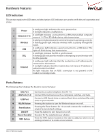
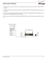
Hardware Features LED Indicators This section explains the LED states and descriptions. LED indicators are used to verify the unit's operation and status. 1 Power A solid green light indicates the unit is powered on. A red light indicates a malfunction. 2 Ethernet (1-4) A solid light indicates a connection to an Ethernet-enabled computer on ports 1-4. This LED blinks during data transmission. A solid green light indicates the wireless function is operating correctly. 3 Wireless A flashing green light indicates wireless traffic is passing through the router. 4 USB A solid green light indicates a good connection to a USB device. This light will blink during data transmission. A solid light indicates the DSL is synchronized. 5 DSL A flashing LED indicates the modem is attempting to synchronize with the DSL provider. A solid green light indicates that the modem has an IP address and is connected to the Internet. 6 Internet A red light indicates that the modem does not have an IP address or authentication has failed. No light indicates that an ADSL connection is not present or the modem is in bridge mode. Ports/Buttons The following chart displays the Router's connector types: 1 DSL Port Connect to an active telephone line (RJ-11). 2 LAN Ports (1-4) Connect Ethernet devices such as computers, switches, and hubs. 3 USB Port Connect a USB thumb drive or external hard drive and share files with users on your network. 4 WLAN Button Pressing this button to turn the Wireless feature on or off. 5 Reset Button Pressing the Reset button for 10 seconds restores the modem to its original factory default settings. 6 ON/OFF Press this button to turn the unit on or off. 7 Power Receptor Receptor for the supplied power adapter. 8 WPS Button Press the WPS button located on the side to add your device to an existing network or to create a new network. DSL-2750B User Guide 7
-
 1
1 -
 2
2 -
 3
3 -
 4
4 -
 5
5 -
 6
6 -
 7
7 -
 8
8 -
 9
9 -
 10
10 -
 11
11 -
 12
12 -
13
-
14
-
15
-
16
-
17
-
18
-
19
-
20
-
21
-
22
-
23
-
24
-
25
-
26
-
27
-
28
-
29
-
30
-
31
-
32
-
33
-
34
-
35
-
36
-
37
-
38
-
39
-
40
-
41
-
42
-
43
-
44
-
45
-
46
-
47
-
48
-
49
-
50
-
51
-
52
-
53
-
54
-
55
-
56
-
57
-
58
-
59
-
60
-
61
-
62
-
63
-
64
-
65
-
66
-
67
-
68
-
69
-
70
-
71
-
72
-
73
-
74
-
75
-
76
-
77
-
78
-
79
-
80
-
81
-
82
-
83
-
84
-
85
-
86
-
87
-
88
 |
 |
