D-Link DSN-5210-10 Hardware Reference Guide for DSN-5000-10
D-Link DSN-5210-10 - xStack Storage Area Network Array Hard Drive Manual
 |
UPC - 790069323980
View all D-Link DSN-5210-10 manuals
Add to My Manuals
Save this manual to your list of manuals |
D-Link DSN-5210-10 manual content summary:
- D-Link DSN-5210-10 | Hardware Reference Guide for DSN-5000-10 - Page 1
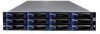
xStack Storage TM D-Link xStack Storage iSCSI SAN Array Managed SAN Solution DSN-5110-10, 5210-10, 5410-10 & 5000-10 Hardware Reference Guide Version 1.4 - D-Link DSN-5210-10 | Hardware Reference Guide for DSN-5000-10 - Page 2
City, California. UNIX® is a registered trademark of The Open Group. All other brand or product names are or may be trademarks or service marks, and are used to identify products or services, of their respective owners. D-Link Systems, Inc. 17595 Mount Herrmann Street Fountain Valley, CA 92708 ii - D-Link DSN-5210-10 | Hardware Reference Guide for DSN-5000-10 - Page 3
. However, should you need to replace it, consult your service documentation. Do not dispose of the battery along with household TYPE. DISPOSE OF USED BATTERIES ACCORDING TO THE INSTRUCTIONS. The iS512-10G product requires usage of laser Class A DSN-5000 series Hardware Reference Guide iii - D-Link DSN-5210-10 | Hardware Reference Guide for DSN-5000-10 - Page 4
require an export license from the United States government. Please contact D-Link Systems, Inc. for any export compliance questions. Document Revision Level 2009 Version 1.3: updated for 84 drive support and version 2.6.0 software May 2010 Version 1.4: added DSN-5110 and other minor updates iv - D-Link DSN-5210-10 | Hardware Reference Guide for DSN-5000-10 - Page 5
primary array and expansion array of the xStack Storage system from D-Link. This document assumes that users are computer literate, familiar with , the following documents are available from D-Link. xStack StorageSoftware User's Guide. This guide provides the information needed to configure and - D-Link DSN-5210-10 | Hardware Reference Guide for DSN-5000-10 - Page 6
to Friday 8:00am - 5:00pm PST/PDT D-Link Technical Support over the Internet: http://support.dlink.com Tech Support for customers within Canada: D-Link Technical Support over the Telephone Please see our support site for current number: http://support.dlink.ca Monday to Friday 7:30am to - D-Link DSN-5210-10 | Hardware Reference Guide for DSN-5000-10 - Page 7
3.5 Connecting to the iSCSI Data Ports 20 3.5.1 xStack Storage DSN-5110-10 & 5210-10 Data Ports 21 3.5.2 xStack Storage DSN-5410-10 Data Port 21 3.6 Connecting to the Management Port 21 3.7 Port 38 Appendix B Installing the System in a Rack 41 DSN-5000 series Hardware Reference Guide vii - D-Link DSN-5210-10 | Hardware Reference Guide for DSN-5000-10 - Page 8
This Page Left Intentionally Blank viii Contents - D-Link DSN-5210-10 | Hardware Reference Guide for DSN-5000-10 - Page 9
10 A 10/100/1000 Mbps Ethernet management port Two expansion connectors for attaching up to: Three additional expansion arrays for the DSN-5110-10; Six additional expansion arrays for the DSN-5210-10; Six additional expansion arrays for the DSN-5410-10 DSN-5000 series Hardware Reference Guide - D-Link DSN-5210-10 | Hardware Reference Guide for DSN-5000-10 - Page 10
for troubleshooting purposes Complete configuration and management of the storage system are available through the intuitive, graphical-based xStack Storage Management Center software. For the latest information about supported drives, consult the Interoperability Matrix found on the D-Link Support - D-Link DSN-5210-10 | Hardware Reference Guide for DSN-5000-10 - Page 11
-10 or DSN-5410-10 primary array Maximum number of SATA or SAS drives: 12 Each I/O module provides two SAS expansion ports Single or Dual I/O modules are allowed A DSN-500 I/O module can be installed in the empty bay of the DSN-5000-10 for High Availability DSN-5000 series Hardware Reference Guide - D-Link DSN-5210-10 | Hardware Reference Guide for DSN-5000-10 - Page 12
A system using a single controller (DSN-5110-10, DSN-5210-10 or DSN-5410-10) and its expansion array(s) may use SAS or SATA drives. A system using dual controllers for High Availability operation (DSN510 for the 5110-10, DSN-520 for the 5210-10 or DSN-540 for the 5410-10) requires SAS drives be used - D-Link DSN-5210-10 | Hardware Reference Guide for DSN-5000-10 - Page 13
drives for the DSN-5210-10 and DSN-5410-10 systems, or up to 48 drives for the DSN5110-10 system. Easy setup and configuration - can be installed anywhere on a Gigabit or 10-Gigabit Ethernet network data cache (48 hours with the 4GB data cache option). DSN-5000 series Hardware Reference Guide 5 - D-Link DSN-5210-10 | Hardware Reference Guide for DSN-5000-10 - Page 14
with a single I/O module is the DSN-5000-10. An additional I/O module for the DSN-5000-10 is the DSN-500), which is required when the DSN-5110-10, 5210-10 or 5410-10 system is equipped with dual controllers. To clarify: DSN-5110-10, DSN-5210-10 or DSN-5410-10 systems all have a single controller - D-Link DSN-5210-10 | Hardware Reference Guide for DSN-5000-10 - Page 15
in the DSN-5110-10, DSN-5210-10 or DSN-5410-10 to the second I/O module (DSN-500) installed in the DSN-5000-10 expansion array. You will now have dual redundancy between the DSN-5110-10, DSN-5210-10 or DSN-5410-10 and the DSN5000-10 expansion array. DSN-5000 series Hardware Reference Guide 7 - D-Link DSN-5210-10 | Hardware Reference Guide for DSN-5000-10 - Page 16
This Page Left Intentionally Blank 8 Chapter 1 Introduction - D-Link DSN-5210-10 | Hardware Reference Guide for DSN-5000-10 - Page 17
on the DSN-5000 series primary array (DSN5110-10, DSN-5210-10 & DSN-5410-10). The topics covered in this chapter are: Section 2.1, Front Panel Components Section 2.2, Rear Panel Components Section 2.3, Side, Top and Bottom Panel Components DSN-5000 series Hardware Reference Guide 9 - D-Link DSN-5210-10 | Hardware Reference Guide for DSN-5000-10 - Page 18
the right side of the front panel provide status information about the DSN-5000 series primary array enclosure. For a description of these LEDs, for Close-up View) Drive Slots Figure 2-1. Front View of the DSN-5000 series Primary Array Lever Release Button Enclosure LEDs Drive Status LEDs Figure - D-Link DSN-5210-10 | Hardware Reference Guide for DSN-5000-10 - Page 19
ON = normal operation. OFF = normal while DSN-5000 series primary array is booting. After initialization, this status indicates a problem with the DSN-5000 series primary array. Blink = used to will be illuminated, and the audible alarm will sound. DSN-5000 series Hardware Reference Guide 11 - D-Link DSN-5210-10 | Hardware Reference Guide for DSN-5000-10 - Page 20
. Each iSCSI data port has port speed and port activity LEDs (see Table 2-4 for the xStack Storage DSN-5110-10 and DSN-5210-10, and Table 2-5 for the xStack Storage DSN-5410-10). Management port (MGMT) - one 10/100/1000 RJ-45 management port is located to the right of the iSCSI data ports. The - D-Link DSN-5210-10 | Hardware Reference Guide for DSN-5000-10 - Page 21
& LED's 10G Data Port Primary Controller in Slot #0 Management Port Figure 2-7. Rear View of the DSN-5410-10 Primary Array with two controllers installed Two SAS Expansion Ports Figure 2-8. Close-up View of DSN-5410-10 Controller Rear Panel DSN-5000 series Hardware Reference Guide 13 - D-Link DSN-5210-10 | Hardware Reference Guide for DSN-5000-10 - Page 22
Port Activity Green Description ON = link is operating at 1 Gbps. OFF = link is operating at either 10 Mbps or 100 Mbps. ON = link is operational. Blink = data is being sent or received. Table 2-5. Port Speed and Port Activity LEDs (xStack Storage DSN-5410-10) LED Port Speed Color Yellow Port - D-Link DSN-5210-10 | Hardware Reference Guide for DSN-5000-10 - Page 23
LEDs (xStack Storage DSN-5110-10, 5210-10 and 5410-10) Switch / LED Ready/Fault "A" and "B" LEDs Color OFF Red Green OFF Green Yellow Description Primary array is powered off or performing its Power On Self Test. ON = a fault has occurred. Please contact D-Link Technical Support. ON = normal - D-Link DSN-5210-10 | Hardware Reference Guide for DSN-5000-10 - Page 24
This Page Left Intentionally Blank 16 Chapter 2 DSN-5000 Series Primary Array Layout - D-Link DSN-5210-10 | Hardware Reference Guide for DSN-5000-10 - Page 25
DSN-5000 series primary array (DSN-5110-10. DSN5210-10 & DSN-5410-10). The topics covered in this chapter are: Section 3.1, Site Considerations Section 3.2, Safety Considerations Section 3.3, Unpacking the DSN on the DSN-5000 series Primary Array DSN-5000 series Hardware Reference Guide 17 - D-Link DSN-5210-10 | Hardware Reference Guide for DSN-5000-10 - Page 26
mounted on a desktop or shelf. Observe the following considerations for desktop or shelf installations. Select a sturdy, level surface that can support the DSN-5000 series primary array. A fully populated unit weighs approximately 85 lbs. (38.6 kg.). Allow enough ventilation space between the - D-Link DSN-5210-10 | Hardware Reference Guide for DSN-5000-10 - Page 27
. Follow the instructions in the documentation for the rack. The operating ambient temperature of rack-mounted equipment must not exceed the maximum rated ambient temperature indicated in this guide. The rack cabinet must provide sufficient airflow to the front and back of the DSN-5000 series - D-Link DSN-5210-10 | Hardware Reference Guide for DSN-5000-10 - Page 28
sections describe how to connect the DSN-5000 series primary array data ports. If you have the DSN-5110-10 or 5210-10, follow the instructions in section 3.5.1. If you have the DSN-5410-10, follow the instructions in section 3.5.2. 20 Chapter 3 Installing the DSN-5000 Series Primary Array - D-Link DSN-5210-10 | Hardware Reference Guide for DSN-5000-10 - Page 29
-45 Ethernet cable (the DSN-5110-10 & 5210-10 primary arrays auto-sense the network link speed and type of cable DSN-5110-10 or DSN-5210-10 primary array port in sequence (port iSCSI 1, then port iSCSI 2, and so on). 3.5.2 xStack Storage DSN-5410-10 Data Port The DSN-5410-10 primary array has one 10 - D-Link DSN-5210-10 | Hardware Reference Guide for DSN-5000-10 - Page 30
(s). Data Port Connection Management Port Connection Figure 3-1. Connecting Data and Management Ports (DSN-5210-10 w/ Single Controller) Management Port Connection Data Port Connection Figure 3-2. Connecting Data and Management Ports (DSN-5410-10 with Single Controller) 22 Chapter 3 Installing the - D-Link DSN-5210-10 | Hardware Reference Guide for DSN-5000-10 - Page 31
Port Connections Figure 3-3. Connecting Data and Management Ports (DSN-5210-10 with Dual Controllers) To Host Servers Data Port Connections Management Port Connections Figure 3-4. Connecting Data and Management Ports (DSN-5410-10 with Dual Controllers) DSN-5000 series Hardware Reference Guide 23 - D-Link DSN-5210-10 | Hardware Reference Guide for DSN-5000-10 - Page 32
end of one power cord into one of the 3-pronged power connectors on the back of the DSN-5000 series primary array. Plug the other end of the power cord into a working AC outlet to the xStack Storage Management Center Software User's Guide. 24 Chapter 3 Installing the DSN-5000 Series Primary Array - D-Link DSN-5210-10 | Hardware Reference Guide for DSN-5000-10 - Page 33
-10 Expansion Arrays to a DSN-5210-10 or 5410-10 Primary Array Section 4.8, Connecting DSN-5000-10 Expansion Arrays to a DSN-5110-10 Primary Array Section 4.9, Connecting the AC Power Cords Section 4.10, Powering-on the DSN-5000-10 Expansion Array DSN-5000 series Hardware Reference Guide - D-Link DSN-5210-10 | Hardware Reference Guide for DSN-5000-10 - Page 34
, or controllers. OFF = normal operation. ON = normal operation. OFF = normal while DSN-5000-10 expansion array is booting. After initialization, this status indicates a problem with the DSN-5000-10 expansion array. Blink = DSN-5000-10 expansion array is trying to identify the physical location of - D-Link DSN-5210-10 | Hardware Reference Guide for DSN-5000-10 - Page 35
replaced (see Appendix A for information about installing or replacing drives) Green Flash = drive activity is occurring. Figure 4-3. Drive Numbers on the Primary and Expansion Arrays DSN-5000 series Hardware Reference Guide 27 - D-Link DSN-5210-10 | Hardware Reference Guide for DSN-5000-10 - Page 36
All site, safety, and rack-mount considerations listed for the DSN-5000 series primary array in Chapter 3 also apply to the DSN-5000-10 expansion array. 4.4 Unpacking the DSN-5000-10 Expansion Array After receiving the DSN-5000-10 expansion array, perform the following steps to ensure that it and - D-Link DSN-5210-10 | Hardware Reference Guide for DSN-5000-10 - Page 37
DSN-5000-10 expansion array. Returning the DSN-5000-10 the DSN-5000-10 expansion DSN-5000 series primary array and DSN-5000-10 DSN-5000-10 Expansion Array If the DSN-5000-10 DSN-5000-10 expansion array enclosure. Install DSN-5000-10 expansion array will be mounted in a rack, mount the DSN-5000-10 the DSN-5000-10 - D-Link DSN-5210-10 | Hardware Reference Guide for DSN-5000-10 - Page 38
DSN-5000-10 Expansion Arrays to a DSN-5210-10 or 5410-10 Primary Array To connect the first two DSN-5000-10 expansion arrays to a DSN DSN-5000-10 Expansion Array to the DSN on the DSN-5000 series DSN-5000 series primary array has a mini-SAS connector, and the DSN5000-10 the DSN-5000-10 expansion - D-Link DSN-5210-10 | Hardware Reference Guide for DSN-5000-10 - Page 39
chassis cable (mini-SAS to SAS) supplied with the DSN-5000-10 expansion array. When connecting the second through third expansion arrays, you must obtain a separate SAS-to-SAS cable for each I/O module (available separately at no cost from D-Link). DSN-5000 series Hardware Reference Guide 31 - D-Link DSN-5210-10 | Hardware Reference Guide for DSN-5000-10 - Page 40
expansion array. For best practices, use both power supplies and connect the second power receptacle to a different circuit. 4.10 Powering-on the DSN-5000-10 Expansion Array To power-on the DSN-5000-10 expansion array, turn on the rocker switches on both power supplies at the rear of the unit. When - D-Link DSN-5210-10 | Hardware Reference Guide for DSN-5000-10 - Page 41
replace or upgrade the Field Replaceable Units (FRUs) in the DSN-5000 series primary array and DSN-5000-10 expansion array. FRUs that can be replaced or upgraded include: Connection of the serial port for diagnostics when working with D-Link Support DSN-5000 series Hardware Reference Guide 33 - D-Link DSN-5210-10 | Hardware Reference Guide for DSN-5000-10 - Page 42
blank filler panels. For more information, see Figure 2-3 and Section 2.1. High Availability (HA) Note: A system using a single controller (DSN-5110-10. DSN-5210-10 or DSN-5410-10) and its expansion array(s) may use SAS or SATA drives. A system using dual controllers for High Availability operation - D-Link DSN-5210-10 | Hardware Reference Guide for DSN-5000-10 - Page 43
minutes. To replace a power supply and fan module: 1. Optionally, power down the DSN-5000 series primary array and remove the power cords from the back panel. 2. Squeeze the power cords and power on the DSN-5000 series primary array. Figure A-3. Removing a Power Supply and Fan Module (right-most - D-Link DSN-5210-10 | Hardware Reference Guide for DSN-5000-10 - Page 44
to replace a controller module on the primary array. 1. Power down the DSN-5000 series primary array and remove the power cords from the back panel. engage into place. 4. Replace the power cords and power on the DSN-5000 series primary array. Figure A-4. Removing the Controller Canister on the - D-Link DSN-5210-10 | Hardware Reference Guide for DSN-5000-10 - Page 45
expansion array. 1. Power down the DSN-5000 series primary and DSN-5000-10 expansion array and remove the power on either side of the I/O module on the DSN- 5000-10 expansion array and pull down to disengage the module, the DSN-5000 series primary array and DSN-500010 expansion array. Figure A-5. Removing - D-Link DSN-5210-10 | Hardware Reference Guide for DSN-5000-10 - Page 46
A.5 Connecting to the Diagnostic Serial Port The DSN-5000 series primary arrays have a 115.2 Kbps RS-232-C stereo mini-jack connector on the right side of the rear panel (see Figure A-5). Using this - D-Link DSN-5210-10 | Hardware Reference Guide for DSN-5000-10 - Page 47
4. Type the number that corresponds to the action you want to perform. 5. Follow the screen prompts to complete the activity. DSN-5000 series Hardware Reference Guide 39 - D-Link DSN-5210-10 | Hardware Reference Guide for DSN-5000-10 - Page 48
This Page Left Intentionally Blank 40 Appendix A Replacing and Upgrading FRUs - D-Link DSN-5210-10 | Hardware Reference Guide for DSN-5000-10 - Page 49
This appendix describes how to install the DSN-5000 series primary and DSN-5000-10 expansion arrays in a rack. The in the rack where you will be installing the rails that will support the primary array and any expansion arrays (if appropriate). When DSN-5000 series Hardware Reference Guide 41 - D-Link DSN-5210-10 | Hardware Reference Guide for DSN-5000-10 - Page 50
the exact length to match the distance between the front and rear vertical supports of the rack. 3. After determining which rear rails to use, orient Insert the rails into the rack and secure the rails to the vertical supports using one of the following methods: If the rack has square punchout - D-Link DSN-5210-10 | Hardware Reference Guide for DSN-5000-10 - Page 51
the rack. 10. Carefully slide the array onto the rails, pushing it back until the flanges on the front of the chassis meet the vertical supports. Figure array and tighten the screw to secure the array to the vertical supports, as shown in the following figure. Repeat this step using another screw - D-Link DSN-5210-10 | Hardware Reference Guide for DSN-5000-10 - Page 52
Figure B-5. Securing the Array to the Rack Secure to the vertical supports 44 Appendix B Installing the System in a Rack
-
 1
1 -
 2
2 -
 3
3 -
 4
4 -
 5
5 -
 6
6 -
 7
7 -
8
-
9
-
10
-
11
-
12
-
13
-
14
-
15
-
16
-
17
-
18
-
19
-
20
-
21
-
22
-
23
-
24
-
25
-
26
-
27
-
28
-
29
-
30
-
31
-
32
-
33
-
34
-
35
-
36
-
37
-
38
-
39
-
40
-
41
-
42
-
43
-
44
-
45
-
46
-
47
-
48
-
49
-
50
-
51
-
52
 |
 |
xStack Storage
TM
D-Link xStack Storage iSCSI SAN Array
Managed SAN Solution
DSN-5110-10, 5210-10, 5410-10 & 5000-10
Hardware Reference Guide
Version 1.4