D-Link DSN-6120 User Manual
D-Link DSN-6120 Manual
 |
View all D-Link DSN-6120 manuals
Add to My Manuals
Save this manual to your list of manuals |
D-Link DSN-6120 manual content summary:
- D-Link DSN-6120 | User Manual - Page 1
D-Link iSCSI IP SAN storage GbE iSCSI to SATA II / SAS RAID IP SAN storage DSN-6110 & DSN-6120 User Manual Version 1.0 1 - D-Link DSN-6120 | User Manual - Page 2
in DSN-6110. Caution Do not attempt to service, change, disassemble or upgrade the equipment's components by yourself. Doing so may violate your warranty and expose you to electric shock. Refer all servicing to authorized service personnel. Please always follow the instructions in this user's manual - D-Link DSN-6120 | User Manual - Page 3
Table of Contents Chapter 1 Overview 6 1.1 Features 6 1.1.1 Highlights ...7 1.2 RAID concepts 8 1.2.1 Terminology ...8 1.2.2 RAID levels...10 1.2.3 Volume relationship 11 1.3 iSCSI concepts 11 1.4 IP SAN storage specifications 13 1.4.1 Technical specifications 13 1.4.2 FCC - D-Link DSN-6120 | User Manual - Page 4
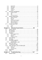
5.7.2 Upgrade firmware of JBOD 97 5.8 MPIO and MC/S 98 5.9 Trunking and LACP 100 5.10 Dual controllers (only for DSN-6120 101 5.10.1 5.10.2 Perform I/O...101 Ownership ...102 5.10.3 Controller status 103 5.11 Replication 104 5.12 VLAN 114 Chapter 6 Troubleshooting 117 6.1 System - D-Link DSN-6120 | User Manual - Page 5
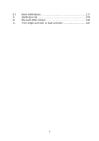
6.2 Event notifications 117 A. Certification list 123 B. Microsoft iSCSI initiator 126 C. From single controller to Dual controller 132 5 - D-Link DSN-6120 | User Manual - Page 6
Link DSN-6000 series IP SAN storage provides non-stop service with a high degree of fault tolerance by using D-Link RAID technology and advanced array management features. DSN-6110/6120 can be taken manually or by schedule every hour or every day, depends on the modification. D-Link IP SAN storage - D-Link DSN-6120 | User Manual - Page 7
Link DSN-6110/6120 feature highlights Host Interface 8 x iSCSI GbE ports (DSN-6120) 4 x iSCSI GbE ports (DSN-6110) Drive Interface 12 x SAS or SATA II RAID Controllers Single controller, can be upgradable to dual (DSN-6110) Dual-active RAID controllers (DSN-6120 and failover support on the - D-Link DSN-6120 | User Manual - Page 8
1.2 RAID concepts RAID is the abbreviation of "Redundant Array of Independent Disks". The basic idea of RAID is to combine multiple drives together to form one large logical drive. This RAID drive obtains performance, capacity and reliability than a single drive. The operating system detects the - D-Link DSN-6120 | User Manual - Page 9
virtual disks. Small Computer Systems Interface. Serial Attached SCSI. Self-Monitoring Analysis and Reporting Technology. World Wide Name. Host Bus Adapter. SCSI Enclosure Services. Network Interface Card. Battery Backup Module Part 2: iSCSI iSCSI LACP Internet Small Computer Systems Interface - D-Link DSN-6120 | User Manual - Page 10
an iSCSI storage system over the iSCSI data ports. Internet Storage Name Service. Part 3: Dual controller SBB Storage Bridge Bay. The objective of enclosure management requirements for an enclosure controller slot that will support a variety of storage controllers from a variety of independent - D-Link DSN-6120 | User Manual - Page 11
concepts iSCSI (Internet SCSI) is a protocol which encapsulates SCSI (Small Computer System Interface) commands and data in TCP/IP packets for linking storage devices with servers over common IP infrastructures. iSCSI provides high performance SANs over standard IP networks like LAN, WAN or the - D-Link DSN-6120 | User Manual - Page 12
(s) use their own iSCSI and TCP/IP stacks on board. Hardware iSCSI HBA(s) provide its own initiator tool. Please refer to the vendors' HBA user manual. Microsoft, Linux, Solaris and Mac provide iSCSI initiator driver. Please contact DLink for the latest certification list. Below are the available - D-Link DSN-6120 | User Manual - Page 13
port seamless take-over (only for DSN-6120) The management port can be transferred smoothly to the other controller with the same IP address 6. Online firmware upgrade, no system down time (only for DSN-6120) 7. Multiple target iSCSI nodes per controller support Each LUN can be attached to - D-Link DSN-6120 | User Manual - Page 14
1. D-Link writeable snapshot Built-in snapshot with rollback enabled Snapshot enabled up to 16 volumes, each logical volume supports up to 32 snapshot volumes, total 512 snapshot volumes per system 2. Microsoft Windows Volume Shadow Copy Services (VSS) - D-Link DSN-6120 | User Manual - Page 15
enabled 4. Load-balancing and failover through MPIO, MC/S, Trunking, and LACP 5. Up to 32 multiple nodes support 6. VLAN support Host connection 1. 4x GbE ports (DSN-6110)/ 8 x GbE ports (DSN-6120) 2. Host access control: Read-Write and Read-Only 3. Up to 128 sessions 4. One logic volume can - D-Link DSN-6120 | User Manual - Page 16
compliant 4. Multiple IO transaction processing 5. Tagged command queuing 6. Disk auto spin-down support 7. S.M.A.R.T. for SATA II drives 8. SAS JBODs expansion Power and Environment ) Rack Mount Instructions - The following or similar rack-mount instructions are included with the installation - D-Link DSN-6120 | User Manual - Page 17
This equipment intended for installation in restricted access location. Access can only be gained by SERVICE PERSONS or by USERS who have been instructed about the reasons for the restrictions applied to the location and about any precautions that shall be taken. Access is through the use - D-Link DSN-6120 | User Manual - Page 18
switches with LCAP / Trunking (optional). 6. CHAP security information, including CHAP username and secret (optional). 2.3 Enclosure 2.3.1 Front view Drive slot numbering Slot 1 Slot 2 Slot 3 Figure 2.3.1.1 (DSN-6110/6120) Slot 4 Slot 5 Slot 6 Slot 7 Slot 8 Slot 9 18 Slot 10 Slot 11 Slot 12 - D-Link DSN-6120 | User Manual - Page 19
The drives can be installed into any slot in the enclosure. Slot numbering will be reflected in web UI. Tips It is advisable to install at least one drive in slots 1 ~ 4. System event logs are saved to drives in these slots; If no drives are fitted the event logs will be lost in the event of a - D-Link DSN-6120 | User Manual - Page 20
populated with drives. To install SAS or SATA drives with no Bridge Board use the front mounting holes: To install SATA drives with Bridge Board (DSN-654), fit the Bridge Board first Then install the drive using the rear mounting holes: 20 - D-Link DSN-6120 | User Manual - Page 21
. Off No HDD. HDD access LED: Blue blinking HDD is accessing. Off No HDD. HDD tray handhold. Latch for tray kit removal. 2.3.4 Rear view Figure 2.3.4.1 (DSN-6120) PSU and Fan module description: Controller 2. 21 - D-Link DSN-6120 | User Manual - Page 22
Power supply unit (PSU2). Fan module (FAN3 / FAN4). Power supply unit (PSU1). Fan module (FAN1 / FAN2). Figure 2.3.4.2 (DSN-6110) PSU and Fan module description: Controller. Power supply unit (PSU2). Fan module (FAN3 / FAN4). Power supply unit (PSU1 - D-Link DSN-6120 | User Manual - Page 23
) Controller Health LED: Green Controller status normal or in the booting. Red Other than above status. Master Slave LED: (only for DSN-6120) Green Master controller. Off Slave controller. Dirty Cache LED: Orange Data on the cache waiting for flush to disks. Off No - D-Link DSN-6120 | User Manual - Page 24
1. Shutdown IP SAN storage, then power off. 2. Remove the cover of battery backup module. 3. Insert the battery backup module. 4. Tighten the screws up. 5. Power on, BBM will work. Figure 2.4.1 Figure 2.4.2 24 - D-Link DSN-6120 | User Manual - Page 25
2.5 Deployment Please refer to the following topology and have all the connections ready. Figure 2.5.1 (DSN-6120) Figure 2.5.2 (DSN-6110) 1. Setup the hardware connection before power on servers. Connect console cable, management port cable, and iSCSI data port cables in advance. 2. In addition, - D-Link DSN-6120 | User Manual - Page 26
the target twice (both controller 1 and controller 2), and then MPIO should be setup automatically. (only for DSN-6120) Tips iSNS server is recommended for dual controller system. For better data service availability, all the connections among host servers, GbE switches, and the dual controllers are - D-Link DSN-6120 | User Manual - Page 27
: http://www.ssh.com/ PuTTY: http://www.chiark.greenend.org.uk/ Host name: 192.168.0.32 (Default IP) Login name: admin Default password: 123456 Tips D-Link product supports SSH for remote control only. For using SSH, the IP address and password are required for login. 3.1.3 Web UI - D-Link DSN-6120 | User Manual - Page 28
Figure 3.1.4.1 User name: admin Default password: 123456 After login, choose the functions which lists on the left side of window to make any configuration. Figure 3.1.4.2 There are seven indicators and three icons at the top-right corner. Figure 3.1.4.3 Indicator description: RAID light: Green - D-Link DSN-6120 | User Manual - Page 29
Temperature light: Green Temperature is normal. Red Temperature is abnormal. Voltage light: Green voltage is normal. Red voltage is abnormal. UPS light: Green UPS works well. Red UPS fails. Fan light: Green Fan works well. Red Fan fails. Power light: Green Power - D-Link DSN-6120 | User Manual - Page 30
3.2 How to use the system quickly The following methods will describe the quick guide to use this IP SAN storage. 3.2.1 Quick installation Please make sure that there are some free drives installed in this system. SAS drives are recommended. - D-Link DSN-6120 | User Manual - Page 31
Step2: Confirm the management port IP address and DNS, and then click "Next". Figure 3.2.1.3 Step 3: Set up the data port IP and click "Next". Figure 3.2.1.4 Step 4: Set up the RAID level and volume size and click "Next". 31 - D-Link DSN-6120 | User Manual - Page 32
Figure 3.2.1.5 Step 5: Check all items, and click "Finish". Figure 3.2.1.6 3.2.2 Volume creation wizard "Volume create wizard" has a smarter policy. When the system is inserted with some HDDs. "Volume create wizard" lists all possibilities and sizes in different RAID levels, it will use all - D-Link DSN-6120 | User Manual - Page 33
different sizes of HDDs, e.g., 8*200G and 8*80G, it lists all possibilities and combination in different RAID level and different sizes. After user chooses RAID level, user may find that some HDDs are available (free status). The result is using smarter policy designed by DLink. It gives user: 1. - D-Link DSN-6120 | User Manual - Page 34
Figure 3.2.2.2 Step 3: Decide VD size. User can enter a number less or equal to the default number. Then click "Next". Figure 3.2.2.3 Step 4: Confirmation page. Click "Finish" if all setups are correct. Then a VD will be created. Step 5: Done. The system is available now. Figure 3.2.2.4 (Figure - D-Link DSN-6120 | User Manual - Page 35
of web GUI. System configuration System setting System name / Date and time / System indication Network settin MAC address / Address / DNS / Port g Login setting Login configuration / Admin password / User password Mail setting Mail Notification SNMP / Messenger / System log server - D-Link DSN-6120 | User Manual - Page 36
Upgrade Browse the firmware to upgrade Firmware synch Synchronize the slave controller's firmware version with the ronization master's Reset to factory Sure to reset to factory default? default Import and Import/Export / Import file export Reboot and shu - D-Link DSN-6120 | User Manual - Page 37
Check "Change date and time" to set up the current date, time, and time zone before using or synchronize time from NTP (Network Time Protocol) server. Click "Confirm" in System indication to turn on the system indication LED. Click again to turn off. 4.2.2 Network setting "Network setting" is for - D-Link DSN-6120 | User Manual - Page 38
levels of event logs are needed to be sent via Mail. Default setting only enables ERROR and WARNING event logs. Please also make sure the DNS server IP is well-setup so the event notification mails can be sent successfully. 38 - D-Link DSN-6120 | User Manual - Page 39
Figure 4.2.4.1 4.2.5 Notification setting "Notification setting" can set up SNMP trap for alerting via SNMP, pop-up message via Windows messenger (not MSN), alert via syslog protocol, and event log filter for web UI. 39 - D-Link DSN-6120 | User Manual - Page 40
necessary, click "Download" to get MIB file and import to SNMP. To use "Messenger", user must enable the service "Messenger" in Windows (Start Control Panel Administrative Tools Services Messenger), and then event logs can be received. It allows up to 3 messenger addresses. User can choose - D-Link DSN-6120 | User Manual - Page 41
data ports. DSN-6110/6120 has four gigabit ports on each controller to transmit data. Each of them must be assigned to an IP address and be set up in multi-homed mode, or the link aggregation / trunking mode has been set up. When there are multiple data ports setting up in link - D-Link DSN-6120 | User Manual - Page 42
description of multi-homed / trunking / LACP functions. 1. Multi-homed: Default mode. Each of iSCSI data port is connected by itself and is not link aggregation and trunking. This function is also for Multipath functions. Select this mode can also remove the setting of Trunking / LACP in same time - D-Link DSN-6120 | User Manual - Page 43
iSCSI data ports on each controller, select at least two NICs for link aggregation.) Figure 4.3.1.4 For example, LAN1 and LAN2 are set as Trunking Trunking / LACP setting, check the gray button of LAN port, click "Delete link aggregation". Then it will pop up a message to confirm. Ping host: - D-Link DSN-6120 | User Manual - Page 44
an iSNS server IP address into iSNS server lists in order that iSCSI initiator service can send queries. The entity name can be changed. Figure 4.3.2.1 4.3.3 Node "Node" can view the target name for iSCSI initiator. DSN-6110/6120 supports up to 32 multi-nodes. There are 32 default nodes created for - D-Link DSN-6120 | User Manual - Page 45
Figure 4.3.3.1 CHAP: CHAP is the abbreviation of Challenge Handshake Authentication Protocol. CHAP is a strong authentication method used in point-to-point for user login. It's a type of authentication in which the authentication server sends the client a key to be used for encrypting the username - D-Link DSN-6120 | User Manual - Page 46
Figure 4.3.3.3 5. Go to "/ iSCSI configuration / CHAP account" page to create CHAP account. Please refer to next section for more detail. 6. Check the gray button of "OP." column, click "User". 7. Select CHAP user(s) which will be used. It's a multi option; it can be one or more. If choosing none, - D-Link DSN-6120 | User Manual - Page 47
Rename alias: User can create an alias to one device node. 1. Check the gray button of "OP." column next to one device node. 2. Select "Rename alias". 3. Create an alias for that device node. 4. Click "OK" to confirm. 5. An alias appears at the end of that device node. Figure 4.3.3.6 Figure - D-Link DSN-6120 | User Manual - Page 48
all connection(s) of the session. Figure 4.3.4.2 (iSCSI Connection) 4.3.5 CHAP account "CHAP account" can manage a CHAP account for authentication. DSN-6110/6120 can create multiple CHAP accounts. To setup CHAP account, please follow the procedures. 1. Click "Create". 2. Enter "User", "Secret", and - D-Link DSN-6120 | User Manual - Page 49
selected. For example, set PD slot number 4 to dedicated spare disk. Step 1: Check to the gray button of PD 4, select "Set Dedicated spare", it will link to next page. 49 - D-Link DSN-6120 | User Manual - Page 50
Figure 4.4.1.1 Step 2: If there is any RG which is in protected RAID level and can be set with dedicate spare disk, select one RG, and then click "Submit". Figure 4.4.1.2 Step 3: Done. View "Physical disk" page. Figure 4.4.1.3 (Figure 4.4.1.3: Physical disks in slot 1,2,3 are created for a RG named - D-Link DSN-6120 | User Manual - Page 51
Figure 4.4.1.4 PD column description: Slot Size (GB) (MB) RG Name Status Health Usage The position of a hard drive. The button next to the number of slot shows the functions which can be executed. Capacity of hard drive. The unit can be displayed in GB or MB. RAID group name. The status of - D-Link DSN-6120 | User Manual - Page 52
hard drive to global spare of all RGs. Set Dedicated spares Set a hard drive to dedicated spare of the selected RG. Upgrade Upgrade hard drive firmware. Disk Scrub Scrub the hard drive. Turn on/off Turn on the indication LED of the hard drive. Click again to turn 52 - D-Link DSN-6120 | User Manual - Page 53
the off. indication LED More Show hard drive detail information. information 4.4.2 RAID group "RAID group" can view the status of each RAID group, create, and modify RAID groups. The following is an example to create a RG. Step 1: Click "Create", enter "Name", choose "RAID level", click " - D-Link DSN-6120 | User Manual - Page 54
Figure 4.4.2.2 (Figure 4.4.2.2: There is a RAID 0 with 4 physical disks, named "RG-R0". The second RAID group is a RAID 5 with 3 physical disks, named "RG-R5".) Step 3: Done. View "RAID group" page. RG column description: Name Total (GB) (MB) Free (GB) (MB) #PD #VD Status Health The button - D-Link DSN-6120 | User Manual - Page 55
disk roaming; it can be executed when RG status is online. This is for online disk roaming purpose. Regenerate parity for the RAID group. It supports RAID 3 / 5 / 6 / 30 / 50 / 60. Delete the RAID group. Set the RG ownership to the other controller. Change the disk property of write cache and - D-Link DSN-6120 | User Manual - Page 56
More information Command queuing: "Enabled" Enable disk command queue. (Default) "Disabled" Disable disk command queue. Show RAID group detail information. 4.4.3 Virtual disk "Virtual disk" can view the status of each Virtual disk, create, and modify virtual disks. The following is an example - D-Link DSN-6120 | User Manual - Page 57
Step 2: Confirm page. Click "OK" if all setups are correct. Figure 4.4.3.2 (Figure 4.4.3.2: Create a VD named "VD-01", from "RG-R0".) Step 3: Done. View "Virtual disk" page. VD column description: Name Size (GB) (MB) Write Priority Bg rate The button includes the functions which can be - D-Link DSN-6120 | User Manual - Page 58
Status Type Clone Schedule Health R % RAID #LUN Snapshot (GB) (MB) number the background priority of a VD is, the more background I/O will be scheduled to execute. The status of virtual disk: "Online" The virtual disk is online. "Offline" The virtual disk is offline. "Initiating" The - D-Link DSN-6120 | User Manual - Page 59
: Create Create a virtual disk. Extend Extend the virtual disk capacity. Parity check Execute parity check for the virtual disk. It supports RAID 3 / 5 / 6 / 30 / 50 / 60. Regenerate parity: "Yes" Regenerate RAID parity and write. "No" Execute parity check only and find mismatches - D-Link DSN-6120 | User Manual - Page 60
Attach LUN editing. "Disabled" Disable AV-media mode. (Default) Type: "RAID" the virtual disk is normal. (Default) "Backup" the virtual disk is for clone usage. Attach to a LUN. Detach LUN Detach to a LUN. List LUN List attached LUN(s). Set clone Set the target virtual disk for - D-Link DSN-6120 | User Manual - Page 61
space is 15GB, and used 1GB for saving snapshot index.) Step 3: Take a snapshot. In "/ Volume configuration / Snapshot", click "Take snapshot". It will link to next page. Enter a snapshot name. Figure 4.4.4.3 Step 4: Expose the snapshot VD. Check to the gray button next to the Snapshot VD number - D-Link DSN-6120 | User Manual - Page 62
Figure 4.4.4.4 Figure 4.4.4.5 (Figure 4.4.4.5: This is the snapshot list of "VD-01". There are two snapshots. Snapshot VD "SnapVD-01" is exposed as read-only, "SnapVD-02" is exposed as read-write.) Step 5: Attach a LUN to a snapshot VD. Please refer to the next section for attaching a LUN. Step 6: - D-Link DSN-6120 | User Manual - Page 63
"Good" The snapshot is good. "Failed" The snapshot fails. Exposure Snapshot VD is exposed or not. Right The right of snapshot: "Read-write" The snapshot VD can be read / write. "Read-only" The snapshot VD is read only. #LUN Number of LUN(s) that snapshot VD is attached. - D-Link DSN-6120 | User Manual - Page 64
Figure 4.4.5.1 Figure 4.4.5.2 LUN operation description: Attach Detach Attach a logical unit number to a virtual disk. Detach a logical unit number from a virtual disk. The matching rules of access control are followed from the LUN' created time; the earlier created LUN is prior to the - D-Link DSN-6120 | User Manual - Page 65
4.4.6 Example The following is an example to create volumes. This example is to create two VDs and set a global spare disk. Example This example is to create two VDs in one RG, each VD shares the cache volume. The cache volume is created after system boots up automatically. Then set a global spare - D-Link DSN-6120 | User Manual - Page 66
Step 2: Create VD (Virtual Disk). To create a data user volume, please follow the procedures. Figure 4.4.6.3 1. Select "/ Volume configuration / Virtual disk". 2. Click "Create". 3. Input a VD name, choose a RG Name and enter a size for this VD; decide the stripe height, block size, read / write - D-Link DSN-6120 | User Manual - Page 67
2. In "/ Volume configuration / Logical unit", click "Attach". The procedures are as follows: Figure 4.4.6.5 1. Select a VD. 2. Input "Host" IQN, which is an iSCSI node name for access control, or fill-in wildcard "*", which means every host can access to this volume. Choose LUN and permission, and - D-Link DSN-6120 | User Manual - Page 68
Figure 4.4.6.7 (Figure 4.4.6.7: Slot 4 is set as a global spare disk.) Step 5: Done. Delete VDs, RG, please follow the below steps. Step 6: Detach a LUN from the VD. In "/ Volume configuration / Logical unit", Figure 4.4.6.8 1. Check the gray button next to the LUN; click "Detach". There will pop up - D-Link DSN-6120 | User Manual - Page 69
Step 8: Delete a RG (RAID group). To delete a RAID group, please follow the procedures: 1. Select "/ Volume configuration / RAID group". 2. Select a RG which all its VD are deleted, otherwise the this RG cannot be deleted. 3. Check the gray button next to the RG number click "Delete". 4. There will - D-Link DSN-6120 | User Manual - Page 70
4.5.1 Hardware monitor "Hardware monitor" can view the information of current voltages and temperatures. 70 - D-Link DSN-6120 | User Manual - Page 71
trigger auto shutdown. 4.5.2 UPS "UPS" can set up UPS (Uninterruptible Power Supply). Figure 4.5.2.1 (Figure 4.5.2.1: Without UPS.) Currently, the system only supports and communicates with smart-UPS of APC (American Power Conversion Corp.) UPS. Please review the details from the website: http://www - D-Link DSN-6120 | User Manual - Page 72
First, connect the system and APC UPS via RS-232 for communication. Then set up the shutdown values (shutdown battery level %) when power is failed. UPS in other companies can work well, but they have no such communication feature with the system. (Figure 4.5.2.2: With Smart-UPS.) Figure 4.5.2.2 - D-Link DSN-6120 | User Manual - Page 73
in progress" "Batteries failed. Please change them NOW!" Current power percentage of battery level. 4.5.3 SES SES represents SCSI Enclosure Services, one of the enclosure management standards. "SES configuration" can enable or disable the management of SES. Figure 4.5.3.1 (Figure 4.5.1.1: Enable - D-Link DSN-6120 | User Manual - Page 74
S.M.A.R.T. only supports SATA drives. SAS drives do not have this function now. It will show N/A in system event logs to record critical events, "Upgrade" to the latest firmware, "Firmware synchronization" to synchronized firmware versions on both controllers, "Reset to factory default" to reset all - D-Link DSN-6120 | User Manual - Page 75
Status description: Normal Degraded Lockdown Single Dual controllers are in normal stage. One controller fails or has been plugged out. The firmware of two controllers is different or the size of memory of two controllers is different. Single controller mode. 4.6.2 Event log "Event log" can - D-Link DSN-6120 | User Manual - Page 76
Figure 4.6.2.1 The event log is displayed in reverse order which means the latest event log is on the first / top page. The event logs are actually saved in the first four hard drives; each hard drive has one copy of event log. For one system, there are four copies of event logs to make sure users - D-Link DSN-6120 | User Manual - Page 77
upgrading, the system must reboot manually to make the new firmware took effect. 4.6.4 Firmware synchronization "Firmware synchronization" can synchronize the firmware version when controller 1 and controller 2's firmware are different. It will upgrade the firmware of slave controller to master - D-Link DSN-6120 | User Manual - Page 78
4.6.5 Reset to factory default "Reset to factory default" allows user to reset IP SAN storage to factory default setting. Figure 4.6.5.1 Reset to default value, the password is: 1234, and IP address to default 192.168.0.32 4.6.6 Import and export "Import and export" allows user to save system - D-Link DSN-6120 | User Manual - Page 79
4.6.7 Reboot and shutdown "Reboot and shutdown" can "Reboot" and "Shutdown" the system. Before power off, it's better to execute "Shutdown" to flush the data from cache to physical disks. The step is necessary for data protection. Figure 4.6.7.1 4.7 Home/Logout/Mute In the right-upper corner of web - D-Link DSN-6120 | User Manual - Page 80
spare disk to rebuild the degraded RG to a complete one. It will detect dedicated spare disk as rebuild disk first, then global spare disk. D-LINK IP SAN storage supports Auto-Rebuild. Take RAID 6 for example: 1. When there is no global spare disk or dedicated spare disk in the system, The RG will - D-Link DSN-6120 | User Manual - Page 81
Rebuild operation description: RAID 0 RAID 1 N-way mirror RAID 3 RAID 5 RAID 6 RAID 0+1 RAID 10 RAID 30 RAID 50 RAID 60 JBOD Disk striping. No protection for data. RG fails if any hard drive fails or unplugs. Disk mirroring over 2 disks. RAID 1 allows one hard drive fails or unplugging. Need one - D-Link DSN-6120 | User Manual - Page 82
5". There will be a pup- up which indicates that HDD is not enough to support the new setting of RAID level, click "Select PD" to increase hard drives, . If there is no problem, click "OK". 5. Finally a confirmation page shows the detail of RAID information. If there is no problem, click "OK" to - D-Link DSN-6120 | User Manual - Page 83
To do migration, the total size of RG must be larger or equal to the original RG. It does not allow expanding the same RAID level with the same hard disks of original RG. The below operations are not allowed when a RG is being migrated. System would reject these operations: 1. Add dedicated spare. - D-Link DSN-6120 | User Manual - Page 84
Figure 5.3.2 Tips The size of VD extension must be larger than original. Caution VD Extension cannot be executed during rebuilding or migration. 5.4 Snapshot Snapshot-on-the-box captures the instant state of data in the target volume in a logical sense. The underlying logic is Copy-on-Write -- - D-Link DSN-6120 | User Manual - Page 85
5.4.1 Create snapshot volume To take a snapshot of the data, please follow the procedures. 1. Select "/ Volume configuration / Virtual disk". 2. Check the gray button next to the VD number; click "Set snapshot space". 3. Set up the size for snapshot. The minimum size is suggested to be 20% of VD - D-Link DSN-6120 | User Manual - Page 86
", click "Cleanup". 2. "Cleanup snapshot" will delete all snapshots of the VD and release snapshot space. 5.4.2 Auto snapshot The snapshot copies can be taken manually or by schedule such as hourly or daily. Please follow the procedures. 1. There are two methods to set auto snapshot. In "/ Volume - D-Link DSN-6120 | User Manual - Page 87
up message when user executes rollback function. 5.4.4 Snapshot constraint D-LINK snapshot function applies Copy-on-Write technique on UDV/VD and Then the snapshot may have an incomplete image of original data. The problem does not belong to the storage device. To avoid this data inconsistent issue - D-Link DSN-6120 | User Manual - Page 88
Besides the sync tool, Microsoft develops VSS (volume shadow copy service) to prevent this issue. VSS is a mechanism for creating consistent problem of datainconsistent. For more detail about the VSS, please refer to http://technet.microsoft.com/en-us/library/cc785914.aspx. DSN-6110/6120 can support - D-Link DSN-6120 | User Manual - Page 89
one (the first snapshot) and so on. 2. If the snapshot is taken manually, when taking the 33rd snapshot will fail and a warning message will be showed Check the firmware version of two systems first. It is better that either systems have the same firmware version or system-2 firmware version is - D-Link DSN-6120 | User Manual - Page 90
5.6 VD clone The user can use VD clone function to backup data from source VD to target VD, set up backup schedule, and deploy the clone rules. The procedures of VD clone are on the following: 1. Copy all data from source VD to target VD at the beginning (full copy). 2. Use Snapshot technology to - D-Link DSN-6120 | User Manual - Page 91
3. Here are the objects, a Source VD and a Target VD. Before starting clone process, it needs to deploy the VD Clone rule first. Click "Configuration". Figure 5.6.3 4. There are three clone configurations, describe on the following. Snapshot space: Figure 5.6.4 Figure 5.6.4 This setting is the - D-Link DSN-6120 | User Manual - Page 92
Figure 5.6.5 The threshold setting will monitor the usage amount of snapshot space. When the used snapshot space achieves its threshold, system will automatically take a clone snapshot and start VD clone process. The purpose of threshold could prevent the incremental copy fail immediately when - D-Link DSN-6120 | User Manual - Page 93
Figure 5.6.7 6. Select the target VD. Then click "Confirm". Figure 5.6.8 7. Now, the clone target "TargetVD_R6" has been set. Figure 5.6.9 8. Click "Start clone", the clone process will start. 93 - D-Link DSN-6120 | User Manual - Page 94
Figure 5.6.10 9. The default setting will create a snapshot space automatically which the capacity is double size of the VD space. Before starting clone, system will initiate the snapshot space. Figure 5.6.11 10. After initiating the snapshot space, it will start cloning. Figure 5.6.12 11. Click " - D-Link DSN-6120 | User Manual - Page 95
Figure 5.6.13 12. There are "Set Clone schedule" and "Clear Clone schedule" in this page. Please remember that "Threshold" and "Restart the task an hour later if failed" options in VD configuration will take effect after clone schedule has been set. Figure 5.6.14 Run out of snapshot space while VD - D-Link DSN-6120 | User Manual - Page 96
the clone process. Each time the clone snapshot failed, it means that the system loses the reference value of incremental data. So it will start a full copy at next clone process. When running out of snapshot space, the flow diagram of VD clone procedure will be like the following. Figure 5.6.15 96 - D-Link DSN-6120 | User Manual - Page 97
5.7 SAS JBOD expansion 5.7.1 Connecting JBOD D-LINK DSN-6000 series support up to 4 additional SAS/SATA JBODs for capacity cascaded. RAID Storage System DSN-6020 no. Max HDD no. Dual controllers + Dual JBOD DSN-6120 4 60 5.7.2 Upgrade firmware of JBOD To upgrade the firmware of JBOD, please follow - D-Link DSN-6120 | User Manual - Page 98
in local hard drive, then click "Browse" to select the file. Click "Confirm". 4 After finished upgrading, the system must reboot manually to make the new firmware took effect. 5.8 MPIO and MC/S These features come from iSCSI initiator. They can be setup from iSCSI initiator to establish redundant - D-Link DSN-6120 | User Manual - Page 99
2. MC/S: MC/S (Multiple Connections per Session) is a feature of iSCSI protocol, which allows combining several connections inside a single session for performance and failover purposes. In this way, I/O can be sent on any TCP/IP connection to the target. If one connection fails, another connection - D-Link DSN-6120 | User Manual - Page 100
supported Windows Server editions only. 4. MC/S can provide higher throughput than MPIO in Windows system, but it consumes more CPU resources than MPIO. 5.9 Trunking and LACP Link , LACP port can be defined as active or passive. D-LINK IP SAN Storage implements it as active mode which means that - D-Link DSN-6120 | User Manual - Page 101
switch. Figure 5.9.2 Caution Before using trunking or LACP, the gigabit switch must support trunking or LACP and enabled. Otherwise, host can not connect the link with storage device. 5.10 Dual controllers (only for DSN-6120) 5.10.1 Perform I/O Please refer to the following topology and have all the - D-Link DSN-6120 | User Manual - Page 102
Figure 5.10.1.1 5.10.2 Ownership When creating RG, it will be assigned with a prefered owner, the default owner is controller 1. To change the RG ownership, please follow the procedures. 1 Select "/ Volume configuration / RAID group". 2 Check the gray button next to the RG name; click "Set preferred - D-Link DSN-6120 | User Manual - Page 103
controller 1 is fixed or replaced, The current owner of all RGs will be asigned back to their prefered owner. 3. Lockdown: Dual controller mode. The firmware of two controllers is different or the size of memory of two controllers is different. In this stage, only master controller can work and - D-Link DSN-6120 | User Manual - Page 104
source IP SAN storage The Replication uses the last iSCSI port on the controller to replicate the data. That is the forth iSCSI port on DSN-6110/ 6120. When the iSCSI is configured as Replication port, it is no longer available for the host to connected as iSCSI port until it is - D-Link DSN-6120 | User Manual - Page 105
Figure 5.11.2 3. If you want the replication port to be on special VLAN section, you may assign VLAN ID to the replication port. The setting will automatically duplicate to the other controller. Create backup VD on the target IP SAN storage 1. Before creating the replication job on the source IP - D-Link DSN-6120 | User Manual - Page 106
Figure 5.11.5 Create replication job on the source IP SAN storage 1. Click "Create" to create a new replication job. Figure 5.11.6 2. Select the source VD which will be replicated to the target IP SAN storage and click "Next". Figure 5.11.7 106 - D-Link DSN-6120 | User Manual - Page 107
Tips If the message displays that there is not enough space for creation, please refer to the section of Configure the snapshot space below for solution. 3. Enter the IP address of iSCSI port on controller 1 of the target IP SAN storage. Click "Next" to continue. Figure 5.11.8 4. The Replication - D-Link DSN-6120 | User Manual - Page 108
5. Choose the backup VD and click "Next". Figure 5.11.10 6. A new replication job is created and listed on the Replication page. Figure 5.11.11 Run the replication job 1. Click the "OP" button on the replication job to open operation menu. Click "Start" to run the replication job. Figure 5.11.12 - D-Link DSN-6120 | User Manual - Page 109
Figure 5.11.13 3. User can monitor the replication job from the "Status" information and the progress is expressed by percentage. Figure 5.11.14 Create multi-path on the replication job 1. Click the "Create multi-path" in the operation menu of the replication job. Figure 5.11.15 2. Enter the IP of - D-Link DSN-6120 | User Manual - Page 110
Figure 5.11.16 3. Select the iSCSI node to log on and click "Next". Figure 5.11.17 4. Choose the same target VD and click "Next". 110 - D-Link DSN-6120 | User Manual - Page 111
Figure 5.11.18 5. A new target will be added in this replication job as a redundancy path. Figure 5.11.19 Configure the replication job to run by schedule 1. Click "Schedule" in the operation menu of the replication job. Figure 5.11.20 111 - D-Link DSN-6120 | User Manual - Page 112
the snapshot space The Replication uses Snapshot technique of D-LINK, to help user to replicate the data without stop accessing pops up the error message. To prevent this problem, user has to make sure the RG has of the source VD manually before the replication job is created. 1. To configure - D-Link DSN-6120 | User Manual - Page 113
There are three settings in the Replication configuration menu, The Snapshot space specifies the ratio of snapshot space allocated to the source VD automatically when the snapshot space is not configured in advance. The default ratio is 2 to 1. It means when the replication job is creating, the IP - D-Link DSN-6120 | User Manual - Page 114
comprise a single broadcast domain. It allows network traffic to flow more efficiently within these logical subgroups. Please consult your network switch user manual for VLAN setting instructions. Most of the work is done at the switch part. All you need to do is to make sure that your iSCSI port - D-Link DSN-6120 | User Manual - Page 115
4. VLAN ID 66 for LAN2 is set properly. Figure 5.12.3 Assign VLAN ID to LAG(Trunking or LACP) 1. After creating LAG, press "OP" button next to the LAG, and select "Set VLAN ID". Figure 5.12.4 2. Put in the VLAN ID and click ok. VLAN ID of LAG 0 is properly set. Figure 5.12.5 115 - D-Link DSN-6120 | User Manual - Page 116
3. If iSCSI ports are assigned with VLAN ID before creating aggregation takes place, aggregation will remove VLAN ID. You need to repeat step 1 and step 2 to set VLAN ID for the aggregation group. Assign VLAN ID to replication port Please consult figure 5.11.3 of 5.11 Replication section for - D-Link DSN-6120 | User Manual - Page 117
Chapter 6 Troubleshooting 6.1 System buzzer The system buzzer features are listed below: 1. The gets no response PD [] starts upgrading firmware process. PD [] finished upgrading firmware process. PD [] upgrade firmware failed. HW events Level Type Description WARNING - D-Link DSN-6120 | User Manual - Page 118
ERROR ERROR ERROR ERROR ERROR ERROR ERROR INFO INFO INFO INFO SATA PRD mem fail SATA revision id fail SATA set reg fail SATA init fail SATA diag fail Mode ID fail SATA chip count error SAS port reply error SAS unknown port reply error FC port reply error FC unknown port reply error Failed to init - D-Link DSN-6120 | User Manual - Page 119
RMS events Level Type INFO Console Login INFO Console Logout INFO INFO INFO WARNING Web Login Web Logout Log clear Send mail fail Description login from via Console UI logout from via Console UI login from - D-Link DSN-6120 | User Manual - Page 120
OV Volt warn UV Volt crit OV Volt crit UV JBOD PD [] starts upgrading firmware process. JBOD PD [] finished upgrading firmware process. JBOD PD [] upgrade firmware failed. JBOD PD has been freed from RG . JBOD disk is - D-Link DSN-6120 | User Manual - Page 121
Console UI System reboot from via Web UI System reboot via LCM System firmware upgrade starts. System firmware upgrade succeeds. System firmware upgrade is failed. System firmware upgrade timeout on another controller config imported HAC events Level Type Description INFO - D-Link DSN-6120 | User Manual - Page 122
ERROR ERROR ERROR ERROR ERROR INFO CTR memory NG CTR firmware NG CTR lowspeed NG CTR highspeed NG CTR backend NG CTR frontend NG CTR reboot FW sync Memory size mismatch Firmware version mismatch Low speed inter link is down High speed inter link is down SAS expander is down FC IO controller is - D-Link DSN-6120 | User Manual - Page 123
-Express, Gigabit, 2 ports, TCP/IP offload) NetXtreme 1000 T (73P4201) (PCI-X, Gigabit, 2 ports, TCP/IP offload) PWLA8492MT (PCI-X, Gigabit, 2 ports, TCP/IP offload) GbE Switch Vendor D-Link Dell Model All of D-Link Managed Gigabit Switch PowerConnect 5324 123 - D-Link DSN-6120 | User Manual - Page 124
Dell Dell HP Netgear ZyXEL PowerConnect 2724 PowerConnect 2708 ProCurve 1800-24G GS724T GS2200 Hard drive SAS drives are recommanded on dual controller system. For SATA drives, SATA bridge boards are required in dual controller configuraiton. SAS 3.5" Vendor Hitachi Hitachi Seagate Seagate - D-Link DSN-6120 | User Manual - Page 125
Hitachi Hitachi Maxtor Maxtor Samsung Seagate Seagate Seagate Seagate Seagate Seagate Seagate Seagate Seagate Seagate Seagate Seagate Seagate Seagate Westem Digital Westem Digital Westem Digital Westem Digital Westem Digital Westem Digital Westem Digital Westem Digital Westem Digital Westem Digital - D-Link DSN-6120 | User Manual - Page 126
Microsoft website for latest iSCSI initiator. This example is based on Microsoft Windows Server 2008 R2. Connect 1. Run Microsoft iSCSI Initiator. 2. Input IP address or DNS name of the target. And then click "Quick Connect". 3. Click "Done". Figure B.1 126 - D-Link DSN-6120 | User Manual - Page 127
Figure B.2 4. It can connect to an iSCSI disk now. Figure B.3 MPIO 5. If running MPIO, please continue. 6. Click "Discovery" tab to connect the second path. 7. Click "Discover Portal". Input IP address or DNS name of the target. 127 - D-Link DSN-6120 | User Manual - Page 128
Figure B.4 8. Click "OK". Figure B.5 Figure B.6 Figure B.7 128 - D-Link DSN-6120 | User Manual - Page 129
9. Click "Targets" tab, select the second path, and then click "Connect". 10. Enable "Enable multi-path" checkbox. Then click "OK". 11. Done, it can connect to an iSCSI disk with MPIO. MC/S 12. If running MC/S, please continue. 13. Select one target name, click "Properties...". 14. Click "MCS..." - D-Link DSN-6120 | User Manual - Page 130
Figure B.10 Figure B.11 17. Select Initiator IP and Target portal IP, and then click "OK". 18. Click "Connect". 19. Click "OK". 20. Done. Figure B.12 Figure B.13 130 - D-Link DSN-6120 | User Manual - Page 131
Disconnect 21. Select the target name, click "Disconnect", and then click "Yes". Figure B.14 22. Done, the iSCSI device disconnect successfully. 131 - D-Link DSN-6120 | User Manual - Page 132
single controller to dual controllers This SOP applies to upgrading from DSN-6110 to DSN-6120 as well as from DSN-6410 to DSN-6420. Before you do this, please make sure that either DSN-6110 or DSN-6410 is properly installed according to the manuals, especially the HDD trays. If you are NOT using SAS - D-Link DSN-6120 | User Manual - Page 133
Please follow the steps below to upgrade to dual controller mode. Step 1 Go to "Maintenance\System". Copy the IP SAN storage serial number. Step 2 Go to "Maintenance\Upgrade" and paste the serial number into "Controller Mode" section. Select "Dual" as operation mode. 133 - D-Link DSN-6120 | User Manual - Page 134
Step 3 Click "confirm". The system will ask you to shutdown. Please shutdown IP SAN storage. Click Ok. 134 - D-Link DSN-6120 | User Manual - Page 135
controller to the IP SAN storage. And then power on the system. The IP SAN storage should now become in dual controller mode as either DSN-6120 or DSN-6420. You may go to "Maintenance\System information" to check out. The IP SAN storage is running in dual controller mode now. 135
-
 1
1 -
 2
2 -
 3
3 -
 4
4 -
 5
5 -
 6
6 -
 7
7 -
8
-
9
-
10
-
11
-
12
-
13
-
14
-
15
-
16
-
17
-
18
-
19
-
20
-
21
-
22
-
23
-
24
-
25
-
26
-
27
-
28
-
29
-
30
-
31
-
32
-
33
-
34
-
35
-
36
-
37
-
38
-
39
-
40
-
41
-
42
-
43
-
44
-
45
-
46
-
47
-
48
-
49
-
50
-
51
-
52
-
53
-
54
-
55
-
56
-
57
-
58
-
59
-
60
-
61
-
62
-
63
-
64
-
65
-
66
-
67
-
68
-
69
-
70
-
71
-
72
-
73
-
74
-
75
-
76
-
77
-
78
-
79
-
80
-
81
-
82
-
83
-
84
-
85
-
86
-
87
-
88
-
89
-
90
-
91
-
92
-
93
-
94
-
95
-
96
-
97
-
98
-
99
-
100
-
101
-
102
-
103
-
104
-
105
-
106
-
107
-
108
-
109
-
110
-
111
-
112
-
113
-
114
-
115
-
116
-
117
-
118
-
119
-
120
-
121
-
122
-
123
-
124
-
125
-
126
-
127
-
128
-
129
-
130
-
131
-
132
-
133
-
134
-
135
 |
 |
1
D-Link iSCSI IP SAN storage
GbE iSCSI to SATA II / SAS
RAID IP SAN storage
DSN-6110 & DSN-6120
User Manual
Version 1.0