DIRECTV HR24 System Manual - Page 151
Digital Audio Out Coaxial - external hard drive
 |
View all DIRECTV HR24 manuals
Add to My Manuals
Save this manual to your list of manuals |
Page 151 highlights
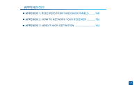
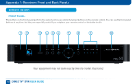
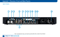
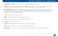
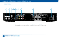
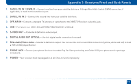
Appendix 1: Receivers Front and Back Panels 1. SATELLITE IN 1 (SWM-2) - Connect one line from your satellite dish here. A Single Wire Multi-Switch (SWM) connection, if applicable, is made to this satellite in port. 2. SATELLITE IN 2 - Connect the second line from your satellite dish here. 3. S-VIDEO OUT - A Standard-Definition video output. 4. RCA-Audio/Video Jacks - Standard-Definition output. You can use the entire row of RCA connectors (yellow, white and red) to feed a VCR or DVD player/burner. 5. COMPONENT VIDEO OUT- Use this block to connect up component video cables (green, blue, red) and use the white and red RCA connectors below it for analog audio out. 6. DIGITAL AUDIO OUT COAXIAL - Use this digital audio connection for sound. 7. DIGITAL AUDIO OUT OPTICAL - Use this digital audio connection for sound. 8. HDMI - Use this combination digital video and audio connector for the best picture quality. 9. ETHERNET - Please refer to Appendix 2 for information on networking options on your HD DVR before connecting anything to the Ethernet port. 10. USB - For future use. USB 2.0 Host(FRONT/REAR EACH 5V = 500mA) 11. SATA - Use this connector to add an external hard drive to your receiver. 12. PHONE JACK - Connect your phone line here to enable Pay Per View purchasing and Caller ID (if your phone service package includes it). 13. POWER - Your receiver must be plugged in at all times to function properly. 151
-
 1
1 -
2
-
3
-
4
-
5
-
6
-
7
-
8
-
9
-
10
-
11
-
12
-
13
-
14
-
15
-
16
-
17
-
18
-
19
-
20
-
21
-
22
-
23
-
24
-
25
-
26
-
27
-
28
-
29
-
30
-
31
-
32
-
33
-
34
-
35
-
36
-
37
-
38
-
39
-
40
-
41
-
42
-
43
-
44
-
45
-
46
-
47
-
48
-
49
-
50
-
51
-
52
-
53
-
54
-
55
-
56
-
57
-
58
-
59
-
60
-
61
-
62
-
63
-
64
-
65
-
66
-
67
-
68
-
69
-
70
-
71
-
72
-
73
-
74
-
75
-
76
-
77
-
78
-
79
-
80
-
81
-
82
-
83
-
84
-
85
-
86
-
87
-
88
-
89
-
90
-
91
-
92
-
93
-
94
-
95
-
96
-
97
-
98
-
99
-
100
-
101
-
102
-
103
-
104
-
105
-
106
-
107
-
108
-
109
-
110
-
111
-
112
-
113
-
114
-
115
-
116
-
117
-
118
-
119
-
120
-
121
-
122
-
123
-
124
-
125
-
126
-
127
-
128
-
129
-
130
-
131
-
132
-
133
-
134
-
135
-
136
-
137
-
138
-
139
-
140
-
141
-
142
-
143
-
144
-
145
-
 146
146 -
 147
147 -
 148
148 -
 149
149 -
 150
150 -
 151
151 -
 152
152 -
 153
153 -
 154
154 -
 155
155 -
 156
156 -
157
-
158
-
159
-
160
-
161
-
162
-
163
-
164
-
165
-
166
-
167
-
168
-
169
-
170
-
171
-
172
-
173
-
174
-
175
-
176
-
177
-
178
 |
 |