Danby DPAC8399 User Guide - Page 21
Remote Control Operating, Instructions, Instalación en la ventana, PRECAUCIÓN, Sugerencias para
 |
View all Danby DPAC8399 manuals
Add to My Manuals
Save this manual to your list of manuals |
Page 21 highlights
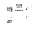
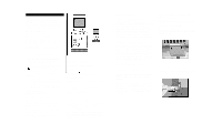
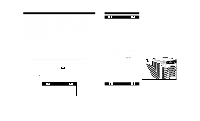
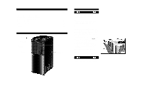
Sugerencias para ahorrar energía Su artefacto Danby ha sido diseñado para un rendimiento muy eficaz en ahorro de energía. Siga estas recomendaciones para una mayor eficacia. 1. Seleccione una graduación del termostato que se adapte a su requisitos de confort y déjelo en la graduación seleccionada. 2. El filtro de aire es muy eficaz en la remoción de partículas contenidas en el aire. Siempre mantenga limpio este filtro. 3. Use cortinas o persianas para evitar que la luz directa del sol penetre en la habitación y la caliente, pero no permita que las cortinas o persianas obstruyan la corriente de aire alrededor de la unidad. Instalación en la ventana Riesgo de choque eléctrico Para evitar la posibilidad de lesiones personales, desconecte la corriente a la unidad antes de instalarla o de repararla. PRECAUCIÓN Para evitar dificultades en la instalación/operación, es importante que lea bien estas instrucciones. Accesorios para la instalación - Figura 1 Descripción Canti dad Manguera flexible de escape con adaptadores 3/juego Se extiende de 19 1/2" (50 cm) hasta 74 3/4" (190 cm) Adaptador de escape de la ventana (boca plana 1 pieza Juego graduable de corredera para ventana/puerta de patio De 26 5/8" (67.5 cm) hasta 80" (203 cm 3/juego Conector para la manguera de desagüe 1 pieza Opción de desagüe continuo (manguera no incluida) Accesorios del tanque de agua externo Fig. 1a Bandeja de soporte y ruedita 1 pc Tanque externo y tapa 1 pc Conector rápid(Tanque externo 1 pc OBSERVACIÓN ESPECIAL: La extensión para la manguera de desagüe exterior (desagüe directo) no viene incluida con esta unidad y se puede adquirir a través de su tienda local de artículos de ferretería. ADVERTENCIA Cuando el juego de la puerta del patio se encuentre instalado, no será posible trabar la puerta del patio. Esta podría plantear un problema de seguridad. Se recomienda que instala un "perno de pie" o una "barra de proteción" detràs de la puerta. (disponible en cualquier tienda de ferretería local). 4. Encienda su acondicionador de aire antes de que el aire del exterior se vuelva caliente e incómodo. Esto evita un período inicial de incomodidad mientras la unidad está enfriando la habitación. El uso de la opción del RELOJ automático programable de arranque/parada puede darle una ventaja importante en estas situaciones, si se usa al máximo. 5. Cuando las temperaturas externas sean suficientemente frescas, apague el acondicionador de aire y use el MODO DE VENTILADOR en las posiciones ALTA, MEDIANAO BAJA. Esto hace que el aire del interior circule, proporcionando una cierta medida de confort de enfriamiento y utilice menos electricidad. El juego de escape/ventana debe estar instalado en todo momento cuando la unidad está funcionando en el modo de AIRE ACONDICIONADO. Debe haber por lo menos 11.8" (30 cm) de espacio libre entre la unidad y cualquier otro objeto o estructura construida. La unidad se debe instalar sobre una superficie nivelada. No es necesario instalar el juego para ventanas durante la operación de los otros tres modos. (Calefacción (DPAC7599)/Deshumidificación/Ventilación). Fig. 1 Accesorios para la instalación Manguera flexible de escape 19 1/2" - 74 3/4" Conector de la manguera de desagüe Adaptador de escape para la ventana Adaptador Adaptador Juego graduable de corredera para ventana/puerta de patio 26 5/8" - 80" Fig. 1 Accesorios del tanque de agua externo Bandeja de soporte y ruedita Conector rápid(Tanque externo) Remote Control Operating Instructions 1. Sending Signal: When the main unit is turned on (I/O button), this symbol (1A) will appear in the remote LCD window. The remote must be aimed directly at the control panel on the main unit when initiating commands. When a remote control button is depressed (excluding L, R, Clock, & set˚C/˚F), the following symbol " " flashes once in the remote LCD window. This symbol confirms that a signal was dispatched from the remote and a "Beep" from the main unit confirms the signal was received. The main unit will then recognize and respond accordingly to the selection made. All selections (excluding time of day settings) will appear immediately in the remote LCD window and main unit LCD window when the unit becomes operational. There may be a slight delay (2-5 seconds) before the main unit responds to the remote signal. This is normal. If the main unit does not respond, try the procedure again. If the main unit again fails to respond; Check the following: • Are the receiver and the remote unit within the required 7 meter (23 ft.) operating distance? • Is the receiver window on the main unit partially blocked and/or obscured? • Are the batteries correctly installed inside the remote (positive+/ negative-)? • Check the batteries. If low, replace. 2. Setting/Adjusting Time of Day Clock (Remote Control): When the batteries are installed, the clock displays "0:00" and the colons (:) flash. Push the "Temp/Timer" buttons to adjust the current time of day (0-24hrs). Each depression of the button will increase or decrease the time of day setting (1 min. increments). When the correct time of day has been established, push the "Set" button to activate the time of day clock setting (colons stop flashing). To change the time of day clock setting, push and hold the "clock" button (3 seconds) until the colons (:) flash. Adjust the time of day clock setting (time adjust buttons) then push the "Set" button to activate time of day clock setting (colons (:) stop flashing). NOTE: The time of day clock setting on the remote control unit operates independently and does not control the time of day clock setting on the main unit. 3. Mode Setting: Press the "Mode" button to select the desired operating mode. Each depression of the button will advance to a different setting (Auto-Cool-Dry-Heat-Fan). NOTE: The "Auto" mode is a built in feature, activated from the hand held remote unit only. (Auto mode cannot be programmed from the main unit control panel) Under the "Auto" mode, the unit will automatically select the operating mode, based on temperature selection. The main unit will respond automatically, switching appropriately between the "Auto-coolheat-fan" mode to maintain the program temperature selected. Dehumidifying does not respond/operate under the "Auto" mode function. 4. Temperature Setting: Press the remote buttons to select the desired "Temp/Timer" operating temperature. Each depression of the temperature button will increase/decrease the temperature settings (1°C increments, 2°F increments). The temperature selected will be displayed in the remote LCD window. Remote temperature ranges 17˚C-30˚C 5. Fan Speed Setting: Press the remote "Fan" button to select the desired operating fan speed. Depending on the mode selection, each depression of the fan button will advance to a different fan speed (Auto-Low-Medium -High) The fan speed selected will be displayed in the remote LCD window. i.e. MODE FAN SPEEDS Cool Auto/Medium-Low-Medium-High Heat Auto/Medium-Low-Medium-High Dry Auto (Medium Only) Fan Auto/Medium-Low-Medium-High "AUTO" is equivalent to "MEDIUM" (fan speed setting) on the main unit control panel. LCD Window 1 4 5 3 1A 2 7
-
 1
1 -
2
-
3
-
4
-
5
-
6
-
7
-
8
-
9
-
10
-
11
-
12
-
13
-
14
-
15
-
 16
16 -
 17
17 -
 18
18 -
 19
19 -
 20
20 -
 21
21 -
 22
22 -
 23
23 -
 24
24 -
 25
25 -
 26
26 -
27
-
28
-
29
-
30
-
31
-
32
-
33
-
34
-
35
-
36
 |
 |