Dell 1135N Service Manual
Dell 1135N Manual
 |
View all Dell 1135N manuals
Add to My Manuals
Save this manual to your list of manuals |
Dell 1135N manual content summary:
- Dell 1135N | Service Manual - Page 1
Dell 1133, 1135n Service Manual 07 Apr 2010 - Dell 1135N | Service Manual - Page 2
Inc. All rights reserved. Reproduction in any manner whatsoever without the written permission of Dell Inc.is strictly forbidden. Trademarks used in this text: Dell and the DELL logo are trademarks of Dell Inc. Other trademarks and trade names may be used in this document to refer to the entities - Dell 1135N | Service Manual - Page 3
in letter 2. Processor • Jupiter5 375 Mhz 3. Printer Language Emulations • SPL 4. Memory • 64 MB (Dell 1133) •128 MB (Dell 1135n) Mono Laser MFP Dell 1133 Dell 1135n 5. Interfaces • One USB port • One 10/100 Base TX network connector (Dell 1135n) 6. Toner cartridge • Initial : 0.7K • Sales : 1.5K - Dell 1135N | Service Manual - Page 4
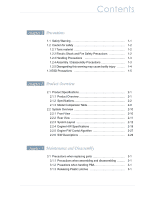
View 2-10 2.2.2 Rear View 2-11 2.2.3 System Layout 2-12 2.2.4 Engine H/W Specifications 2-19 2.2.5 Engine F/W Contol Algorithm 2-27 2.2.6 S/W Descriptions 2-29 chapter 3 Maintenance and Disassembly 3.1 Precautions when replacing parts 3-1 3.1.1 Precautions when assembling and disassembling - Dell 1135N | Service Manual - Page 5
3.4 Scanner and ADF 3-6 3.4.1 ADF unit 3-6 3.4.2 ADF roller 3-7 3.4.3 OPE Unit 3-8 3.4.4 Platen unit 3-8 3.4.5 CIS unit 3-9 3.5 Middle Cover 3-10 3.6 Fuser Unit 3-12 3.6.1 Whole Fuser Unit 3-12 3.6.2 Main Service parts of Fuser Unit 3-13 3.6.3 Replacing the Main Service part of Fuser Unit - Dell 1135N | Service Manual - Page 6
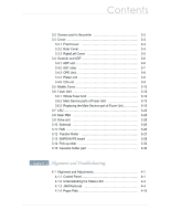
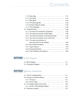
environment of the software 4-61 4.2.6 Fax & Phone Problems 4-64 4.2.7 Copy Problems 4-73 4.2.8 Scanning Problems 4-77 4.2.9 Fuser Problems and solutions 4-80 chapter 5 System Diagram 5.1 Block Diagram 5-1 5.2 Connection Diagram 5-2 chapter 6 Reference Information 6.1 Tool for Troubleshooting - Dell 1135N | Service Manual - Page 7
Contents attached Exploded Views & Parts List-OK * Please see the attached. Power Cord 4 Thumbnail 5 1. MAIN 7 2. COVER 9 3. COVER-MIDDLE ASSY 11 4. COVER FRONT 13 5. COVER REAR 15 6. FRAME BASE-LOWER 17 7. DRIVE MAIN-BRACKET 21 8. FRAME BASE-PICK UP 23 9. FUSER 25 10. CASSETTE 27 11. - Dell 1135N | Service Manual - Page 8
closely. 1.1 Safety Warning (1) Only to be serviced by appropriately qualified service technician. High voltages and lasers inside this product are dangerous. This printer should only be serviced by a qualified service technician. (2) Use only Dell replacement parts There are no user serviceable parts - Dell 1135N | Service Manual - Page 9
. Do not touch the machine or the power cord if it is still connected to the wall socket in these weather conditions. (10) Avoid damp or dusty areas, install the printer in a clean well ventilated location. Do not position the machine near a humidifier, or in front of an air conditioner. Damp and - Dell 1135N | Service Manual - Page 10
beside on open window or close to a humidifier or heater. Damage could be caused to the printer in such areas. (5) Do not place candles, burning cigarettes, etc on the printer, These could cause a fire. 1.2.4 Assembly / Disassembly Precautions Replace parts carefully, always use Dell parts. Take care - Dell 1135N | Service Manual - Page 11
, do not put hand or hair into the rotating parts (Paper feeding entrance, motor, fan, etc.). (3) When you move the printer. This printer weighs 23.34 lbs (Dell 1133) / 25.44 lbs (Dell 1133n) including toner cartridge and cassette. Use safe lifting and handling techniques. Use the lifting handles - Dell 1135N | Service Manual - Page 12
commercially available wrist strap device, which should be removed for your personal safety reasons prior to applying power to the unit under replacement ESD from its protective packaging until immediately before installing it. Most replacement ESDs are packaged with all ESD. Service Manual 1-5 - Dell 1135N | Service Manual - Page 13
• Jupiter5 375 Mhz 3. Printer Language Emulations • SPL 4. Memory • 64 MB (Dell 1133) •128 MB (Dell 1135n) . Interfaces • One USB port • One 10/100 Base TX network connector (Dell 113 n) 6. Toner cartridge • Initial : 0.7K • Sales : 1.5K / 2.5K two types 7. ADF (Dell 1135n) 2-1 Service Manual - Dell 1135N | Service Manual - Page 14
Mac 10.3, 10.4, 10.5 Mac 10.3, 10.4, 10.5 WHQL Windows 2000, XP, 2003 Server, Vista(32/64bits) Windows 2000, XP, 2003 Server, Vista(32/64bits) Wired network N/A Protocol TCP/IP, Ethertalk, SNMP, HTTP 1.1 Wired network N/A Supporting OS Windows 2000/XP(32/64bits)/2003 Server/Vista(32 - Dell 1135N | Service Manual - Page 15
370W Save : Less than 10W Power off : Less than 1W 142 pages 12,000 pages 10,000 pages 30 min. 20,000 sheets or 5 years (whichever comes first) N/A SET Life Cycle 50,000 sheets or 5 years (whichever comes first) Dell 1135n Ready : Less than 45W Average : Less than 370W Save : Less than 10W Power - Dell 1135N | Service Manual - Page 16
only) N/A Manual 2.1.2.4 Scan Specifications Items Scanning Device Supported OS Compatibility Maximum Scan Width Effective Scan Width Optical Resolution Interpolated Resolution Preview Scan Dell 1133 Color 1200 dpi CIS (Contact Type Image Sensor) Module Windows 98/Me/NT4.0/2000/XP, Various Linux - Dell 1135N | Service Manual - Page 17
Scan Modes/Speeds: (PC Environment : Win XP, P4-2.4GHz, 512M RAM, 300 dpi, Letter, USB1.1, Photoshop 6.0.1) Dell 1133 Line Art, Halftone : 15 sec on Platen Gray : 23 sec on Platen 256 Color 300 dpi : 65 sec on Platen True Color 300dpi : 65 sec on Platen ADF Capacity: N/A Dell 1135n User - Dell 1135N | Service Manual - Page 18
Sensing 2nd Tray Capacity Manual Tray Capacity Media Sizes Media types Media weight Sensing Output Stacking Printable Area Non-Printable Area ADF Capacity ADF Document Size Media Size (for Fax and Copy) Dell 1133 Dell 1135n 250-sheets Cassette Tray, 1-sheet Multi Purpose Tray @ 80g/້ 250 - Dell 1135N | Service Manual - Page 19
ISO/IEC 19752. Electronic key(CRUM) Only Electronic key(CRUM) Only 2.1.2.8 Consumables (FRU) Item Image Fuser Transfer Roller Pick up Roller Part code Life JC91-00945A(220V) 50K JC91-00946A(110V) JC66-01218A 50K JC93-00087A 50K Cassette holder pad JC90-00941A 50K 2-7 Service Manual - Dell 1135N | Service Manual - Page 20
Memory SCF PS Dell 1133 N/A N/A N/A N/A Dell 1135n Yes N/A N/A N/A * Print speed will be affected by Operating system used, computing performance, application software, connecting method, May be affected by operating environment, printing interval, media type and media size 2-8 Service Manual - Dell 1135N | Service Manual - Page 21
600 x 600 dpi Scan To PC 600 x 600 dpi 4800 x 4800 dpi 33.6 Kbps 2 MB 150 sheets 30 sheets USB 2.0 3K (1K) 22ppm 2,400 x 600 dpi GDI 10 sec from ready 600 x 300 dpi Scan To PC 600 x 2,400 dpi 9,600 x 9,600 dpi 14.4 Kbps 16 MB 250 Cassette 35 sheets USB 2.0, N/W 1.5K/2.6K (1K) 2-9 Service Manual - Dell 1135N | Service Manual - Page 22
guides 8 Tray 1 3 Document feeder input tray 9 Manual tray 4 Document feeder output tray 10 Front door 5 Output support 11 Document output tray 6 Front door handle 12 Control panel 13 Toner cartridge 14 Manual tray paper width guides 15 Scanner lid 16 Scanner glass 2-10 Service Manual - Dell 1135N | Service Manual - Page 23
2.2.2 Rear View Product specification and feature This illustration may differ from your machine depending on its model. 1 Network port 5 Power receptacle 2 USB port 6 Rear door 3 Telephone line socket 7 Rear door handle 4 Extension telephone socket (EXT) 2-11 Service Manual - Dell 1135N | Service Manual - Page 24
the main control board, power board, operation panel, PC Interface. 6 7 5 1 15 2 14 13 3 4 12 11 8 10 9 1 Top out-bin delivery roller 2 Fusing roller 3 LSU 4 Toner Cartridge 5 OPE 6 ADF 7 Platen 8 Feed roller Service Manual 9 Separation Pad 10 Pick up roller 11 Transfer roller 12 OPC 13 - Dell 1135N | Service Manual - Page 25
function, paper detecting function, jam removing function, and so on. 5) Manual tray It has a paper registration [skew correction] function, paper transferring function, jam removing function, and so on. It uses manual feed method to feed 1 sheet of paper and 1 envelope. 2-13 Service Manual - Dell 1135N | Service Manual - Page 26
In Dell 1133/1135n, the driving device consisted of Φ55 BLDC motor, OPC, Pick- up, Feed, gear block all mounted as an assembly. • Driving Frequency: BLDCΦ55 Motor : 2200rpm(1650 Clock) • It is a power delivery unit by gearing: BLDCΦ55 Motor - >Pickup/Feeder/Developer/Fuser/Duplex 2-14 Service Manual - Dell 1135N | Service Manual - Page 27
is made of a silicon resin, and the surface also is coated with Teflon. When a paper passes between a heat roller and a pressure roller, toner adheres to the surface of a paper permanently. 5) Halogen Lamp - Voltage 120 V : 115 ± 5 % 220 V : 230 ± 5 % - Capacity : 750 Watt ± 25 W 2-1 Service Manual - Dell 1135N | Service Manual - Page 28
device: Thermostat cuts off main power. Safety device - A fuser power is cut off when a front cover is opened - Maintain a temperature of fuser cover's surface under 80ଇ for user, and attach a caution label at where customer can see easily when customer open a rear cover. 2-16 Service Manual - Dell 1135N | Service Manual - Page 29
on paper. The /HSYNC signal is used to synchronize the image data with the left margin of the paper. The one side of the polygon mirror is one line for scanning. OPC Drum Photo Diode LD Driver circit Protector panel LD(Laser Diode) Polygon Mirror Polygon Motor Motor Driver 2-17 Service Manual - Dell 1135N | Service Manual - Page 30
cleaning blade. • Handling of wasted toner : Waste [residual] toner is cleaned off the drum by means of a cleaning blade. • OPC Drum Protecting Shutter : None • Classifying device for toner cartridge: ID is classified by CRUM. 8 100 6 7 5 3 17 2 1 0 20 720 150 ˨ 450 4 5 800 2-18 Service Manual - Dell 1135N | Service Manual - Page 31
the circuits for the motors: paper feed, paper path, clutches, pre- transfer lamp, current control to driver components, and fan driving. The signals from the paper feed jam sensor and paper empty sensor are directly inputted to the main board. CIS FUSER PLATEN MOTOR OPE ADF PPLLAATTEENN - Dell 1135N | Service Manual - Page 32
- 32 MB address space per each channel • MAC - 10M/100Mbps - Full IEEE 802.3 Compatibility • Engine Controller - LSU Interface Unit - Step Motor : 2 Channels - PWM : 8 Channels - ADC : 4 Channels (b) Memory • Flash Memory : It stores System Program and downloads the System Program through PC - Dell 1135N | Service Manual - Page 33
sensors do not detect that the correct cartridge is inserted, the CPU will display the toner cartridge is invalid, it will show invalid sign on a LED. ■ Paper Exit Sensing The Paper Exit Sensor is mounted on the Fuser Unit exit side, and is used to ensure that paper has indeed exited the machine. If - Dell 1135N | Service Manual - Page 34
for THV/MHV/BIAS, and supplied to the high voltage, OPC cartridge, and transfer roller for optimum latent image and toner transfer quality. It is the power source of entire system. It system, and AC to power the Fuser Unit. SMPS has two output channels, which are +5V and +24V. 24 2-22 Service Manual - Dell 1135N | Service Manual - Page 35
: 50 ms Max - Output Voltage Falling Time : 50 ms Max - Output Control Signal (BIAS-PWM) : the CPU is HV output when PWM is low 2-23 Service Manual - Dell 1135N | Service Manual - Page 36
A 1.2 A Under 100mVp-p 5.0W 6.0W Shut down or Fuse Protection (Under LPS spec) CH2 +24.0V CON 14 24V PIN : 5,6 GND PIN : 4,8,13,14 +24V ± 10% (21.6 ~ 26.4V) 2.0 A 2.3 A Under 500mVp-p 43.2W 55.2W Remark CON 14 24VS PIN : 9,10,11 Shut down(2.8A~4.5A) or Voltage Drop(tnip-10%) 2-24 Service Manual - Dell 1135N | Service Manual - Page 37
Product specification and feature 2.2.4.3 Fax Our fax feature is based on Conexant DAA (Data Access Arrangement) ) : This Modem Chip LIU (Line Interface Unit) is controlled by SSD and satisfies each PSTN requirement by modulating the internal configuration with connecting Tel Line. 2-2 Service Manual - Dell 1135N | Service Manual - Page 38
portion is read by CIS Pixel data in 1200dpi Line and processed using an Error Diffusion Algorithm on Text mode and Photo mode. When scanning at machine and/or on PC Scan, the data is stored in a Scan Buffer without algorithm. Shading and Gamma Correction are executed immediately in every mode, then - Dell 1135N | Service Manual - Page 39
Paper Jam protocols are as follows: Item JAM 0 JAM 1 JAM 2 Description - After picking up, paper cannot be entered due to paper is not fed. - After picking up, paper to the PWM duty. The transfer voltage admitted when the paper passes the transfer roller is decided by environment recognition. The - Dell 1135N | Service Manual - Page 40
disabled. The table below lists the types of Fuser Errors that can occur: • Open Heat Error During warmup, if the Fuser Unit does not reach its proper operating temperature within a predetermined time an "Open Heat Error will occur. An error message will be displayed on the Control Panel alerting - Dell 1135N | Service Manual - Page 41
application software that can operate in a Windows and/or Web Environment. 2) The Firmware portion is an Embedded software controlling the print job. 2.2.6.2 Architecture Host Software is made up of: 1. Graphic User Interface that offers the various editing functions to user in Host. 2. Driver that - Dell 1135N | Service Manual - Page 42
Diagram above. Host Side is made up of: 1. The Print Driver that is Windows application software translates printed data to one of printer languages and creates spooler file. 2. Web-based Application offer a them from spooler to network port, and offer the result of printing). 2-30 Service Manual - Dell 1135N | Service Manual - Page 43
data to required paper with the sequential developing process. The additional printing function are realized in: (1) Web environment (2) Window environment In addition, Kernel informs the printing and printer status to end-user making the printing job with the Status Monitor. 2-31 Service Manual - Dell 1135N | Service Manual - Page 44
utio s whe ssem li d dis ssem li Use only approved Dell spare parts. Ensure that part number, product name, any voltage, current or temperature rating are unit. Once it is disassembled dust is admitted to the mirror chamber and will seriously degrade print quality. There are no serviceable parts - Dell 1135N | Service Manual - Page 45
printer. Please ensure that, when you disassemble the printer, you keep a note of which screw is used for which part and that, when reassembling the printer, the correct screws are used in the appropriate places. ■ Dell 1135n Part ,L3,HE D 3 S EW M3,L6, OU D HE D,WITH WOSHE 1 3-2 Service Manual - Dell 1135N | Service Manual - Page 46
■ Dell 1133 Part Code oc tio Descri tio ty 6 3- 196 S EW-T PT PE PWH, ,B,M3,L1 , I PLT,SW H1 2 6 3- 261 assette S EW-T PT PE BH, ,-,B,M3,L6, P (WHT),SW H1 ,- 1 6 3- 264 S EW-T PT PE PWH, ,-,B,M3,L6, P (WHT),SW H1 ,- 1 6 3- 196 S EW-T PT PE PWH, ,B,M3,L1 , I PLT,SW H1 1 6 3- 269 user - Dell 1135N | Service Manual - Page 47
3.3 Cover 3.3.1 Front Cover 1. Take off the cassette. Dis ssem ly d e ssem ly 2. Take off the front cover by removing both hooks. 3.3.2 Rear Cover 1. emove screws on back side of printer. 2. emove the rear cover. 3-4 Service Manual - Dell 1135N | Service Manual - Page 48
Dis ssem ly d e ssem ly 3.3.3 Right/Left Cover 1. emove the front cover and rear cover. 2. Lift up the scanner slightly. 3. emove the Left ight cover by removing hooks of right left top bottom side. 3Service Manual - Dell 1135N | Service Manual - Page 49
Dis ssem ly d e ssem ly 3.4 Scanner and ADF 3.4.1 ADF unit 1. emove the D connector cover. 2. Unplug the connector. 3. Lift the D unit up and release it. 3-6 Service Manual - Dell 1135N | Service Manual - Page 50
Dis ssem ly d e ssem ly 3.4.2 ADF roller 1. emove 3 E-rings. 2. Pull the shaft to the direction of arrow. 3. Take off the D roller assembly. 3-7 Service Manual - Dell 1135N | Service Manual - Page 51
Dis ssem ly d e ssem ly 3.4.3 OPE Unit 1. Pull up the OPE unit. There are 4 hooks. 2. Take off the OPE PB after remove 4 screws and 2 connectors. 3.4.4 Platen unit 1. emove the OPE unit. 2. emove 2 screws. 3. Lift up cover scan upper. 3Service Manual - Dell 1135N | Service Manual - Page 52
3.4.5 CIS unit 1. emove IS cable. 3. Lift IS and release it. Dis ssem ly d e ssem ly 3-9 Service Manual - Dell 1135N | Service Manual - Page 53
Dis ssem ly d e ssem ly 3.5 Middle Cover 1. emove the rear left right cover. 2. Unplug 4 connectors including a lat cable. 3. Lift up the scanner slightly. 4. Push up both hooks from the bottom of middle cover. 3-1 Service Manual - Dell 1135N | Service Manual - Page 54
Dis ssem ly d e ssem ly . Lift up the scanner slightly angle 7 双 and remove the scanner. 7. elease the middle cover after removing 4 screws. 6. Unplug 1 connector. 3-11 Service Manual - Dell 1135N | Service Manual - Page 55
Dis ssem ly d e ssem ly 3.6 Fuser Unit 3.6.1 Whole Fuser Unit 1. emove the rear and left cover. 2. emove 4 screws. 3. Unplug the 2 connectors from SMPS board and Main board. 4. Take off the user unit. 3-12 Service Manual - Dell 1135N | Service Manual - Page 56
d e ssem ly 3.6.2 Main Service parts of Fuser Unit Photo P rt code P rt me 1 61 7- 1 2 SP I ES 2 4713- 1212 (22 ) L MP-H LO E 3 39- 19 H ESS USE OI T 4 39- 1 2 H ESS- USE 67- 41 P USE L MP L 6 67- 414 P USE L MP 7 61 7- 116 SP I TS 66- 2364 TU TO E IT 3-13 Service Manual - Dell 1135N | Service Manual - Page 57
14 61- 36 UIDE L W 1 61 7- 1 SP I TS 16 72-4 361 PMO OLLE E IT 17 61-7 976 SP I ET USE E IT 1 O EL 7 2-13 E SE BE I 3-14 Service Manual - Dell 1135N | Service Manual - Page 58
Dis ssem ly d e ssem ly 3.6.3 Replacing the Main Service part of Fuser Unit 3.6.3.1 Spring-Es Separate it as take up the circle-area of Spring-Es from hook. 2 3-1 Service Manual - Dell 1135N | Service Manual - Page 59
the checking point and push to right side, and then disassemble. 3. Disassemble Spring-Ts from the actuator. aution : Do not touch the roller surface of fuser inside 2. Disassemble ctuator-Exit from Holder- ctuator. 3-16 Service Manual - Dell 1135N | Service Manual - Page 60
Dis ssem ly d e ssem ly 3.6.3.3 Cap-Fuser lamp R/Cap-Fuser Lamp L Press the hook end of latch away from the cover-fuser to which it is latched and separate it - Cap-Fuser Lamp L - Cap-Fuser Lamp R aution : Don t bend the stud 3-17 Service Manual - Dell 1135N | Service Manual - Page 61
Dis ssem ly d e ssem ly 3.6.3.4 Lamp HalogenG 1. Pull out the harness (Harness- user oint, Harness- user ) which is connected at user Lamp Halogen. nd loose the two screws ( Left side, ight side each one ) in the red circle. 2. elease the Lamp Halogen. 3-1 Service Manual - Dell 1135N | Service Manual - Page 62
Joint and Harness-Fuser AC 1. Pull out the connected part from L ( efer to 3.4.3.4 Lamp-Halogen disassemble method). 2. Pull out the connected part from Thermostat. nd separate the harness from the user. # 3.6.3.6 Thermostat Loose the two screws in the red circle and separate it. 3-19 Service Manual - Dell 1135N | Service Manual - Page 63
Dis ssem ly d e ssem ly 3.6.3.7 Lever Link Jam R/ Lever Link Jam LGG fter removing the E-ring and Washer-Plain , separate the lever. - Cap-Fuser Lamp R - Cap-Fuser Lamp L 3-2 Service Manual - Dell 1135N | Service Manual - Page 64
ly d e ssem ly 3.6.3.8. Guide InputG After loose the fixed one screw on Guide Input, Disassemble it. 3.6.3.9. Pmo Roller Exit / Spring Etc Fuser ExitG 1. Disassemble Spring-Etc user Exit. 2. Disassemble Pmo- oller Exit. aution : Do not touch the roller surface of fuser inside 3-21 Service Manual - Dell 1135N | Service Manual - Page 65
Dis ssem ly d e ssem ly 3.6.3.10 Guide Claw / Spring Ts(6107-001800) 1. Disassemble Spring-Ts. 3. eep holding and push to underneath. 2. Turn around the uide-claw. aution : Do not touch the roller surface of fuser inside. 3-22 Service Manual - Dell 1135N | Service Manual - Page 66
Dis ssem ly d e ssem ly 3.7 LSU 1. emove the Middle cover ( efer to 3. ) 2. emove 3 screws and unplug 2 connectors. 3. elease the LSU from the rame. 3-23 Service Manual - Dell 1135N | Service Manual - Page 67
Dis ssem ly d e ssem ly 3.8 Main PBA 1. emove the left cover. 2. Take off the -cover after removing 1 screw. 3. Take off the Main PB after removing 4 screws and all connectors. 3-24 Service Manual - Dell 1135N | Service Manual - Page 68
Dis ssem ly d e ssem ly 3.9 Drive unit 1. emove the Main PB (refer to 3). 2. Take off the PB shield after removing 4 screws. 4. Take off the Drive Unit after removing 1 connector. 3. emove 6 screws. Note : emove the motor of drive unit after removing 4 screws if necessary. 3-2 Service Manual - Dell 1135N | Service Manual - Page 69
Dis ssem ly d e ssem ly 3.10 Solenoid 1. emove the Drive unit (refer to 3). 2. Take off the solenoid after removing 1 screw. 3. To remove the solenoid B , take off the removing 1 screw. 3.11 FAN 1. emove the right cover. 2. emove 1 screw and 1 connector. 3. Take off the . 3-26 Service Manual - Dell 1135N | Service Manual - Page 70
Dis ssem ly d e ssem ly 3.12 Transfer Roller 1. Open the front cover. 2. Take out the toner cartridge. 3. Take off the transfer roller by release its right shaft from hook. Cautions : Do not touch the surface of the Transfer oller. 3-27 Service Manual - Dell 1135N | Service Manual - Page 71
Dis ssem ly d e ssem ly 3.13 SMPS/HVPS board 1. Take out the assette unit. 2. emove rear right cover (refer to 3.3.3 rear cover). 3. emove 11 screws (bottom x 9, rear x 2 ) and 2 connector (SMPS x 1, an x 1). 4. Turn the board shield over as shown below. Unplug the connector. 3-2 Service Manual - Dell 1135N | Service Manual - Page 72
Dis ssem ly d e ssem ly . Take off the SMPS H PS board after removing 9 screws and connector. 3-29 Service Manual - Dell 1135N | Service Manual - Page 73
Dis ssem ly d e ssem ly 3.14 Pick up roller 1. Take out the assette unit. 2. arefully turn the printer over. 3. Take off the pick up roller after removing 1 screw. 3.15 Cassette holder pad 1. Take out the assette unit. 2. Take off the holder pad by unhooking both latches. 3-3 Service Manual - Dell 1135N | Service Manual - Page 74
Panel ■ Dell 1135n This control panel may differ from your machine depending on its model. 1 ID Copy 2 Reduce/Enlarge 3 Display 4 Status 5 (Fax) 6 (Copy) 7 (Scan) 8 Arrow 9 Menu You can copy both sides of the ID Card like a driver's license to a single side of paper. Makes a copy - Dell 1135N | Service Manual - Page 75
Energy Saver Starts a job. Stops an operation at any time. The pop-up window appears on the screen showing the current job that the user can stop or resume. Sends the machine into power saver mode. If you press and hold this button, you can also turn the power on and off. Service Manual 4-2 - Dell 1135N | Service Manual - Page 76
both sides of the ID Card like a driver's license to a single side of paper. Sends scanned data. Makes a copy smaller or larger than the original. Stops an operation at any time. The pop-up window appears on the screen showing the current job that the user can stop or resume. Starts a job. Sends - Dell 1135N | Service Manual - Page 77
It is recommended to replace the toner cartridge. • A paper jam has occurred. • The cover is opened. Close the cover. • There is no paper in the tray. Load paper in the tray. • The machine has stopped due to a major error. Check the display message. a. Estimated cartridge life means the expected or - Dell 1135N | Service Manual - Page 78
2. Open the document feeder cover. 4. Close the document feeder cover. Reload the originals you removed, if any, in the document feeder. 3. Gently remove the jammed original from the document feeder. 5. Open the scanner lid. * If you see no paper in this area, go to step 5. Service Manual 4-5 - Dell 1135N | Service Manual - Page 79
the original from the feed area by carefully pulling it to the right using both hands. 7. Close the scanner lid. Load the removed pages back into the document feeder. Note: Ensure the number of originals you place in the ADF does not exceed its tray capacity. 1 scanner lid Service Manual 4-6 - Dell 1135N | Service Manual - Page 80
facing up in the manual tray. 4.1.3.3 Clearing paper jams When a paper jam occurs, a warning message appears on the display. To resume printing after clearing paper jams, you must open and close the front door. In tray 1 1. Open and close the front door. The jammed paper is automatically ejected - Dell 1135N | Service Manual - Page 81
and Troubleshooting In the manual tray 1. If the paper is not feeding properly, pull the paper out of the machine. Inside the machine 1. Open the front door and pull the toner cartridge out, lightly pushing it down. 2. Open and close the front door to resume printing. 2. Remove the jammed paper - Dell 1135N | Service Manual - Page 82
and Troubleshooting In exit area 1. Open and close the front cover. The jammed paper is automatically ejected from the machine. If you do not see the jammed paper, go to next step. 2. Gently pull the paper out of the output tray. 5. Pull the fuser cover levers down and remove the paper. Return - Dell 1135N | Service Manual - Page 83
4.1.4 Paper Path Alignment and Troubleshooting Sc er P rt i e P rt Sc er P rt i e P rt Service Manual 4-10 - Dell 1135N | Service Manual - Page 84
(Print, Copy, Scan) - Dell 1135n : 4 in 1 Network Model (Print, Copy, Scan, Fax, Network) System Setu Machine Setup Machine ID Machine ax o. Date Time lock Mode Language Default Mode Power Save Timeout ob Timeout ltitude dj. Toner Save Paper Setup Paper Size Paper Type Paper Source Wide 4 Sound - Dell 1135N | Service Manual - Page 85
Alignment and Troubleshooting 4.1.6 Tech Mode In service (tech) mode, the Model "Menu → ID Copy → Left → Right → Menu → Back" And the LCD briefly displays 'Tech Mode', the machine has entered service tech mode. After entering the tech mode, select the item you want by using a button on control panel - Dell 1135N | Service Manual - Page 86
Test Restart Machine All Report Configuration Supplies Info Error Info Protocol Dump Usage Page ComponentCheck Service Support Depth3 -9~-15 [Hi]=xx, [Lo]=xx 0~9 Tone,Pulse 33.6, 28.8, 14.4, 12.0, 9.6, 4.8 5%, 10% Depth4 -12 Tone 33.6 10% [1-30]% : 10 Total Page Count Enter Password Off* On On - Dell 1135N | Service Manual - Page 87
toner cartridge. Clear Count This function resets Total Page Count, Flatbed Scan Count, ADF Scan Count. Engine Footer This function is for monitoring the engine status. If you perform this function, at printing, the setting value for engine is shown on the bottom of the printed page. Service Manual - Dell 1135N | Service Manual - Page 88
This function is to get the optimum scan quality out of the CCD(Charge Coupled Device). If the copy image quality is poor, perform this function to check the condition of the CCD unit. Restart Machine You can reboot the machine by using a key without mechanically rebooting. Service Manual 4-15 - Dell 1135N | Service Manual - Page 89
Alignment and Troubleshooting Report ■ Configuration Report This report shows the status of the user-selectable options. You may print this list to confirm your changes after changing settings. - Dell 1135n Service Manual 4-16 - Dell 1135N | Service Manual - Page 90
Alignment and Troubleshooting Service Manual 4-17 - Dell 1135N | Service Manual - Page 91
Alignment and Troubleshooting ■ Supplies Information Report This report shows the status of toner cartridge. This report includes toner remaining, average area coverage, installed date etc. Service Manual 4-18 - Dell 1135N | Service Manual - Page 92
Alignment and Troubleshooting 4.1.7 EDC Mode The EDC Mode is used to independently control and test each sensor and driver component, so as to more easily service the printer. ■ Method to enter 1. After turn on the system power, check the "Ready" message on the LCD. 2. To enter the EDC Mode, Push - Dell 1135N | Service Manual - Page 93
LCD. If the front cover closed, "Closed" message display LCD. Description Manually open and close the actuator of the sensor [Regi, Feed, and/or Exit Sensor] you wish to check, the message "Without Paper" and "With Paper" message will be displayed. Manually open and close the actuator of the Empty - Dell 1135N | Service Manual - Page 94
Diagnostic Control • F/W - Firmware • HVPS - High Voltage Power Supply • H/W - Hardware • LD - Laser Diode • LSU - Laser Scanning Unit • MHV - Main High Voltage (Charge Voltage) • OPC - Optical Photo Conductor • SCF - Second Cassette Feeder • THV - Transfer High Voltage Service Manual 4-21 - Dell 1135N | Service Manual - Page 95
Troubleshooting 4.1.8 Firmware "Stop / Clear" Button. - It displays download mode message. 2. Send ROM file via USB. 3. Dell 1135n)# " Menu → ID Copy → Left → Right → Menu → Start " (Dell 1133)#after updating Rom file. Notice : All of count values and data saved in MFP will be cleared. Service Manual - Dell 1135N | Service Manual - Page 96
line and periodic band Toner artridge Periodic Band by little difference of density host, Damaged image by abnormal transfer Transfer roller Background user Black spot and image ghost 7 32 4 6 1 5 1 OP 2 Developing oller 3 harging roller 4 Supply oller Service Manual Tranfer roller - Dell 1135N | Service Manual - Page 97
the tray number. • [media type] indicates the media type. • [media size] indicates the media size. • [color] indicates the color of toner or imaging unit. Message [COMM. Error] [Incompatible] [Line Error] [No Answer] [Stop Pressed] ADF COVER OPEN ERROR BOOTP problem Auto IP Run BOOTP problem Recon - Dell 1135N | Service Manual - Page 98
Alignment and Troubleshooting Message DHCP problem: Auto IP Run Document Jam. Remove Jam Door Open. Close it Error #02-000~2 Turn off then on Install Toner Install it Memory Full Remove Job Network Problem: IP Conflict Not Compatible Toner cartridge Output bin Full Remove paper Meaning Suggested - Dell 1135N | Service Manual - Page 99
Alignment and Troubleshooting Message Paper Empty in Tray1 Paper Jam in exit area Paper Jam in MP Tray Paper Jam in Tray1 Paper Jam inside machine Prepare new cartridge Replace new cartridge Meaning Suggested solutions There is no paper in the indicated tray. 1. Load paper in the tray. 2. If the - Dell 1135N | Service Manual - Page 100
Alignment and Troubleshooting Message Replace Toner Self Diagnostics Please wait Sleeping... Too many Faxes Remove Job Meaning The cartridge is out of toner. The engine in your printer is checking some problems detected. The machine is in the power save mode. Too many faxes are received. - Dell 1135N | Service Manual - Page 101
the customer. Power On Green LED on? Ready or Power save Test Print printing Quality is Nomal? END - No Power - Power Module error - Main PBA error - Panel PBA error Error LED ON? Check the error message. ( Refer to 4.1.10 Error message) Refer to "Solution of Image Problem" Service Manual 4-28 - Dell 1135N | Service Manual - Page 102
surface of the charge roller in the toner cartridge. If causes 1 and 2 occur in the toner cartridge, replace the toner cartridge and try to print out. 3. Partly depression or deformation on the surface of the transfer roller. Replace the transfer roller if occurred as No. 3. Service Manual 4-29 - Dell 1135N | Service Manual - Page 103
Open the front cover and check ribs that corresponds to the position of the voids. Remove if found. If the problems are not solved, replace the toner cartridge. 6. Partly depression or deformation on the surface of the transfer roller Replace the transfer roller if occured as NO.6 Service Manual - Dell 1135N | Service Manual - Page 104
Alignment and Troubleshooting 3) Horizontal Black Band Description : terminal of the Charge, Supply, Develop and Transfer roller.(remove the toner particles and paper particles) 2. The rollers of developer may be stained. OPC Drum malfunction persists, replace the developer. Service Manual 4-31 - Dell 1135N | Service Manual - Page 105
has expired [50.000 sheets]. Replace it. 2. In case of 47 mm interval unremovable in 1, take measures as to replace the developer cartridge and try to print out. 3. Clean the inside of the set against the paper particles and foreign matter in order not to cause the trouble. Service Manual 4-32 - Dell 1135N | Service Manual - Page 106
is light. No 1 : Replace the toner cartridge and try to print out. No 2 : Instruct the customer that the machine has to be at average room temperate in order to produce good copy quality. No3 : Clean any contaminated terminals. Replace the HVPS if the problems any contaminated terminals. not solved - Dell 1135N | Service Manual - Page 107
Alignment and Troubleshooting 6) Dark Image or a Toner cartridge and charge terminal of HVPS. 1. Clean the high voltage charge terminal. 2. Replace the HVPS if not solved by the above direction 1 and 2. 3. VD0 signal of the Main PBA is Low state. Replace the LSU Unit or Main PBA. Service Manual - Dell 1135N | Service Manual - Page 108
left and right Spring Holder. 2. The life of the Toner cartridge has expired. Occur in the toner cartridge gently shake the toner cartridge. 3. The toner level is not even on the toner cartridge roller due to the bad blade. Replace the toner cartridge and try to print out. Service Manual 4-35 - Dell 1135N | Service Manual - Page 109
the life span of it has been ended. 4. Is the movement(Up and Down) of the transfer roller smooth? Clean the bushing part of the transfer roller. 5. Is the HVPS normal? 1. If the problem is still not solved, replace the toner cartridge. 2. Gently shake the toner cartridge. Service Manual 4-36 - Dell 1135N | Service Manual - Page 110
to print out. 3. The life of toner cartridge is expired. Replace the engine board if not solved by the above directions 1-2. 4. Transfer roller lifetime(50K sheets) has expired. Continue.. If not solved by the direction 3, check the transfer roller lifetime and replace it. Service Manual 4-37 - Dell 1135N | Service Manual - Page 111
low temperature (below 10). 6. Damaged cleaning blade in the toner cartridge. Instruct the customer that the machine has to be at average room temperate in order to produce good copy quality. Occur in the toner cartridge, replace the toner cartridge and try to print out. Service Manual 4-38 - Dell 1135N | Service Manual - Page 112
using manual feeder) 75 5 When printing on card stock thicker than normal paper or transparencies such as OHP, higher transfer voltage is required. Select 'Thick Mode' on paper type menu from the software application and after using returning to the original mode is recommended. Service Manual - Dell 1135N | Service Manual - Page 113
Alignment and Troubleshooting 11) Ghost (3) : Fuser Description : Ghost occurs at 75.4 mm or 77.5mm intervals. 75 4 77 5 The temperature of the fuser is being maintained too high. Disassemble the fuser Unit. Clean the Fuser Rollers, and Thermistor. (Caution: can be deformed) Service Manual 4-40 - Dell 1135N | Service Manual - Page 114
may be expired. 2. The abnormal voltage and bad contact of the terminal of the supply roller Occur in the developer cartridge, replace the developer and try to print out. Check the approved voltage of the supply roller and contact of the terminal and adjust if necessary. Service Manual 4-41 - Dell 1135N | Service Manual - Page 115
sealed toner cartridge. 2. If the transfer roller is contaminated, stains on the face of page will occur. Replace the toner cartridge. If the transfer roller is contaminated, run PC Cleaning Mode Print 2 or 3 times. And perform Self-Test 2 or 3 times to remove contamination. Service Manual 4-42 - Dell 1135N | Service Manual - Page 116
Alignment and Troubleshooting 14) Stains on Back of Page Description : The back of the page is Print 2 or 3 times. Run Self-Test to remove the contamination of the transfer roller. Disassemble the fuser and clean the H/R(Heat Roller) and P/R (Pressure roller). And check the area between H/R and - Dell 1135N | Service Manual - Page 117
and Troubleshooting 15) Blank Page Print out (1) Description : Blank page is printed. Bad ground contacts in OPC and/or toner cartridge. 1. Check if the Ground-OPC is defective(set inside right side). 2. Remove contamination of the terminals of the toner cartridge and the unit. Service Manual - Dell 1135N | Service Manual - Page 118
contamination of the terminals of the toner cartridge. 1. Perform the engine self test using EDC Mode to check if the Solenoid is normal. 2. If not solved by the above directions 1-2, Replace the engine board. 3. Turn the power off, delete the data of PC and try printing again. Service Manual 4-45 - Dell 1135N | Service Manual - Page 119
Alignment and Troubleshooting 4.2.3 The cause and solution of the bad discharge 1) Wrong Print Position Description : Printing begins at wrong position on the paper. Wrong sense time caused by defective feed sensor actuator. Replace the defective actuator Service Manual 4-46 - Dell 1135N | Service Manual - Page 120
and Troubleshooting 2) JAM 0 Description : 1. Paper is not exited from the cassette. 2. Jam-0 occurs when the paper feeds into the printer 1. Check surface of the roller-pick up is contaminated. 4. If the paper feeds into the printer rand Jam 0 occurs, perform DCU to check feed-sensor of the engine - Dell 1135N | Service Manual - Page 121
and Troubleshooting 3) JAM 1 Description : 1. Recording paper is jammed in front of or inside the fuser. 2. Recording paper is stuck in the discharge roller and in the fuser just after passing through the Actuator-Feed. 1. If the recording paper is jammed in front of or inside the fuser. (Perform - Dell 1135N | Service Manual - Page 122
when a Guide claw is broken away or transformed. - It occurs when the Heat-Roller or Pressure-Roller is seriously contaminated with the toner. 2. Check the Exit roller is transformed or contaminated. Refer to JAM2 flow chart in fuser problem troubleshooting. Replace the Exit roller. Service Manual - Dell 1135N | Service Manual - Page 123
Alignment and Troubleshooting 5) Multi-Feeding Description : Multiple sheets of paper are fed at once. 1. Solenoid malfunction (the solenoid does not work properly): Perform DCU necessary. Clean the pad friction with soft clothe dampened with IPA (Isopropyl Alcohol). Service Manual 4-50 - Dell 1135N | Service Manual - Page 124
and Troubleshooting 6) Paper rolled in the fuser Description : If contaminated at intervals of 77.6mm on the back of a paper. 1. Contamination of the pressure roller or heat roller (Background, Hot off set). 2. Check the claw of the fuser whether it is deformed. After disassembling the fuser - Dell 1135N | Service Manual - Page 125
Paper rolled on the OPC Drum Description : Paper is rolled up in the OPC. 1. Paper is too much thin. 2. The face of paper is curled. Recommend to use normal paper. How to remove the rolled in the OPC Drum. Remove the paper while turning the OPC Drum against the ongoing direction. Service Manual - Dell 1135N | Service Manual - Page 126
and Troubleshooting 4.2.4 The cause and solution of the malfunction 1) Fuser Error Description : Fuser error is displayed on LCD 1. Check whether the thermostat, AC wire, and/or heat lamp are open or not. 2. Check whether a thermistor is open or not. 3. Heat lamp ON/OFF test Replace the fuser if - Dell 1135N | Service Manual - Page 127
2) LSU Error Description : "PMOTOR ERROR/HSYNC ERROR' 1. Check whether the LSU connector is disconnected or not. Replace a LSU 2. Check whether the LSU motor is rotating or not. Replace a main board if the same error occurs again after replacing a LSU. 3. Check the HSYNC signal. Service Manual - Dell 1135N | Service Manual - Page 128
Alignment and Troubleshooting 3) Not function of the gear of the fuser due to melting away Description : The motor breaks away from its place due to gear melting away. 1. Check the Heat Lamp. 1. Replace the Fuser. 2. Replace the Main PBA. 3. Replace the SMPS. Service Manual 4-55 - Dell 1135N | Service Manual - Page 129
: Paper empty error message is displayed on LCD when paper is loaded in the cassette. 1. Bending or deformation of the actuator of the paper sensor. Replace the defective actuator. 2. The function of the engine board is defective Replace the SMPS. 3. Check the Connector. Service Manual 4-56 - Dell 1135N | Service Manual - Page 130
without indication Description : Paper empty error message does not display when the paper cassette is empty. 1. Bending or deformation of the actuator of the paper sensor. Replace the defective actuator. 2. The function of the engine board is defective Replace the SMPS. Service Manual 4-57 - Dell 1135N | Service Manual - Page 131
Alignment and Troubleshooting 6) Cover Open Description : The ERROR lamp is on even when the print cover is closed. 1. The hook lever in the front cover. Replace the front cover, if defective. 2. Check the connector and circuit of the cover switch department in the - Dell 1135N | Service Manual - Page 132
open Description : The Error LED does not come on even when the printer cover is open 1. Check the connector and circuit of the cover switch department in the Main Control board. 1. Check the insertion of the Cover Open S/W Connect. 2. Replace the Main Control board or HVPS board Service Manual - Dell 1135N | Service Manual - Page 133
1. Check if the power input and SMPS output are normal. Replace the power supply cord or SMPS. 2. Check the condition of LED-Panel or LDC window on the front-cover if the OP panel does not appear after normal warming-up. 1. Replace the control board. 2. Replace the OP panel. Service Manual 4-60 - Dell 1135N | Service Manual - Page 134
Troubleshooting 9) Vertical Line Getting Curved Description : When printing, vertical line gets curved. 1. If the supply of +24v is unstable in the Main Control board linking with LSU, check drive by DCU Mode : LSU Check -05LSU Motor on. 1. Replace LSU. 2. Replace the Main Control board. Service - Dell 1135N | Service Manual - Page 135
the problems not solved even after the cable replaced, check the amount of the remaining tone. (refer to Toner Cartridge Service 4-5) Check if the connection between PC and printer port is proper. If you using windows, check if the printer driver in the controller is set up. If the printer driver is - Dell 1135N | Service Manual - Page 136
or the printer driver may be defective. Turn the PC and printer off, and reboot the system to print again. If not solved, double-click the printer in my computer If the regular fonts are not printed this time again. The cable must be defective s, replace the cable with new one. Service Manual 4-63 - Dell 1135N | Service Manual - Page 137
repeated, the printer driver may be defective or wrong setup in the CMOS Setup. 1. Printer Driver Error. Check the printer in My Computer. (to see if the printer driver is compatible to the present driver or delete the old driver, if defective and reinstall the new driver) 2. Error message from - Dell 1135N | Service Manual - Page 138
Alignment and Troubleshooting 4.2.6 Fax & Phone Problems 1) No Dial Tone Description : While on-hook button is pressed, there is no dial tone. 1. Check if the telephone line sound, the OPE and Main board may be defective. Try to replace the OPE Ass'y and Main board in sequence. Service Manual 4-65 - Dell 1135N | Service Manual - Page 139
Alignment and Troubleshooting 2) Defective MF DIAL Description : The MF DIAL is not functioning. 1. Check if the telephone line is connected to replace the OPE Ass'y. If you can hear a click sound, replace the main board. Notes : Product support the MF DIAL type only. Service Manual 4-66 - Dell 1135N | Service Manual - Page 140
Alignment and Troubleshooting 3) Defective FAX FORWARD/RECEIVE Description : The FAX FORWARD/RECEIVE is not functioning. 1. Check if you can hear a dial tone by pressing OHD. 2. Check if try to replace the LIU B'd. If the MODEM testing is abnormal, try to replace the Main B'd. Service Manual 4-67 - Dell 1135N | Service Manual - Page 141
Alignment and Troubleshooting 4) Defective FAX FORWARD Description : RECEIVE is functioning, but FORWARD is not functioning or the received data is broken. 1. Check if there is NOISE when pressing on-hook dial. 2. Check the RECEIVE condition by trying to forward a FAX to another fax machine from - Dell 1135N | Service Manual - Page 142
functioning or the received data is broken. 1.Check if there is NOISE when pressing on-hook dial. 2.Check the RECEIVE condition by trying to receive a FAX at another fax machine. If it makes NOISE while on-hooking, replace or repair the telephone line. Service Manual 4-69 - Dell 1135N | Service Manual - Page 143
on-hook dial. If it makes NOISE, rearrange the telephone line. (Refer to 'Defective FAX RECEIVE'.) 2. Ask to the forwarding side, check the image quality of another machine receiving a FAX additionally sent to. Check if the FAX status of the forwarding side is also normal. Service Manual 4-70 - Dell 1135N | Service Manual - Page 144
and Troubleshooting 7) Defective FAX RECEIVE (3) Description : The phone is ringing continuously, but it cannot receive. Check if the RECEIVE Mode is TEL MODE or FAX MODE. Even when the RECEIVE Mode is changed to FAX MODE, it cannot receive, then replace the main board. Service Manual 4-71 - Dell 1135N | Service Manual - Page 145
Alignment and Troubleshooting 8) Defective FAX RECEIVE (4) Description : The received data is reduced by more than 50% in the printing. Check the FAX status of the forwarding side. After checking the data of the forwarding side, correct the FAX of the forwarding side. Service Manual 4-72 - Dell 1135N | Service Manual - Page 146
receiving function is not working. 1. Check if the RECEIVE Mode is TEL MODE or FAX MODE. 1. If the RECEIVE Mode is set to the TEL MODE, reset it to the FAX MODE. 2. Even after the RECEIVE Mode is changed to the FAX Mode, it cannot receive, then try to replace main board. Service Manual 4-73 - Dell 1135N | Service Manual - Page 147
Problems 1) Black Copy Description : Black page is printed out when copy. 1. Check the CIS problem in main PBA Check the CIS harness contact 2. Check shading profile. Remake shading profile in the tech mode. 3. Check white/black reference voltage in Main PBA. Replace main PBA Service Manual - Dell 1135N | Service Manual - Page 148
Alignment and Troubleshooting 2) White Copy Description : White page is printed out when Copy. 1. Check the CIS problem in Main PBA. Check the CIS harness contact. 2. Check shading profile. Remake shading profile in the tech mode. Service Manual 4-75 - Dell 1135N | Service Manual - Page 149
Description : There is noise when copy. 1. Check the Scanner Motor and any mechanical disturbance. Check the right position of the Scanner Motor, and check the any mechanical disturbance in the CIS carriage part. 2. Check the Motor Driver in Driver PBA. Replace main PBA. Service Manual 4-76 - Dell 1135N | Service Manual - Page 150
Description : The copied image is light or bad. 1. Check shading profile. Perform shading profile in the tech mode. 2. Check the gap between original and scanner glass. The gap above 0.5 mm can cause a blurred image. 3. Check printing quality. See "Print" troubleshooting. Service Manual 4-77 - Dell 1135N | Service Manual - Page 151
Alignment and Troubleshooting 4.2.8 Scanning Problems 1) Defective PC Scan Description : The PC Scan is not functioning at all. 1. Check the Cable (USB) 2. Check if the driver is installed properly. 3. Check if copy function operates normally. If the PC and the cable are not connected properly, - Dell 1135N | Service Manual - Page 152
shading test in TECH Mode. 2. Check if the resolution is set too low in PC Scan options. (Refer to User's Manual.) If the CIS waveform form is abnormal, try to replace the CIS Ass'y. If the resolution is set too low, Instruct the user as to how to set the resolution properly. Service Manual 4-79 - Dell 1135N | Service Manual - Page 153
Alignment and Troubleshooting 4.2.9 Fuser Problems and solutions 1. Jam 2 Service Manual 4-80 - Dell 1135N | Service Manual - Page 154
2. Abnormal Noise Alignment and Troubleshooting 4 10 Service Manual 4-81 - Dell 1135N | Service Manual - Page 155
3. Image Defect 77 8 Alignment and Troubleshooting 77 8 Service Manual 4-82 - Dell 1135N | Service Manual - Page 156
4. System Defect 1) Low Heat Error Alignment and Troubleshooting 110 1 4叁1 220 5 4叁1 ˅ 300 450 25双P ˅ Service Manual 4-83 - Dell 1135N | Service Manual - Page 157
Alignment and Troubleshooting 2) Except Low Heat Error 110 1 4叁1 220 5 4叁1 300 450 25双 300 450 25双 Service Manual 4-84 - Dell 1135N | Service Manual - Page 158
5. S te Di r 5. Block Di r Service Manual 1135 16 2 S te Di r 51 24 24 1 2 3 1 2 2 4 51163 6 166 64 1 1 1 25 64 8 1 24256 1 32 25 321 4 1135 5 360 9 3983 1001 3983 25 5241 3 2863 12 20 1582 2032 1135 - Dell 1135N | Service Manual - Page 159
5.2 Co ectio Di r Service Manual 1135 16 2 1 2 3 4 5 6 7 8 1 2 3 4 5 6 7 8 9 10 1 2 3 4 5 2 3 4 5 2 3 4 5 11 8 7 6 5 4 3 2 1 15 14 13 12 11 1 10 1 2 19 8 17 6 24 1 2 3 4 5 2 1 5 21 22 1 2 S te Di r 52 12 8 9 5 12 1 11 2 10 3 9 4 1 1 8 5 24 24 2 - Dell 1135N | Service Manual - Page 160
printer. A definition of test pages and Wireless Network information definition is . Tool or Trou le hooti • DVM (Digital Volt Meter) 3 • Cleaning Equipments • Driver • Vacuum Cleaner 3 3 2 2 • Tweezers • Cotton Swab • Spring Hook • Software (Driver) installation CD ROM 61 Service Manual - Dell 1135N | Service Manual - Page 161
GW GateWay CW Center Ware CWDP Center Ware Device Discovery Software IPX CWIS Center Ware Internet Services DDNS DHCP DLC DNS Dynamic Domain Name System Dynamic Host method) (a kind of image data coding method) Service Manual MH Modified Huffman (a kind of image data coding method) 62 - Dell 1135N | Service Manual - Page 162
Network Management Protocol TRIM TTM Technical Retrofit Interim Maintenance Time to Market 3 3 USDR Un-Shut Down Rate (=NSDR) WA Warranty Action W x D x H Width x Depth x Height 63 Service Manual - Dell 1135N | Service Manual - Page 163
or tio 6.2.2 Service Parts ACRONYM ELA HOU-SCANNER ASS'Y MEA UNIT-COVER PA EXIT ASS'Y PMO-TRAY EXTENTION MP NE MEC-CASSETTE ASS'Y (LETTER) COVER-M-FRONT MPR-NAME/PLATE UNIT-LSU 1 ELA-OPC UNIT SET ELA HOU-MP ASS'Y PBA MAIN-MAIN PMO-CONNECT PAPER MFP FAN-DC CBF POWER STITCH GRAY MEA UNIT GUIDE CST PA - Dell 1135N | Service Manual - Page 164
MCT-GLASS SCANNER (LEGAL) CBF HARNESS-OPE COVER-SCAN LOWER (UMAX) ICT-INSERT SHAFTI IPR-BRK SCAN BD CBF SIGNAL-CCD FFC EXPLANATION MFP =Multi-Functional Peripheral A/S=After-Service PPR= M=Mold M=Molde CS= Compress PMO-BUSHING TX(B4) PMO-TRAY CASE, MP Service Manual TX=Transmit MP=Multi-Purpose - Dell 1135N | Service Manual - Page 165
Board Assembly for the MP-SEN (= Multi-Purpose (Bypass) 2 2 OPC=Organic Photo-Conductive OPC GNG=Organic Photo-Conductive-Ground SCF=Second Cassette Feeder (Tray2) PBA SUB-FEED=>Sub Printed circuit Board EMP SEN=Empty Sensor RDCN=Reduction THV =Transfer High Voltage MHV= High Voltage (Charge - Dell 1135N | Service Manual - Page 166
Front H/R-L=Heat Roller -Left P/R=Pressure Roller CAU-HOT-FU = Caution Hot -Fuser 220 110 PPR=Plastic Press PR-P = Iron Press GROUND-P_SCAN ROLLER IPR-GUARD C/O S/W MEA UNIT-TX STACKER IPR-WASHER SPRING CU GROUND-P =Ground-Press C/O = Cover Open S/W= Switch TX =Transmit CU=Curve 67 Service Manual - Dell 1135N | Service Manual - Page 167
Re ere ce I or tio 6.3 The Sample Pattern for the Test 70 4 6.3.1 A4 ISO 19752 Standard Pattern 70 4 68 Service Manual - Dell 1135N | Service Manual - Page 168
set the machine close to the edge of your desk or table. Clearance space • Front: 482.6 mm (enough space so that the paper tray can be removed) • Back: 100 mm (enough space for ventilation) • Right: 100 mm (enough space for ventilation) • Left: 100 mm (enough space for ventilation) 69 Service Manual - Dell 1135N | Service Manual - Page 169
-
 1
1 -
 2
2 -
 3
3 -
 4
4 -
 5
5 -
 6
6 -
 7
7 -
8
-
9
-
10
-
11
-
12
-
13
-
14
-
15
-
16
-
17
-
18
-
19
-
20
-
21
-
22
-
23
-
24
-
25
-
26
-
27
-
28
-
29
-
30
-
31
-
32
-
33
-
34
-
35
-
36
-
37
-
38
-
39
-
40
-
41
-
42
-
43
-
44
-
45
-
46
-
47
-
48
-
49
-
50
-
51
-
52
-
53
-
54
-
55
-
56
-
57
-
58
-
59
-
60
-
61
-
62
-
63
-
64
-
65
-
66
-
67
-
68
-
69
-
70
-
71
-
72
-
73
-
74
-
75
-
76
-
77
-
78
-
79
-
80
-
81
-
82
-
83
-
84
-
85
-
86
-
87
-
88
-
89
-
90
-
91
-
92
-
93
-
94
-
95
-
96
-
97
-
98
-
99
-
100
-
101
-
102
-
103
-
104
-
105
-
106
-
107
-
108
-
109
-
110
-
111
-
112
-
113
-
114
-
115
-
116
-
117
-
118
-
119
-
120
-
121
-
122
-
123
-
124
-
125
-
126
-
127
-
128
-
129
-
130
-
131
-
132
-
133
-
134
-
135
-
136
-
137
-
138
-
139
-
140
-
141
-
142
-
143
-
144
-
145
-
146
-
147
-
148
-
149
-
150
-
151
-
152
-
153
-
154
-
155
-
156
-
157
-
158
-
159
-
160
-
161
-
162
-
163
-
164
-
165
-
166
-
167
-
168
-
169
 |
 |

Dell 1133, 1135n
Service Manual
07 Apr 2010