Dell 2005FPW Service Manual
Dell 2005FPW - UltraSharp - 20.1" LCD Monitor Manual
 |
UPC - 012345698705
View all Dell 2005FPW manuals
Add to My Manuals
Save this manual to your list of manuals |
Dell 2005FPW manual content summary:
- Dell 2005FPW | Service Manual - Page 1
COLOR MONITOR SERVICE MANUAL CHASSIS NO. : CL-74 MODEL: 2005FPW CAUTION BEFORE SERVICING THE UNIT, READ THE SAFETY PRECAUTIONS IN THIS MANUAL. - Dell 2005FPW | Service Manual - Page 2
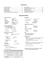
10 ADJUSTMENT 12 TROUBLESHOOTING GUIDE 14 WIRING DIAGRAM 18 EXPLODED VIEW 19 REPLACEMENT PARTS LIST 21 SCHEMATIC DIAGRAM 26 SPECIFICATIONS 1. LCD CHARACTERISTICS Type Size Pixel Pitch Color Depth Electrical Interface Surface Treatment Operating Mode Backlight Unit : TFT WSXGA LCD : 20 - Dell 2005FPW | Service Manual - Page 3
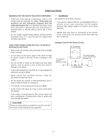
the original parts and labor guarantee. TAKE CARE DURING HANDLING THE LCD MODULE WITH BACKLIGHT UNIT. • Must mount the module using mounting holes arranged in four corners. • Do not press on the panel, edge of the frame strongly or electric shock as this will result in damage to the screen. • Do not - Dell 2005FPW | Service Manual - Page 4
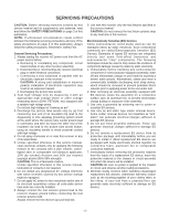
, lubrication of contacts in not required. 6. Do not defeat any plug/socket B+ voltage interlocks with which receivers covered by this service manual might be equipped. 7. Do not apply AC power to this instrument and/or any of its electrical assemblies unless all solid-state device heat sinks are - Dell 2005FPW | Service Manual - Page 5
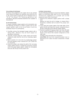
extending from the circuit board and crimp the "U" with long nose pliers to insure metal to metal contact then solder each connection. Power Output, Transistor Device Removal/Replacement 1. Heat and remove all solder from around the transistor leads. 2. Remove the heat sink mounting screw (if so - Dell 2005FPW | Service Manual - Page 6
Use the following technique to repair the defective copper pattern at connections other than IC Pins. This technique involves the installation of a jumper wire on the component side of the circuit board. 1. Remove the defective copper pattern with a sharp knife. Remove at least 1/4 inch of copper - Dell 2005FPW | Service Manual - Page 7
etc... (ms) >> Mode 1 2 3 4 5 6 7 8 H/V Sync Dot Sort Polarity Clock Total Period Video Active Time Frequency (E) (A) H - 48 33 120 16 88 23 160 21 160 29 176 28 256 32 Resolution 720x400 70Hz 640x480 60Hz 640x480 75Hz 800x600 60Hz 800x600 75Hz 1024x768 60Hz 1024x768 75Hz 1152x864 - Dell 2005FPW | Service Manual - Page 8
1) Remove the screws. DISASSEMBLY 2) Please lift central inside edge of Cabinet upward with fingertip then latch will be departed. (This time take cabinet up, power connector lead may be disconnected or damaged.) Refer to the small picture. 6) Turn upside down then lift the back cover ass'y up. - Dell 2005FPW | Service Manual - Page 9
DVI Rx Scaling OSD LVDS Tx Real colour Flash ROM Power 2.5V 3.3V DDR RAM Regulator 3.3V 1.8V 5V Regulator Regulator 3.3V 2.5V Regulator 1.8V 12V 12V Audio supply USB 2040H 5V Up stream Down Stream *2 LVDS 12V (LPL) 5V (AUO) EEPROM (System) 5V Down Stream Down Stream KEY Panel - Dell 2005FPW | Service Manual - Page 10
the two 3.3V and one 2.5V and one 1.8Vregulators to convert power which is provided 12V in Power Board V is provided for LCD Panel.(Only LPL) 5V in Power Board V is provided for LCD Panel.(Only AUO) 12V in Power Board V is provided for Inverter Part. Also, 5V is converted 3.3V and 2.5V and 1.8V by - Dell 2005FPW | Service Manual - Page 11
and a bulk capacitor. 3. Energy Transfer. This part function is for transfer the primary energy to secondary through a power transformer. 4. Output rectifier and filter. This part function is to make a pulse width modulation control and to provide the driver signal to power switch,to adjust the duty - Dell 2005FPW | Service Manual - Page 12
ADJUSTMENT Windows EDID V1.0 User Manual Operating System: MS Windows 98, 2000, XP Port Setup: Windows 98 => Don't need setup Windows 2000, XP => Need to Port Setup. This program is available to LCD Monitor only. 1. Port Setup a) Copy "UserPort.sys" file to "c:\WINNT\system32\drivers" folder b) Run - Dell 2005FPW | Service Manual - Page 13
adjustment and press Menu. If the number change to 2, gain adjustment is ok. b)NVRAM Init : EEPROM initialize(24c16. c)Reset Time : Reset elapsed time. d)Aging : Select Aging mode (On/Off). e)WProtect : To enable write protection.(24c02) f)Blue : Allows you to set the R/G/B - 9300K value manually - Dell 2005FPW | Service Manual - Page 14
TROUBLESHOOTING GUIDE 1. NO POWER NO POWER (POWER INDICATOR OFF) 1 CHECK J101 VOLTAGE PIN6, 7, 9(5V)? YES , U401) NO CHECK POWER BOARD, AND FIND OUT A SHORT POINT AS OPENING EACH POWER LINE NO CHECK 3.3V, 5V LINE (OPEN CHECK) NO CHECK U402 VCC X-TAL, RESET Waveforms 1 J101-#6,7,9(5V - Dell 2005FPW | Service Manual - Page 15
CAUTION LABEL. NO (CONTACT PROBE TO CAUTION LABEL. CAN YOU SEE PULSE AT YOUR SCOPE? YES REPLACE CCFL LAMP IN THE LCD MODULE Waveforms 4 J101-#10(3.3V) 5 J101-#12(3.3V) CHECK LIPS CHECK MICOM INV ON/OFF PORT. 1. CONFIRM BRIGHTNESS OSD CONTRL STATE. 2. CHECK MICOM DIM-ADJ PORT LIPS - 15 - - Dell 2005FPW | Service Manual - Page 16
Q105 PIN3 IS 65.22KHz H- SYNC? Q106 PIN3 IS 60Hz V- SYNC? IS PULSE APPEARED AT SIGNAL PINS? AT MODE 11? YES TROUBLE IN CABLE OR LCD MODULE Waveforms 6 U402-G4, G43(14.318V) 7 Q105-#3 NO TROUBLE IN LIPS NO TROUBLE IN LIPS NO TROUBLE IN LIPS 1. CHECK G4, G3 NO SOLDERING CONDITION 2. CHECK X401 - Dell 2005FPW | Service Manual - Page 17
4. TROUBLE IN DPM TROUBLE IN DPM 9 10 CHECK R135, R137(SYNC) ? YES CHECK R144(SIGNAL DETECT) ? YES TROUBLE IN PC NO CHECK PC PC IS NOT GOING INTO DPM OFF MODE NO TROUBLE IN SIGNAL CABLE Waveforms 9 R135,R137-V-SYNC 10 R135,R137-H-SYNC - 17 - - Dell 2005FPW | Service Manual - Page 18
WIRING DIAGRAM Connector Ass'y P/N: 6631T11020P Connector Ass'y P/N: 6631T12007A Connector Ass'y P/N: 6631T20028G J901 J904 J401 J101 J110 CW401 CW402 CW405 CW406 Connector Ass'y P/N: 6631T11017V - 18 - - Dell 2005FPW | Service Manual - Page 19
- 19 - 010 020 060 070 050 EXPLODED VIEW 240 250 260 090 100 110 080 130 140 160 180 150 190 170 120 040 030 200 210 220 230 - Dell 2005FPW | Service Manual - Page 20
, USB DELL[20.1""] METAL, STAND LOCK DELL 18.1" METAL, FIX VESA LOCK LEFT DELL 18.1"" METAL, FIX VESA LOCK RIGHT DELL 18.1"" SPRING, COIL D4.0 FOR STAND L1801 KNOB, SELF RETURN STAND RELEASE BUTTON DELL 18.1""" SPRING, COIL D5.0 FOR STAND L1801 COVER, LD20FPWM BASE TOP DELL[20.1""] COVER, LD20FPWM - Dell 2005FPW | Service Manual - Page 21
SAFETY PRECAUTIONS IN THIS MANUAL. * NOTE : S SAFETY Mark AL ALTERNATIVE PARTS *S *AL LOC. NO. PART NO. MAIN BOARD CAPACITORS DATE: 2004. 10. 50V 5% R/TP NP0 330PF 1608 50V 5% R/TP NP0 10000PF 50V 10% B(Y5P) 2012 47UF MVK 16V 20% R/TP(SMD) S 0.1UF 50V 10% X7R 2012 R/TP 0.1UF 50V 10% X7R 2012 R/TP - Dell 2005FPW | Service Manual - Page 22
50V 10% X7R 2012 R/TP "100UF KMG,RD 16V 20% FM2.5 T" 0.01UF 1608 50V 10% R/TP B(Y *S *AL LOC. NO. PART NO. DATE: 2004. 10. 05. DESCRIPTION / KMG 25V M FL TP 5 0.1UF 1608 50V 10% R/TP X7R "1UF 1608 16V 80%,-20% R/TP F" 1000PF 1608 50V 0.1 R/TP X7R RJ4-25V101MX ELNA 25V 100UF 0.1UF 50V 10 - Dell 2005FPW | Service Manual - Page 23
100P,LQFP T" "HY5DU283222AQ-4 HYNIX 100P,L" GM1501-CF(ESD ENHANCEMENT)DE "DELL 20.1"" LD20FPWM MICOM" S524A60X51(SCT0) SAMSUNG ELE KIA7042AP TO-92 TP 4.2 600JT CERATEC R/TP HH-1M2012-600JT CERATEC R/TP *S *AL LOC. NO. PART NO. DATE: 2004. 10. 05. DESCRIPTION / SPECIFICATION L607 L615 L616 L617 - Dell 2005FPW | Service Manual - Page 24
% D 10K OHM 1/10 W 1% 2012 R/TP 10K OHM 1/10 W 1% 2012 R/TP 150 1/10W 5 D.R/TP 100 OHM 1/10 W 5% 1608 R/TP 0 OHM 1 / 10 W 2012 5.00% D *S *AL LOC. NO. PART NO. DATE: 2004. 10. 05. DESCRIPTION / SPECIFICATION R409 R410 R411 R412 R413 R414 R415 R418 R419 R420 R421 R422 R423 R424 R426 R427 R428 R430 - Dell 2005FPW | Service Manual - Page 25
"KJA-DN-0-0022 KSD S-VHS,4P,R" *S *AL LOC. NO. PART NO. DATE: 2004. 10. 05. DESCRIPTION / SPECIFICATION J601 X202 X401 12V 50 SKQGACE010 J-ALPS NON 12V 50 USB BOARD C901 C902 C903 C904 C905 C906 C907 C908 D901 0DZ560009GB 0DZ560009GB 100UF MVK 16V 20% R/TP(SMD) 100UF MVK 16V 20% R/TP(SMD) 0.1UF - Dell 2005FPW | Service Manual - Page 26
SCHEMATIC DIAGRAM 1. CONNECTOR & JACK - 26 - 1 J101-#6,7,9(5V) 4 J101-#10(3.3V) 5 J101-#12(3.3V) 1 4 5 79 8 10 7 9 Q105-#3, R135,R137-V-SYNC 8 10 Q106-#3, R135,R137-H-SYNC - Dell 2005FPW | Service Manual - Page 27
2. TW9905 - 27 - - Dell 2005FPW | Service Manual - Page 28
6 3 3. SCALLER(GM1601) - 28 - 2 U403-#32(3.3V) 2 3 U401, R435, R436-#3, 4 6 U402-G4, G43(14.318V) - Dell 2005FPW | Service Manual - Page 29
4. POWER/CONNECTOR - 29 - - Dell 2005FPW | Service Manual - Page 30
5. USB HUB - 30 - - Dell 2005FPW | Service Manual - Page 31
6. KEY - 31 - - Dell 2005FPW | Service Manual - Page 32
7. USB - 32 - - Dell 2005FPW | Service Manual - Page 33
P/NO : 3828TSO058N Oct. 2004 Printed in Korea
-
 1
1 -
 2
2 -
 3
3 -
 4
4 -
 5
5 -
 6
6 -
 7
7 -
8
-
9
-
10
-
11
-
12
-
13
-
14
-
15
-
16
-
17
-
18
-
19
-
20
-
21
-
22
-
23
-
24
-
25
-
26
-
27
-
28
-
29
-
30
-
31
-
32
-
33
 |
 |

COLOR MONITOR
SERVICE MANUAL
CAUTION
BEFORE SERVICING THE UNIT,
READ THE
SAFETY PRECAUTIONS
IN THIS MANUAL.
CHASSIS NO. : CL-74
MODEL: 2005FPW