Dell 2330 Service Manual
Dell 2330 Manual
 |
UPC - 807027103130
View all Dell 2330 manuals
Add to My Manuals
Save this manual to your list of manuals |
Dell 2330 manual content summary:
- Dell 2330 | Service Manual - Page 1
Dell 2330d/dn Service Manual 11 Dec 2008 - Dell 2330 | Service Manual - Page 2
Inc. All rights reserved. Reproduction in any manner whatsoever without the written permission of Dell Inc.is strictly forbidden. Trademarks used in this text: Dell and the DELL logo are trademarks of Dell Inc. Other trademarks and trade names may be used in this document to refer to the entities - Dell 2330 | Service Manual - Page 3
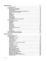
of the operator panel and menus 2-2 Indicator light 2-2 Buttons 2-3 Diagram of the printer menus 2-5 Messages and error codes 2-6 User attendance messages 2-6 Cartridge error messages 2-9 Paper jam error codes (200-series 2-9 Service error codes 2-15 Symptom tables 2-20 POST symptom table - Dell 2330 | Service Manual - Page 4
3-1 Printing menus 3-1 Configuration menu (CONFIG MENU 3-2 Entering Configuration Menu 3-2 Available menus 3-2 Reset photoconductor maintenance counter (Reset PC Cnt 3-3 Print quality pages (Prt Quality Pgs 3-3 Reports 3-3 Panel Menus 3-3 PPDS Emulation 3-3 Demo Mode 3-4 Factory Defaults - Dell 2330 | Service Manual - Page 5
Operator panel removal 4-51 Paper input and duplex sensor assembly removal 4-52 Printhead removal 4-53 Rear door and rear cover removal 4-54 Rear exit guide assembly with sensor and reversing solenoid removal 4-56 Right side cover assembly removal 4-58 Toner level sensor removal 4-60 Top - Dell 2330 | Service Manual - Page 6
vi - Dell 2330 | Service Manual - Page 7
in the wavelength region of 655-675 nanometers. The laser system and printer are designed so there is never any human access to laser radiation above a Class I level during normal operation, user maintenance, or prescribed service condition. Laser Der Drucker erfüllt gemäß amtlicher Bestätigung der - Dell 2330 | Service Manual - Page 8
Subchapter J, voor andere landen in IEC 60825-1. Laserprodukten van klasse I worden niet als ongevaarlijk aangemerkt. De printer is voorzien van een laser van klasse IIIb (3b), dat wil zeggen een gallium arsenide-laser van 7 milliwatt met een golflengte van 655-675 nanometer. Het lasergedeelte en de - Dell 2330 | Service Manual - Page 9
utsätts för laserstrålning över Klass I-nivå vid normal användning, underhåll som utförs av användaren eller annan föreskriven serviceåtgärd. Laser-melding Skriveren er godkjent i USA etter kravene i DHHS 21 CFR, underkapittel J, for klasse I (1) laserprodukter, og er i andre land godkjent som et - Dell 2330 | Service Manual - Page 10
Avís sobre el Làser Segons ha estat certificat als Estats Units, aquesta impressora compleix els requisits de DHHS 21 CFR, apartat J, pels productes làser de classe I (1), i segons ha estat certificat en altres llocs, és un producte làser de classe I que compleix els requisits d'IEC 60825-1. Els - Dell 2330 | Service Manual - Page 11
Notices and safety information xi - Dell 2330 | Service Manual - Page 12
xii - Dell 2330 | Service Manual - Page 13
of use of unauthorized replacement parts. • The maintenance information for this product has been prepared for use by a professional service person and is not per la sicurezza in caso di sostituzione non autorizzata delle parti. • Le informazioni riguardanti la manutenzione di questo - Dell 2330 | Service Manual - Page 14
El personal cualificado debe ser consciente de este peligro y tomar las precauciones necesarias. • PRECAUCIÓN: este símbolo indica que el voltaje de la parte del equipo con la que está trabajando es peligroso. Antes de empezar, desenchufe el equipo o tenga cuidado si, para trabajar con él, debe - Dell 2330 | Service Manual - Page 15
producte. El personal professional ha d'estar-ne assabentat i prendre les mesures convenients. • PRECAUCIÓ: aquest símbol indica que el voltatge de la part de l'equip amb la qual esteu treballant és perillós. Abans de començar, desendolleu l'equip o extremeu les precaucions si, per treballar - Dell 2330 | Service Manual - Page 16
, symptom tables, and service checks used to isolate failing field replaceable units (FRUs). 3. Diagnostic aids contains tests and checks used to locate or repeat symptoms of printer problems. 4. Repair information provides instructions for making printer adjustments and removing and installing FRUs - Dell 2330 | Service Manual - Page 17
The Dell 2330d and Dell 2330dn are monochrome laser printers designed for single users or small workgroups. Maintenance approach The diagnostic information in this manual leads to the correct field replaceable unit (FRU) or part. Use the error code charts, symptom index, and service checks - Dell 2330 | Service Manual - Page 18
Overview of the operator panel The operator panel consists of these items: • A 2-line liquid crystal display (LCD) that shows text • Six buttons: Menus , Back ,Navigation (with Left Menu Stop • An indicator light , Select and Right Menu ), and Menus Back Stop 1-2 - Dell 2330 | Service Manual - Page 19
/option card 2¹ ¹ Only one slot is active for 64MB flash memory or font card. Print quality settings Dell 2330dn 32MB 288MB ✔ ✔ x ✔ x ✔ 1 2¹ Item Dell 2330d Dell 2330dn Print resolution 1200 Image quality¹ ✔ ✔ 2400 Image quality² ✔ ✔ 600 X 600 dpi ✔ ✔ 1200 X 1200 dpi³ ✔ ✔ ¹ 1200 - Dell 2330 | Service Manual - Page 20
Item Dell 2330d Dell 2330dn Data stream emulations Host based printing ✔ ✔ PCL 5e and PCL 6 ✔ ✔ PostScript 3 ✔ ✔ PPDS migration tool ✔ ✔ PDF v1.6 x x XPS¹ x x HTML (including DBCS) x x Direct image x x Compatibility Windows/Macintosh/Linux Windows/Macintosh - Dell 2330 | Service Manual - Page 21
input trays Integrated 250-sheet tray 50-sheet MP feeder 1-sheet manual feed slot Dell 2330d ✔ ✔ x Dell 2330dn ✔ ✔ x Optional input sources 250-sheet drawer ✔ ✔ 550-sheet drawer ✔ ✔ Maximum input sheet capacity 850 (excluding envelopes) 850 (excluding envelopes) Manual/integrated print - Dell 2330 | Service Manual - Page 22
Types of print media Note: Ensure trays are properly loaded. Never mix media types within a tray. Source Sizes Types Weight Input capacity* (sheets) Input tray 1 (250-sheet tray) A4, A5, A6,JIS¹-B5, letter, legal, executive, oficio (Mexico)², folio², statement Plain paper, recycled, labels, - Dell 2330 | Service Manual - Page 23
on preventing jams Paper path I J F G E H K L C B D M A A Paper path B Manual feed sensor C Upper end feed rolls D Input sensor E Transfer roll F Fuser G Fuser exit rolls H Fuser exit sensor I Exit rolls J Exit sensor K Duplex unit L Duplex sensor M Auto compensator - Dell 2330 | Service Manual - Page 24
below the maximum media fill indicators on the 250-sheet tray before pushing the tray into the printer. • Make sure paper guides are positioned before loading the paper or specialty media. • Do not remove trays while a job is printing. • Before loading transparencies, fan the stack to prevent sheets - Dell 2330 | Service Manual - Page 25
cartridge/photoconductor system) Dual In-Line Memory Module External Network Adapter Field Replaceable Unit Host Based Printing High Voltage Power Supply Liquid Crystal Diode Light Emitting Diode Laser Scanning Unit Low Voltage Power Supply Nonvolatile Random Access Memory Photoconductor Printer - Dell 2330 | Service Manual - Page 26
1-10 - Dell 2330 | Service Manual - Page 27
Busy is displayed. 6. Close Door will be displayed if the cover is open. 7. Any cartridge errors, such as Defective Cartridge, are displayed. 8. Applicable maintenance messages are displayed. 9. Applicable toner low messages are displayed. 10. The printer displays Ready. Diagnostics information 2-1 - Dell 2330 | Service Manual - Page 28
LCD display Menus Indicator light Back Stop Back button Left arrow button Select Right arrow Stop button button button Indicator light The indicator light gives information about the status of the printer. If the light is Off On Blinking The printer is Off On, but idle On and busy - Dell 2330 | Service Manual - Page 29
or override the user default settings selected from the operator panel. • Press once to return to the previous display screen while in the menus. • Press twice to exit the menus and return to the Ready state. • Press to stop printer activity. • Press to cancel a print job. Stopping will - Dell 2330 | Service Manual - Page 30
describing the current state of the printer and indicating possible printer problems that must be resolved. The top line of the display is the header line. It will display the current status and the Supplies (Warnings) status. This is where printer status, supplies messages, and show-me screens are - Dell 2330 | Service Manual - Page 31
Demo Print Menus Print Stats Print Net Setup Print Fonts Print Demo Factory Defaults Hex Trace Setup Menu Eco-Mode Quiet Mode Printer Language Power Saver Resource Save Print Timeout Wait Timeout Auto Continue Jam Recovery Page Protect Print area Display Language Toner Alarm Job Menu Reset Printer - Dell 2330 | Service Manual - Page 32
cancel the print job. Wait for the message to clear. The printer has detected an unsupported refilled cartridge. Remove the indicated print cartridge, and install a new one. Close the specified door to clear the message. Wait for the message to clear. Warning: Do not turn the printer off while this - Dell 2330 | Service Manual - Page 33
a tray with the correct media type and size, then it prints on whatever media is installed in the default input source. • Cancel the current job. • Load the input source with the correct type and size media. • Cancel the current job. Replace the maintenance items and, if necessary, reset the printer - Dell 2330 | Service Manual - Page 34
the factory default except: - The Display Language setting in the Setup Menu - All settings in the Parallel Menu, Network Menu, and USB Menu The standard bin is full. • Replace the toner cartridge. • Press to clear the message and continue printing. Insert the tray into the printer. The printer is - Dell 2330 | Service Manual - Page 35
specified length. Error Description Action 200.00 Paper jam around input sensor. Remove the PC kit and paper or debris at the input sensor. 200.01 200.02 Classic input jam. The media is too long over the input sensor. Possible causes include multi-sheet feed, tray size sensing problem, and - Dell 2330 | Service Manual - Page 36
bouncy manual feed sensor. Remove the toner cartridge/PC kit. At the front, remove the upper front guide, and inspect the flag on the manual input sensor. If the flag is loose, then replace it. See "Media manual input sensor removal" on page 4-39. 200.15 UNRECOVERABLE NO GAP JAM. Engine detected - Dell 2330 | Service Manual - Page 37
to go beyond the wear strips. 201.00 Paper jam between input and exit sensor Remove the toner cartridge/PC kit and check for obstructions between the input sensor and the fuser. if the media continues to stop at the entrance or in the fuser, then replace the fuser. See "Fuser removal" on page 4-20 - Dell 2330 | Service Manual - Page 38
feeding out the media that was detected during warm-up. 201.26 Page at fuser nip before fuser started ramping toward desired temperature. Indicates code may be receiving more interrupts than intended Remove the toner cartridge/PC kit and check for obstructions between the input sensor and the fuser - Dell 2330 | Service Manual - Page 39
open the gap by stopping the feed rolls, trailing edge was seen at the input sensor, manual feeder sensor is no longer covered. 241.19 Second pick attempted failed from Tray 1, no pages printed since calling a 241.10 or a prior 241.19. 242.00 Paper jam near tray 2. Remove Tray 2 and inspect for - Dell 2330 | Service Manual - Page 40
to feed from tray 2. Pages in the paper path have been flushed to the output bin. Remove Tray 2 and inspect for obstruction in the paper path. Check the pick tires for wear or paper dust. Replace if necessary. Check the wear strips and replace if necessary. 251.00 251.10 251.11 Paper jam near - Dell 2330 | Service Manual - Page 41
on page 2-37. Fuser service errors 920.00 920.01 Under temperature during steady state control. Fuser took too long to heat up after transitioning to new enhanced mode. Replace the fuser. See "Fuser service check" on page 2-25. 920.02 Fuser fell too far below desired temperature while printing - Dell 2330 | Service Manual - Page 42
. Toner service errors 929.00 929.01 929.02 Toner sensor error No home window No sensor transition (closed) Remove the toner cartridge, and shake it Try a different toner cartridge, if possible. If the error persists, then replace the toner level sensor. See "Toner level sensor removal" on page - Dell 2330 | Service Manual - Page 43
motor service errors 936.01 No lock detected at normal motor start 936.02 No lock detected at motor start for motor ID 936.03 No halls detected at motor start 936.04 Failed to stop within timeout 936.05 Stall detected during speed control Replace the printhead. See "Printhead service check" on page - Dell 2330 | Service Manual - Page 44
Firmware or controller board errors 959.01 959.02 Controller verification failure of pensive boot code Failure to authenticate Signature Verification Code Call the next level of support to update the firmware, or replace the controller board. See "Controller board service check" on page - Dell 2330 | Service Manual - Page 45
memory configuration Memory and emulation errors 960.xx RAM memory error: RAM soldered on the controller board is bad Replace the controller board. See "Controller board service check" on page 2-22. 961.xx RAM memory error: memory card in slot is bad. Replace the memory card. 964.xx Download - Dell 2330 | Service Manual - Page 46
page 2-26. See "Cooling fan service check" on page 2-23. See "Fuser service check" on page 2-25. See "Fuser service check" on page 2-25. See "Paper feed service checks" on page 2-27. Note: Investigate any displayed codes before proceeding with these symptoms. For example, a missing toner cartridge - Dell 2330 | Service Manual - Page 47
sides of media • Toner not fused • Streaks • Blank pages Action See "Cooling fan service check" on page 2-23. See "LVPS/HVPS service check" on page 2-25. See"Fuser service check" on page 2-25 or "Solving print quality problems" on page 2-34. See "Paper feed service checks" on page 2-27. See "Main - Dell 2330 | Service Manual - Page 48
at CN201.Verify continuity in each conductor of the cable. This cable is not a replaceable part. If continuity is still not good then go to "Dead machine service check" on page 3-24. Controller board voltage outputs Turn the printer off, and plug the LVPS/HVPS cable into J502 of the controller board - Dell 2330 | Service Manual - Page 49
V dc as well. If it is close to 24 V dc while the fan is still idle, then replace the fan. See "Fan removal" on page 4-16. Cover interlock switch service check Note: Make sure a print cartridge assembly is installed and the cover closes all the way, engaging the cover open switch lever. FRU Cover - Dell 2330 | Service Manual - Page 50
power supply: Pins Voltage CN201-6, 17, +24 V dc 19 CN201-10, 12, Ground 14, 16, 18 CN201-1,3, 5, +5 V dc 11,13, 15 • If voltages are not correct, then replace the LVPS/HVPS. • If voltages are correct, then check the controller board. See "Controller board service check" on page 2-22. 2-24 - Dell 2330 | Service Manual - Page 51
. See "LVPS/HVPS service check" on page 2-25. • If there is no continuity, then disconnect the fuser power cable at both ends and check each conductor for continuity. Replace cable if necessary. • If the cable tests good, then replace the fuser. Reconnect the cables, turn the printer on, and at &12 - Dell 2330 | Service Manual - Page 52
Main motor service check FRU Main motor gear drive Main motor cable LVPS/HVPS Controller board Warning: Do not replace the operator panel and controller board at the same time. Each card contains the printer settings. When either of these cards is new, it obtains the settings from the other card. - Dell 2330 | Service Manual - Page 53
" on page 2-22. Buttons If the buttons do not respond, then replace the operator panel. There is no test or repair for the faulty switches on the operator panel. Paper feed service checks Paper jam error indication during POST FRU Fuser (exit sensor) Input/duplex sensor Manual feed sensor Action - Dell 2330 | Service Manual - Page 54
. Pin 1 at J26 should be +24 V dc. See "Controller board service check" on page 2-22 for more information. Replace controller board as necessary. Media skews FRU Paper feed (pick tires) tray 1 Paper feed (pick tires) tray 2 Tray 1 Tray 2 (option) Action Check tires for debris. If tires are new - Dell 2330 | Service Manual - Page 55
stacking, or curl. Print the menu sheet found under Utilities. Look at the media settings. Some, such as card stock or rough texture, may require a higher fuser temperature, which leads to more of these problems (except stacking) in plain paper. • Change settings using the printer driver. • Use the - Dell 2330 | Service Manual - Page 56
of the transfer roll gear. • If there is not continuity, then call the next level of service. Try a different toner cartridge and PC kit. • If those fail, then replace the LVPS/HVPS, controller board, or the printhead in that order. Also, see "Solving print quality problems" on page 2-34. 2-30 - Dell 2330 | Service Manual - Page 57
service check" on page 2-25 and the "Controller board service check" on page 2-22, if necessary. Heavy background Poor development or poorly charged toner particles cause excessive background. This is more noticeable as the toner cartridge nears end-of-life. FRU Toner cartridge (not a FRU) PC Kit - Dell 2330 | Service Manual - Page 58
the laser light path is not blocked. If toner cartridge is low, then try a new one. Make sure recommended media is being used. Check the media settings in the printer driver. A heavier media may require higher heat to properly fuse. Variation in image density horizontally across page FRU PC Kit - Dell 2330 | Service Manual - Page 59
. Inspect the toner cartridge and paper feed components, especially the drive coupler and drive gears for debris, binds, or damage. Toner on back of page FRU Photoconductor kit (not a FRU) Fuser Transfer roll HVPS or controller board Action Print a menu page found under Utilities, and check - Dell 2330 | Service Manual - Page 60
horizontal streaks appear on the page Vertical streaks Something could be caught between the PC kit and the fuser. Check the paper path around the fuser entry. Try a different toner cartridge. Vertical white lines may be caused by the laser beam, which may be partially blocked. With the printer off - Dell 2330 | Service Manual - Page 61
setting from the printer driver. • Try a different type of paper. Media designed for copiers gives the best quality. • Replace the toner cartridge. • The print cartridge may be out of toner or defective. Replace the cartridge. • There may be a software error. Re-initialize the printer by turning it - Dell 2330 | Service Manual - Page 62
Tray 2. The printer does not print after a paper jam has been cleared. Cause / action • Make sure the parallel or USB cable is not damaged and is firmly plugged into the connector on the back of the printer. • Make sure the toner cartridge assembly is installed properly. • Print the menu page - Dell 2330 | Service Manual - Page 63
not printing, and an error message is displayed. While in PostScript 3 emulation, the printer is flushing data (an error message is displayed). Cause / action • Ensure correct printer driver is being used. • Select hex trace mode to determine what the problem is. • Restore factory defaults. • Make - Dell 2330 | Service Manual - Page 64
of the service manual, or "Controller board connector pin values" on page 3-2 for the J28 connector. Pins 1, 4: 3.3 V Pin 2: 24 V Pin 6: Ground If the voltages are incorrent, then replace the controller board. If the voltages are correct, then try using Tray 2 again. If the printer error persists - Dell 2330 | Service Manual - Page 65
that can be accessed during POR to identify problems with the printer. Configuration Menu Diagnostics Mode 1. Turn off the printer. 2. Press and hold and . 3. Turn on the printer. 4. Release the buttons when Performing Self Test displays. 5. The message CONFIG MENU displays on the top line of - Dell 2330 | Service Manual - Page 66
Exit Configuration Menu See "Reset photoconductor maintenance counter (Reset PC Cnt)" on page 3-3. See "Print quality pages (Prt Quality Pgs)" on page 3-3. See "Reports" on page 3-3. See "Panel Menus" on page 3-3. See "PPDS Emulation" on page 3-3. See "Demo Mode" on page 3-4. See "Factory Defaults - Dell 2330 | Service Manual - Page 67
photoconductor maintenance counter (Reset PC Cnt) The reset photoconductor maintenance counter resets the photoconductor kit page counter and clears any warnings or photoconductor exhausted messages. This operation should be performed only after a new photoconductor unit has been installed. Print - Dell 2330 | Service Manual - Page 68
. Note: While Demo Mode is set to On, only demonstration files can print. Files received across the network or from the host computer are ignored. Factory Defaults This setting enables a user to restore all the printer settings to the original factory settings. The selections are Do not restore - Dell 2330 | Service Manual - Page 69
See "Registration" on page 3-6. See "Print tests" on page 3-7. See "Hardware tests" on page 3-8. See "Duplex tests" on page 3-9. See "Input tray tests" on page 3-10. See "Output bin tests" on page 3-11. See "Base sensor test (B. sensor test)" on page 3-11. See "Printer setup" on page 3-12. See "EP - Dell 2330 | Service Manual - Page 70
top margin. The default margin is 1/6 inch. Note: Modifying the top margin moves the entire image either up or down on the physical page. In order to preserve the bottom margin, changing the top margin does not compress or expand the image. Bottom Margin This setting moves the black plane's bottom - Dell 2330 | Service Manual - Page 71
the selected input and prints a test page on it. No buttons are active during the Single test. The Continuous test feeds media from the selected input and prints test pages until is pressed. The printer always generates a simplexed version of the Print Test page in its default resolution. While - Dell 2330 | Service Manual - Page 72
Button Test • DRAM Test Press or to scroll through the Hardware Tests menu, and then press LCD Test to select the desired test. Once the LCD Test setting is selected, the printer memory test has failed and finished with errors. fails, then the message DRAM Error displays for approximately three seconds - Dell 2330 | Service Manual - Page 73
diamonds at the top and bottom • Horizontal lines to check for skew • General printer information, including current page count, installed memory, serial number, and code level. To print the duplexed Quick Test page: 1. Select Quick Test from the DUPLEX TESTS menu. 2. Select Single or Continuous by - Dell 2330 | Service Manual - Page 74
display: Duplex Feed 1 Clear Paper... 3. Remove the blank page from the printer, and press to return to the DUPLEX TESTS menu. Input tray tests The INPUT TRAY TESTS setting is used to test the printer's installed input trays and their sensors. Feed Tests The Feed Test observes the paper path of - Dell 2330 | Service Manual - Page 75
bins and its sensors. Feed Tests This test verifies that the media from the printer's default input source feeds to the specific output bin. Press to select Single, or press and to select Continuous. The Single test feeds one sheet of media to the default output bin. No buttons are active during - Dell 2330 | Service Manual - Page 76
value of this setting determines whether the printer uses the U.S. or Non-U.S. factory default value for the settings listed below: Device Setting Paper sizes Envelope size PCL Symbol Set PPDS Code Page Universal Units of Measure U.S. value Letter 10 PC-8 437 Inches Non-U.S. value A4 DL Envelope - Dell 2330 | Service Manual - Page 77
Select Service Tag from the PRINTER SETUP menu. 2. Press Back to return to PRINTER SETUP. Engine Setting 1 through 4 Warning: Do not change these settings unless requested to do so by your next level of support. Model Name The serial number can only be viewed and cannot be changed. Configuration ID - Dell 2330 | Service Manual - Page 78
in consecutive positions in the log are entered. All 2xx and 9xx error messages are stored in the event log as well as the PC kit and maintenance counter resets and NVRAM resets initiated by the Factory Defaults setting in the UTILITIES menu. To view the display log: 1. Select Display Log from the - Dell 2330 | Service Manual - Page 79
printer information, including model and serial number • Time and date stamps • Page counts for each error The printed error log can be faxed to Dell or your next level of support for verification or diagnosis. This report can also be printed from the Configuration Menu. Because you can clear error - Dell 2330 | Service Manual - Page 80
press . 7. Print the Quick Test page again and check that the darkest line in the center graph is equal to zero. If it is, then check to see if the left, top, and bottom margins are detected. If it is not, then repeat step 5. Note: The alignment of the left margin positions the black - Dell 2330 | Service Manual - Page 81
) for wear, the paper path for obstructions, the fuser for proper setting, and the tray paper guides for fit to the media. Paper feed skew Printhead misalignment To adjust the printhead: 1. Enter the Diagnostics Menu. See "Entering Diagnostics menu" on page 3-5. 2. Select PRINT TESTS. 3. Select - Dell 2330 | Service Manual - Page 82
corresponding lines on the left flap, then adjust the printhead clockwise relative to the printer and recheck. (See the left side of the figure below.) If the grid of the figure below.) 8. After obtaining a properly adjusted image on the paper, tighten all three screws. Note: The printhead must be - Dell 2330 | Service Manual - Page 83
4. Repair information Warning: Read the following before handling electronic parts. Handling ESD-sensitive parts Many electronic products use parts that are known to be sensitive to electrostatic discharge (ESD). To prevent damage to ESD-sensitive parts, follow the instructions below in addition to - Dell 2330 | Service Manual - Page 84
cables from the printer to prevent damage during service. • Unless otherwise stated, reinstall the parts in reverse order of removal. • When reinstalling a part held with several screws, start all screws before final tightening. • Remove the paper tray and print cartridge before proceeding with - Dell 2330 | Service Manual - Page 85
the ACM pick tires. Warning: Open the duplex door only far enough to remove the ACM pick tires. If the door is opened too far, then it can become disengaged and interfere with the paper tray. The tray may go in but will not come out, and will render the printer as non-serviceable. 3. After the ACM - Dell 2330 | Service Manual - Page 86
pick tire roller (A). Note: • If the left hub is gray, then disconnect the old right and left tire/hub assemblies from the ACM, and replace with the new right and left tire/hub assemblies. • If the left hub is black, then remove the old right and left tires from the ACM hubs, and replace with - Dell 2330 | Service Manual - Page 87
Bezel removal 1. Open the front access door. 2. Flex the top of the bezel, and disconnect the latch (A) from the upper front cover. 3. Disconnect the latches (B) from the upper front cover. 4. Remove the bezel. Repair information 4-5 - Dell 2330 | Service Manual - Page 88
the printer settings. When either of these cards is new, it obtains its settings from the other card. Critical factory settings are lost when both cards are new and are replaced at the same time. 1. Remove the right side cover. See "Right side cover assembly removal" on page 4-58. 2. Remove the - Dell 2330 | Service Manual - Page 89
to access to the controller board. B 4. Remove the five screws (C) from the controller board. C 5. Lift the controller board, and remove. Note: When installing the controller board, place the USB port and parallel port screws first, and then place the controller board screws. Repair information 4-7 - Dell 2330 | Service Manual - Page 90
Cover open sensor 1. Remove the right side cover. See "Right side cover assembly removal" on page 4-58. 2. Disconnect the cable (A) from the controller board. 3. Use a #1 Phillips screwdriver to remove the screw (B) holding the sensor. B A 4. Remove the cover open sensor. 4-8 - Dell 2330 | Service Manual - Page 91
"Left side cover removal" on page 4-23 4. Remove the right side cover. See "Right side cover assembly removal" on page 4-58. 5. Disconnect the operator panel cable (A). 6. Remove the cable through the opening. 7. Remove the three screws (B) from the right side of the printer. Repair information 4-9 - Dell 2330 | Service Manual - Page 92
8. Disconnect the fuser link (C). C 9. Remove the three screws (D) from the left side of the printer. 10. Remove the door mounts. 4-10 - Dell 2330 | Service Manual - Page 93
Duplex removal 1. Remove the right side cover. See "Right side cover assembly removal" on page 4-58. 2. Remove the LVPS/HVPS. See "LVPS/HVPS removal" on page 4-27. 3. Remove the three screws (A) from the shield. A 4. Remove the four screws (B) from the duplex. B Repair information 4-11 - Dell 2330 | Service Manual - Page 94
5. Lift the duplex slightly, push to the left, and tilt to clear the right side of the printer. 6. Remove the duplex. 4-12 - Dell 2330 | Service Manual - Page 95
1. Remove the LVPS/HVPS. See "LVPS/HVPS removal" on page 4-27. 2. Remove the duplex. See "Duplex removal" on page 4-11. 3. Remove the main motor gear drive. See "Main motor gear drive removal" on page 4-30. 4. Remove the e-clip (A) from the gear. 5. Remove the gear (B) and gear shaft (C). Repair - Dell 2330 | Service Manual - Page 96
6. Remove the screw (D) from the gear (E). 7. Remove the plastic bushing (F). 4-14 - Dell 2330 | Service Manual - Page 97
8. Use a screwdriver to loosen the retainer clip (G) from the gear. 9. Remove the gear (H). Repair information 4-15 - Dell 2330 | Service Manual - Page 98
Fan removal 1. Remove the right side cover. See "Right side cover assembly removal" on page 4-58. 2. Disconnect the cable (A) from the controller board, and remove the two screws (B) holding the fan to the right side frame. B 3. Remove the fan. A B 4-16 - Dell 2330 | Service Manual - Page 99
side cover removal" on page 4-23. 3. Remove the upper front guide assembly. See "Upper front guide assembly removal" on page 4-64, steps 1-3. 4. Close the front access door. 5. While closing the MPF cover, pull up on the MPF by the steel shaft until the MPF lifts from its hinges. Repair information - Dell 2330 | Service Manual - Page 100
6. Disconnect the MPF from the lower front cover. 7. Disconnect the fuser link (A) from the front access door. A 4-18 - Dell 2330 | Service Manual - Page 101
8. Disconnect the front access door cable (B), and pull it through the opening to clear the side frame. B 9. Disconnect the front access door from its hinges, and remove. Repair information 4-19 - Dell 2330 | Service Manual - Page 102
Fuser removal 1. Remove the rear exit guide. See "Rear exit guide assembly with sensor and reversing solenoid removal" on page 4-56. 2. Remove the two screws (A). 3. Partially pull the fuser forward for better access. 4. Push in on the cable connector cover (B), and remove. 4-20 - Dell 2330 | Service Manual - Page 103
5. Disconnect the AC cable (C). C B 6. Disconnect the thermistor cable (D). D Repair information 4-21 - Dell 2330 | Service Manual - Page 104
7. Disconnect the exit sensor cable (E) from the controller board. E 8. Remove the fuser. Note: • Be careful to not damage the gears during the fuser installation. • Be sure to reinstall the AC cable during the fuser installation. 4-22 - Dell 2330 | Service Manual - Page 105
the left side cover. • Make sure that the fuser cables are out of the way when removing the left side cover. 1. Remove the paper tray. 2. Remove the screw (A) from the rear left side of the printer. A 3. Remove the screw (B), and press the two latches (C) on the bottom of the left side cover - Dell 2330 | Service Manual - Page 106
4. Swing the cover open, and lift to remove the left side cover. Note: There are two tabs on the top of the left side cover. Do not swing the left side cover open too far, or the tabs will be damaged. 4-24 - Dell 2330 | Service Manual - Page 107
front cover. Note: The picture below shows the E260d, E260dn printer. The lower front cover removal is the same for all remove the front access door, and remove the three screws from the right door mount. See "Front access door removal" on page 4-17 and "Door mount removal" on page 4-9. Repair - Dell 2330 | Service Manual - Page 108
Installation note: Use a flathead screw driver to press in on the door mount (B) while pulling on the front access door to connect the cover to the hinge (C). C B 4-26 - Dell 2330 | Service Manual - Page 109
Remove the left side cover. See "Left side cover removal" on page 4-23. 3. Place the printer on its top with the rear facing you. Note: Be careful to not mar the finish of the printer. 4. Remove the two screws (A) from the right rear foot assembly. A 5. Disconnect the fuser power cable (B). B Repair - Dell 2330 | Service Manual - Page 110
6. Remove the two screws (C) from the right rear foot, and the four screws (D) from the LVPS/HVPS shield. D C 7. Lift the LVPS/HVPS, and disconnect the three cables (E). E 4-28 - Dell 2330 | Service Manual - Page 111
Note: Squeeze the clip to remove the cables from their connectors (F). F 8. Disconnect the transfer roll cable (G). G 9. Lift and remove the LVPS/HVPS. Repair information 4-29 - Dell 2330 | Service Manual - Page 112
Main motor gear drive removal 1. Remove the left side cover. See "Left side cover removal" on page 4-23. 2. Disconnect the fuser link (A) from the front access door. A 3. Place the printer on its right side. Note: Be careful to not mar the finish of the printer. 4. Remove the four screws (B) from - Dell 2330 | Service Manual - Page 113
5. Lift the gear drive, and disconnect the main motor gear drive cable (C). 6. Remove the main motor gear drive. Repair information 4-31 - Dell 2330 | Service Manual - Page 114
Manual feed clutch removal 1. Remove the left side cover. See "Left side cover removal" on page 4-23. 2. Open the front access door, and disconnect the fuser link (A). A 3. Place the printer on its right side. Note: Be careful to not mar the finish of the printer. 4. Remove the four screws (B) from - Dell 2330 | Service Manual - Page 115
6. Use a screwdriver to remove the e-clip (C) from the manual feed clutch. Note: The picture below shows the E260d, E260dn printer. The manual feed clutch removal is the same for all models. C 7. Remove the manual feed clutch (D). D Repair information 4-33 - Dell 2330 | Service Manual - Page 116
" on page 4-11. 3. Open the front access door, and place the printer on its right side. Note: Be careful to not mar the finish of the printer. 4. Remove the two screws (A). Note: The picture below shows the E260d, E260dn printer. The manual feed solenoid removal is the same for all models. A 4-34 - Dell 2330 | Service Manual - Page 117
5. Remove the three screws (B) from the left door mount. B Repair information 4-35 - Dell 2330 | Service Manual - Page 118
on it's top. Note: Be careful to not mar the finish of the printer. 8. Disconnect the cable (D) from J25 on the controller board, and remove the manual feed solenoid. Installation note: Install the two screws holding the new solenoid in place, and route the cable (D) behind the MPF clutch (E). DE - Dell 2330 | Service Manual - Page 119
gear drive removal" on page 4-30. 5. Remove the media feed clutch. See "Media feed clutch with cable removal" on page 4-40. 6. Use a screwdriver to pop the shaft retainer tab (A) loose from the ACM feed shaft. 7. Use a small pair of pliers to remove the shaft retainer tab. Repair information 4-37 - Dell 2330 | Service Manual - Page 120
8. Use a screwdriver to pop the inner shaft lock (B) loose. 9. Remove the inner shaft lock (C). 4-38 - Dell 2330 | Service Manual - Page 121
10. Pull out the auto compensator shaft, and remove the spring (D). 11. Remove the auto compensator shaft. 12. Disconnect the spring (E) from the cylinder. E 13. Remove the media ACM ASM feeder. Repair information 4-39 - Dell 2330 | Service Manual - Page 122
feed clutch with cable removal 1. Remove the main motor gear drive. See "Main motor gear drive removal" on page 4-30. 2. Remove the duplex. See "Duplex removal" on page 4-11. 3. Disconnect the media feed clutch cable (A) from the controller board. 4. Unroute the cable from the bottom of the printer - Dell 2330 | Service Manual - Page 123
5. Remove the e-clip (B). 6. Remove the media feed clutch with cable (C). Repair information 4-41 - Dell 2330 | Service Manual - Page 124
Media manual input sensor 1. Remove the right side cover. See "Right side cover assembly removal" on page 4-58. 2. Place the machine on its top. Note: Be careful to not mar the finish of the printer. 3. Disconnect the sensor cable (A) from J23 (MPFS) on the controller board. A 4. Remove the screw - Dell 2330 | Service Manual - Page 125
the cable on the controller board. • Using the spring hook, be sure to reroute the cable through the three retainers (F) between the sensor and side frame. F Note: If the cable is not properly installed in its retainers, then the loose cable will obstruct the paper path. Repair information 4-43 - Dell 2330 | Service Manual - Page 126
Warning: Check to make sure the duplex paper jam door is in its proper position. If it is not, then the paper tray will become lodged and the printer will need to be replaced. 4-44 - Dell 2330 | Service Manual - Page 127
Multipurpose feeder (MPF) removal 1. Open the front access door. 2. Remove the four screws (A) from the upper front guide. A 3. Remove the upper front guide. 4. Remove the two screws (B). B Repair information 4-45 - Dell 2330 | Service Manual - Page 128
5. Close the front access door, and pull up on the MPF by the steel shaft until the MPF lifts from its hinges. Note: The picture below shows the E460dn, E460dw printer. The multipurpose feeder removal is the same for all models. 6. Disconnect the MPF from the lower front cover. 4-46 - Dell 2330 | Service Manual - Page 129
7. Open the front access door, and remove the lower paper guide. Repair information 4-47 - Dell 2330 | Service Manual - Page 130
Multipurpose feeder (MPF) feed clutch removal 1. Remove the left side cover. See "Left side cover removal" on page 4-23. 2. Remove the duplex. See "Duplex removal" on page 4-11. 3. Disconnect the cable (A) from the controller board. 4. Place the printer on its right side. Note: Be careful to not - Dell 2330 | Service Manual - Page 131
5. Remove the three screws (B) from the left side of the printer. 6. Disconnect the left hinge (C) from the feed clutch, and remove the e-clip (D). 7. Lift and remove the multipurpose feeder (MPF) feed clutch. Repair information 4-49 - Dell 2330 | Service Manual - Page 132
Nameplate removal 1. Open the front access door. 2. Remove the three screws (A). Note: The picture below shows the E260d, E260dn printer. The nameplate removal is the same for all models. A 3. Remove the nameplate. 4-50 - Dell 2330 | Service Manual - Page 133
removal 1. Remove the nameplate. See "Nameplate removal" on page 4-50. 2. Remove the bezel. See "Bezel removal" on page 4-5. 3. Remove the four screws (A) from the display plate. 4. Lift the operator panel cover, and disconnect the operator panel cable (B). B 5. Remove the operator panel. Repair - Dell 2330 | Service Manual - Page 134
Paper input and duplex sensor assembly removal 1. Remove the right side cover. See "Right side cover assembly removal" on page 4-58. 2. Remove the duplex. See "Duplex removal" on page 4-11. 3. Remove the two screws (A) from the sensors. A 4. Disconnect the sensor cable (B) from the controller board. - Dell 2330 | Service Manual - Page 135
. A 4. Remove the three screws (B). Note: Use a pencil to mark the screw locations of the printhead on the metal frame. Align the new printhead relative to the location of the old printhead. See "Printhead assembly mechanical adjustment" on page 3-17. B 5. Remove the printhead. Repair information - Dell 2330 | Service Manual - Page 136
Rear door and rear cover removal 1. Open the rear door. 2. Pull the rear door up at an angle, disconnect the door from the notch (A), and remove. A 3. Remove the two screws (B) from the top of the rear cover. B 4-54 - Dell 2330 | Service Manual - Page 137
4. Tilt the rear cover, and remove. Repair information 4-55 - Dell 2330 | Service Manual - Page 138
Rear exit guide assembly with sensor and reversing solenoid removal 1. Remove the top cover. See "Top cover assembly removal" on page 4-61. 2. Remove the rear door and rear cover. See "Rear door and rear cover removal" on page 4-54. 3. Disconnect the narrow media sensor cable and the reversing - Dell 2330 | Service Manual - Page 139
5. Remove the solenoid cable (C) through the opening. 6. Remove the narrow media sensor cable (D) through the opening. 7. Remove the rear exit guide assembly. Note: Be careful to not damage the gears during the rear exit guide assembly removal and reinstallation. Repair information 4-57 - Dell 2330 | Service Manual - Page 140
Right side cover assembly removal Note: Leave the front cover closed when removing the right side cover assembly. 1. Remove the one screw (A) from behind the paper tray. A 2. Remove the screw (B) from the bottom right side of the printer. B 4-58 - Dell 2330 | Service Manual - Page 141
3. Press the latches (C). C 4. Rotate the right side cover assembly out, and remove. Repair information 4-59 - Dell 2330 | Service Manual - Page 142
assembly removal" on page 4-58. 3. Disconnect the toner level sensor cable (A) from the controller board. 4. Squeeze the lower tabs (B) of the toner level sensor, and push it from its holder. B A 5. Remove the toner level sensor through the inside of the printer. Note: The toner level sensor - Dell 2330 | Service Manual - Page 143
See "Right side cover assembly removal" on page 4-58. 4. Remove the rear door and rear cover. See "Rear door and rear cover removal" on page 4-54. 5. Remove the two screws (A) from the left side of the printer. 6. Remove the two screws (B) from the right side of the printer. Repair information 4-61 - Dell 2330 | Service Manual - Page 144
7. Lift the top cover, and remove. Note: • Be sure to lift the top cover assembly from the front to remove. • During reinstallation, be sure the exit guide and the paper bin align correctly. A mismatch can cause paper jams. 4-62 - Dell 2330 | Service Manual - Page 145
4. With a hand at each end, lift the transfer roll out. Note: Do not try removing the spring on the left; it is not removeable but can be dislodged. The spring included with the FRU is to be used only if the of the springs must be captured in the bearings of the transfer roll. Repair information 4-63 - Dell 2330 | Service Manual - Page 146
Upper front guide assembly removal 1. Open the front access door. 2. Remove the four screws (A) from the upper front guide. A 3. Remove the upper front guide. 4-64 - Dell 2330 | Service Manual - Page 147
Wear strip (tray 1 and 250-sheet tray 2) removal 1. Hold the tray with the bottom up. 2. Use a spring hook to disconnect the strip from the top of the tray. 3. Remove the strip from inside the tray. Repair information 4-65 - Dell 2330 | Service Manual - Page 148
to disconnect the strip from the top of the tray. 2. Life the strip, and remove. Note: When replacing the strip (for all trays): • Carefully insert the strip from the top of the tray, and push it down through the opening until it snaps into place. • Turn the tray over to view the bottom of the strip - Dell 2330 | Service Manual - Page 149
Locations Front view Rear view Front door Manual feeder door Front door release button Operator panel Paper stop Standard output bin System board door Standard 250-sheet tray (Tray 1) Rear door Ethernet port USB port Parallel port Printer power cord socket Locking device Power switch - Dell 2330 | Service Manual - Page 150
Controller board connector pin values 5-2 - Dell 2330 | Service Manual - Page 151
printer power 4, 7 1 2, 3 4, 5, 6, 7 1 2 3 1, 10 9 1 2 1 2 1 2 3 1 2 1 2 Cartridge (The front access door must be closed.) Operator panel Printhead Open door sensor sensor Ground 5 V dc Ground Thermistor 0.6 V dc Ground 0 V dc Toner level sensor > 0 V dc 5 V dc Ground 5 V dc Fuser exit sensor - Dell 2330 | Service Manual - Page 152
V dc 24 V dc Ground 5 V dc 1 V dc Ground 5 V dc Value cable unplugged (if different) Comments Parallel port 5 V dc Manual feed sensor 0 V dc 0 V dc 0 V dc 5 V dc MPF clutch Manual feed solenoid Media feed clutch Input and duplex sensor Tray 2 0 V dc 0V dc 5V dc 5 V dc 24 V dc 24 V dc 0 V dc - Dell 2330 | Service Manual - Page 153
top cover and the power supply cover • Possible safety exposure from any non-Dell attachments Lubrication specifications FRUs are typically lubricated as needed from the factory. If not, then lubricate only when parts are replaced or as needed, not on a scheduled basis. Use of lubricants other than - Dell 2330 | Service Manual - Page 154
6-2 - Dell 2330 | Service Manual - Page 155
part is procurable but is not pictured in the illustration. • PP: (Parts Packet) in the parts description column indicates the part is contained in a parts packet. • Model information used in the parts catalog. Machine type and model Description 4513-420 4513-430 Dell 2330d Dell 2330dn Parts - Dell 2330 | Service Manual - Page 156
Assembly 1: Covers 13 1 2 12 11 10 9 8 7 7-2 3 4 5 6 - Dell 2330 | Service Manual - Page 157
-sheet tray 250-sheet (Tray 2) assembly 550-sheet (Tray 2) assembly Tray 2 wear strips (550-sheet tray only) Wear strips (250-sheet trays, optional and primary) Main tray Front door cover Nameplate cover Front access door assembly Left side cover LCD bezel cover, 2330d LCD bezel cover, 2330dn Parts - Dell 2330 | Service Manual - Page 158
Assembly 2: Electronics 13 12 11 10 9 1 2 3 4 5 6 7 8 7-4 - Dell 2330 | Service Manual - Page 159
fan (screws included) Toner low sensor Controller board, 2330d Controller board, 2330dn LVPS/HVPS card assembly, 110 V/100 V LVPS/HVPS card assembly, 220 V Manual input sensor assembly Manual feed solenoid MPF feed clutch Media feed (ACM) clutch LSU, 2330d/2330dn (printhead) Parts catalog 7-5 - Dell 2330 | Service Manual - Page 160
Assembly 3: Frame 1 12 2 11 3 10 3 89 4 5 7 See instruction sheet in the FRU. 6 7 7-6 - Dell 2330 | Service Manual - Page 161
1 1 Media (ACM) drive assembly 2 2 Paper feed, ACM tires 1 2 Tray 2 paper feed tires 1 1 MPF tray assembly 1 1 Upper front frame assembly 1 1 Manual feed clutch CBM 1 1 Main drive gearbox (in motor) 1 1 Duplex gear drive CBM 1 Field relocation package assembly Parts catalog 7-7 - Dell 2330 | Service Manual - Page 162
Assembly 4: Options AsmIndex NS NS NS NS NS NS NS NS NS Part number 40X5972 40X5970 40X5971 40X5969 40X5937 40X5938 40X5704 40X1367 40X1368 Units/ mach 1 1 1 1 1 1 1 1 1 Units/ FRU 1 1 1 1 1 1 1 1 1 Description Japanese font card assembly Simplified Chinese font card assembly Traditional - Dell 2330 | Service Manual - Page 163
Assembly 5: Power cords AsmIndex NS NS NS NS NS NS NS NS NS NS NS NS NS NS NS Part number 40X0297 40X0278 40X0288 40X0286 40X0275 40X0274 40X0276 40X0287 40X0279 40X0277 40X0282 40X0270 40X0280 40X0281 40X0296 Units/ mach 1 1 1 1 1 1 1 1 1 1 1 1 1 1 1 Units/ FRU Description Power cord, 1.8M ( - Dell 2330 | Service Manual - Page 164
7-10 - Dell 2330 | Service Manual - Page 165
mode) 3-15 display log (diagnostics mode) 3-14 Print Log 3-15 error messages service error codes 2-15 user attendance messages 2-6 ESD-sensitive parts 4-1 F fan parts catalog 7-5 service check 2-23 frame, parts catalog 7-6 fuser parts catalog 7-5 service check 2-25 Fuser Temp 3-13 G Gap Adjust 3-14 - Dell 2330 | Service Manual - Page 166
image 2-32 poor fusing of image 2-32 toner on back of page 2-33 white or black lines 2-33 printhead 2-37 transfer roll 2-37 service error codes 2-15 service menus 3-1 special tools 1-8 specifications connectivity 1-4 input trays 1-5 memory 1-3 operating systems 1-4 photoconductor capacity 1-5 print - Dell 2330 | Service Manual - Page 167
duplex assembly 7-7 Main tray 7-3 Wear strips (250-sheet trays, optional and primary 7-3 Upper front frame assembly 7-7 Toner low sensor 7-5 LSU, Dell 2330d/2330dn (printhead 7-5 LCD bezel cover, Dell 2330dn 7-3 Cooling fan (screws included 7-5 Tray 2 assembly 7-3 Part number index I-3 - Dell 2330 | Service Manual - Page 168
-sheet (Tray 2) assembly 7-3 Screws, miscellaneous 7-7 Front mounts 7-7 Optional 250-sheet tray 7-3 Optional 550-sheet tray 7-3 Tray 2 paper feed tires 7-7 Paper feed, ACM font card assembly 7-8 Japanese font card assembly 7-8 Field relocation package assembly 7-7 I-4 Part number index - Dell 2330 | Service Manual - Page 169
Dell 2330d/2330dn - recommended spare part list 04 Feb 2010 MFG P/N MFG Part Description FUSER AND ACCESSORIES DRU0196 110V FUSER ASM DRU0217 100V FUSER ASM DRU0197 220V FUSER ASM TONER / INK 00PK492 2K Use and Return Cartridge 00PK941 6K Use and Return Cartridge 00DM254 2K Regular - Dell 2330 | Service Manual - Page 170
TONER LEVEL RO SENSOR DRC0327 ACCESS COVER OPEN SENSOR ASM DRU0219 TRAY2 ACM TIRE DRU0209 DRU0220 MFP TRAY ASSM. LEGAL EXTENDER COVER DRC0328 DRC0329 DRC0330 DRC0331 DRC0332 Clutch Manual Feed Clutch Media Feed (ACM) Sensor DPLX/Paper Input Asm Sensor Manual Input Asm Redrive Exit Guide
-
 1
1 -
 2
2 -
 3
3 -
 4
4 -
 5
5 -
 6
6 -
 7
7 -
8
-
9
-
10
-
11
-
12
-
13
-
14
-
15
-
16
-
17
-
18
-
19
-
20
-
21
-
22
-
23
-
24
-
25
-
26
-
27
-
28
-
29
-
30
-
31
-
32
-
33
-
34
-
35
-
36
-
37
-
38
-
39
-
40
-
41
-
42
-
43
-
44
-
45
-
46
-
47
-
48
-
49
-
50
-
51
-
52
-
53
-
54
-
55
-
56
-
57
-
58
-
59
-
60
-
61
-
62
-
63
-
64
-
65
-
66
-
67
-
68
-
69
-
70
-
71
-
72
-
73
-
74
-
75
-
76
-
77
-
78
-
79
-
80
-
81
-
82
-
83
-
84
-
85
-
86
-
87
-
88
-
89
-
90
-
91
-
92
-
93
-
94
-
95
-
96
-
97
-
98
-
99
-
100
-
101
-
102
-
103
-
104
-
105
-
106
-
107
-
108
-
109
-
110
-
111
-
112
-
113
-
114
-
115
-
116
-
117
-
118
-
119
-
120
-
121
-
122
-
123
-
124
-
125
-
126
-
127
-
128
-
129
-
130
-
131
-
132
-
133
-
134
-
135
-
136
-
137
-
138
-
139
-
140
-
141
-
142
-
143
-
144
-
145
-
146
-
147
-
148
-
149
-
150
-
151
-
152
-
153
-
154
-
155
-
156
-
157
-
158
-
159
-
160
-
161
-
162
-
163
-
164
-
165
-
166
-
167
-
168
-
169
-
170
 |
 |

Dell 2330d/dn
Service Manual
11 Dec 2008