Dell Alienware M17x R4 Owner's Manual - Page 22
Removing the Memory, Modules - keyboard connector
 |
View all Dell Alienware M17x R4 manuals
Add to My Manuals
Save this manual to your list of manuals |
Page 22 highlights
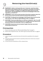
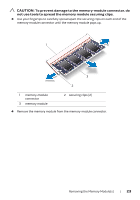
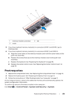
11 Removing the Memory Module(s) WARNING: Before working inside your computer, read the safety information that shipped with your computer and follow the steps in "Before You Begin" on page 9. For additional safety best practices information, see the Regulatory Compliance Homepage at dell.com/ regulatory_compliance. NOTE: Your computer supports up to four memory module connectors. You can access connectors DIMM 1 and DIMM 2 by removing the compartment door at the bottom of your computer. You can access connectors DIMM 3 and DIMM 4 by removing the memory-module cover on top of the palm rest assembly. Prerequsites 1 Remove the battery pack. See "Removing the Battery Pack" on page 12. 2 Remove the compartment door. See "Removing the Compartment Door" on page 14. Procedure 1 To remove memory module(s) from connectors DIMM 1 and DIMM 2, go to step 3. 2 To remove memory-module(s) from connectors DIMM 3 and DIMM 4: a Remove the center control cover. See "Removing the Center Control Cover" on page 41. b Remove the keyboard. See "Removing the Keyboard" on page 45. c Remove the screws that secure the memory-module cover to the palm rest assembly. 2 1 1 memory-module cover 2 screws (3) 22 | Removing the Memory Module(s)
-
 1
1 -
2
-
3
-
4
-
5
-
6
-
7
-
8
-
9
-
10
-
11
-
12
-
13
-
14
-
15
-
16
-
 17
17 -
 18
18 -
 19
19 -
 20
20 -
 21
21 -
 22
22 -
 23
23 -
 24
24 -
 25
25 -
 26
26 -
 27
27 -
28
-
29
-
30
-
31
-
32
-
33
-
34
-
35
-
36
-
37
-
38
-
39
-
40
-
41
-
42
-
43
-
44
-
45
-
46
-
47
-
48
-
49
-
50
-
51
-
52
-
53
-
54
-
55
-
56
-
57
-
58
-
59
-
60
-
61
-
62
-
63
-
64
-
65
-
66
-
67
-
68
-
69
-
70
-
71
-
72
-
73
-
74
-
75
-
76
-
77
-
78
-
79
-
80
-
81
-
82
-
83
-
84
-
85
-
86
-
87
-
88
 |
 |