Dell Alienware M17x R4 Owner's Manual - Page 25
Postrequsites, Start, Control Panel, System and Security, System
 |
View all Dell Alienware M17x R4 manuals
Add to My Manuals
Save this manual to your list of manuals |
Page 25 highlights
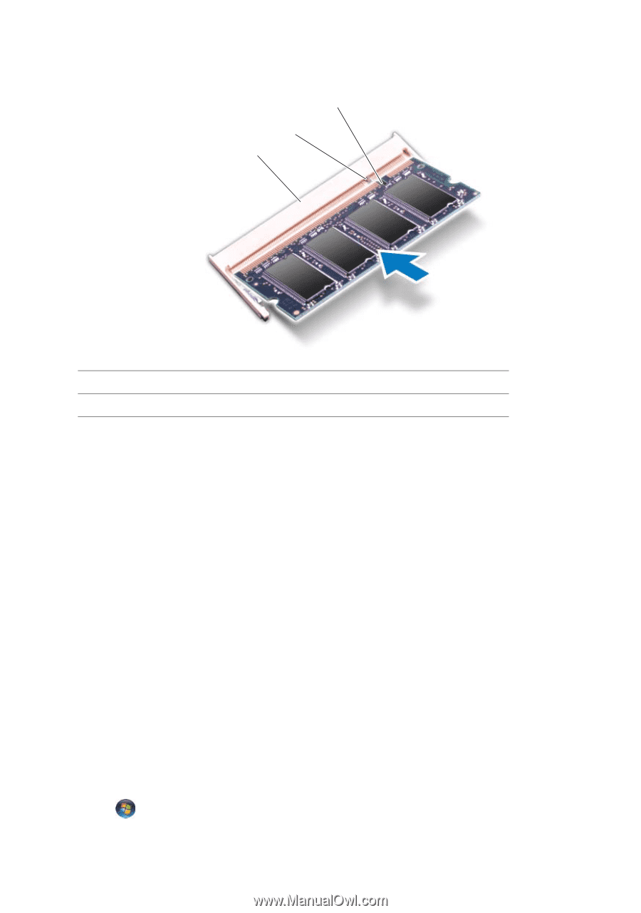
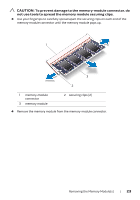
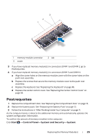
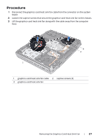
3 2 1 1 memory-module connector 3 notch 2 tab 3 If you have replaced memory module(s) in connectors DIMM 1 and DIMM 2, go to Postrequsites. 4 If you have replaced memory module(s) in connectors DIMM 3 and DIMM 4: a Align the screw holes on the memory-module cover with the screw holes on the palm rest assembly. b Replace the screws that secure the memory-module cover to the palm rest assembly. c Replace the keyboard. See "Replacing the Keyboard" on page 48. d Replace the center control cover. See "Replacing the Center Control Cover" on page 44. Postrequsites 1 Replace the compartment door. See "Replacing the Compartment Door" on page 15. 2 Replace the battery pack. See "Replacing the Battery Pack" on page 13. 3 Follow the instructions in "After Working Inside Your Computer" on page 11. As the computer boots, it detects the additional memory and automatically updates the system configuration information. To confirm the amount of memory installed in the computer: Click Start → Control Panel→ System and Security→ System. Replacing the Memory Module(s) | 25
-
 1
1 -
2
-
3
-
4
-
5
-
6
-
7
-
8
-
9
-
10
-
11
-
12
-
13
-
14
-
15
-
16
-
17
-
18
-
19
-
 20
20 -
 21
21 -
 22
22 -
 23
23 -
 24
24 -
 25
25 -
 26
26 -
 27
27 -
 28
28 -
 29
29 -
 30
30 -
31
-
32
-
33
-
34
-
35
-
36
-
37
-
38
-
39
-
40
-
41
-
42
-
43
-
44
-
45
-
46
-
47
-
48
-
49
-
50
-
51
-
52
-
53
-
54
-
55
-
56
-
57
-
58
-
59
-
60
-
61
-
62
-
63
-
64
-
65
-
66
-
67
-
68
-
69
-
70
-
71
-
72
-
73
-
74
-
75
-
76
-
77
-
78
-
79
-
80
-
81
-
82
-
83
-
84
-
85
-
86
-
87
-
88
 |
 |