Dell Alienware M17x R4 Owner's Manual - Page 40
Replacing the Processor, Module
 |
View all Dell Alienware M17x R4 manuals
Add to My Manuals
Save this manual to your list of manuals |
Page 40 highlights
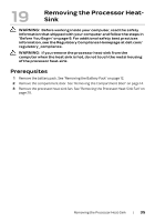
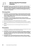
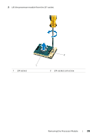
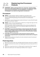
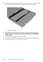
22 Replacing the Processor Module WARNING: Before working inside your computer, read the safety information that shipped with your computer. For additional safety best practices information, see the Regulatory Compliance Homepage at www.dell.com/regulatory_compliance. Procedure NOTE: If a new processor module is installed, you will receive a new thermal-cooling assembly, which will include an affixed thermal pad, or you will receive a new thermal pad along with documentation to illustrate proper installation. 1 Align the pin-1 corner of the processor module with the pin-1 corner of the ZIF socket, then place the processor module. NOTE: The pin-1 corner of the processor module has a triangle that aligns with the triangle on the pin-1 corner of the ZIF socket. When the processor module is properly seated, all four corners are aligned at the same height. If one or more corners of the module are higher than the others, the module is not seated properly. CAUTION: To prevent intermittent contact between the ZIF-socket cam screw and the processor module when replacing the processor, press to apply slight pressure to the center of the processor module while turning the cam screw. CAUTION: To avoid damage to the processor module, hold the screwdriver perpendicular to the processor module when turning the cam screw. 2 Tighten the ZIF socket by turning the cam screw clockwise to secure the processor module to the ZIF socket. Postrequsites 1 Replace the processor heat-sink. See "Replacing the Processor Heat-Sink" on page 37. 2 Replace the processor heat-sink fan. See "Replacing the Processor Heat-Sink Fan" on page 31. 3 Replace the compartment door. See "Replacing the Compartment Door" on page 15. 4 Replace the battery pack. See "Replacing the Battery Pack" on page 13. 40 | Replacing the Processor Module
-
 1
1 -
2
-
3
-
4
-
5
-
6
-
7
-
8
-
9
-
10
-
11
-
12
-
13
-
14
-
15
-
16
-
17
-
18
-
19
-
20
-
21
-
22
-
23
-
24
-
25
-
26
-
27
-
28
-
29
-
30
-
31
-
32
-
33
-
34
-
 35
35 -
 36
36 -
 37
37 -
 38
38 -
 39
39 -
 40
40 -
 41
41 -
 42
42 -
 43
43 -
 44
44 -
 45
45 -
46
-
47
-
48
-
49
-
50
-
51
-
52
-
53
-
54
-
55
-
56
-
57
-
58
-
59
-
60
-
61
-
62
-
63
-
64
-
65
-
66
-
67
-
68
-
69
-
70
-
71
-
72
-
73
-
74
-
75
-
76
-
77
-
78
-
79
-
80
-
81
-
82
-
83
-
84
-
85
-
86
-
87
-
88
 |
 |