Dell Alienware M17x R4 Owner's Manual - Page 51
Replacing the Mini-Card, Procedure
 |
View all Dell Alienware M17x R4 manuals
Add to My Manuals
Save this manual to your list of manuals |
Page 51 highlights
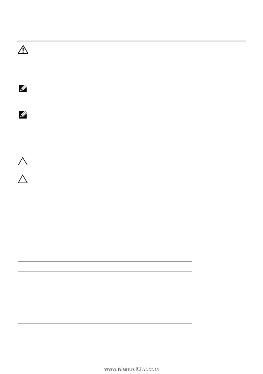
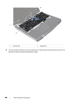
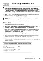
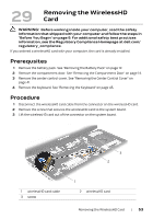
28 Replacing the Mini-Card WARNING: Before working inside your computer, read the safety information that shipped with your computer and follow the steps in "Before You Begin" on page 9. For additional safety best practices information, see the Regulatory Compliance Homepage at dell.com/ regulatory_compliance. NOTE: Dell or Alienware does not guarantee compatibility or provide support for Mini-Cards from sources other than Dell or Alienware. Your computer supports one half Mini-Card slot for WLAN. NOTE: Depending on the configuration of the computer when it was sold, the Mini-Card slot may or may not have a Mini-Card installed. Procedure 1 Remove the new Mini-Card from its packaging. CAUTION: Use firm and even pressure to slide the card into place. If you use excessive force, you may damage the connector. CAUTION: The connectors are keyed to ensure correct insertion. If you feel resistance, check the connectors on the card and on the system board, and realign the card. 2 Insert the Mini-Card connector at a 45-degree angle into the connector on the system board. 3 Press the other end of the Mini-Card down into the slot on the system board and replace the screw that secures the Mini-Card to the system board. 4 Connect the appropriate antenna cables to the Mini-Card you are installing. The following table provides the antenna cable color scheme for the Mini-Card supported by your computer. Connectors on the Mini-Card WLAN (2 or 3 antenna cables) Main WLAN (white triangle) Auxiliary WLAN (black triangle) MIMO WLAN (gray triangle) (optional) Antenna Cable Color Scheme white black gray Replacing the Mini-Card | 51
-
 1
1 -
2
-
3
-
4
-
5
-
6
-
7
-
8
-
9
-
10
-
11
-
12
-
13
-
14
-
15
-
16
-
17
-
18
-
19
-
20
-
21
-
22
-
23
-
24
-
25
-
26
-
27
-
28
-
29
-
30
-
31
-
32
-
33
-
34
-
35
-
36
-
37
-
38
-
39
-
40
-
41
-
42
-
43
-
44
-
45
-
 46
46 -
 47
47 -
 48
48 -
 49
49 -
 50
50 -
 51
51 -
 52
52 -
 53
53 -
 54
54 -
 55
55 -
 56
56 -
57
-
58
-
59
-
60
-
61
-
62
-
63
-
64
-
65
-
66
-
67
-
68
-
69
-
70
-
71
-
72
-
73
-
74
-
75
-
76
-
77
-
78
-
79
-
80
-
81
-
82
-
83
-
84
-
85
-
86
-
87
-
88
 |
 |