Dell Alienware M17x R4 Owner's Manual - Page 65
Removing the Palm Rest Assembly, Media Card Reader cable
 |
View all Dell Alienware M17x R4 manuals
Add to My Manuals
Save this manual to your list of manuals |
Page 65 highlights
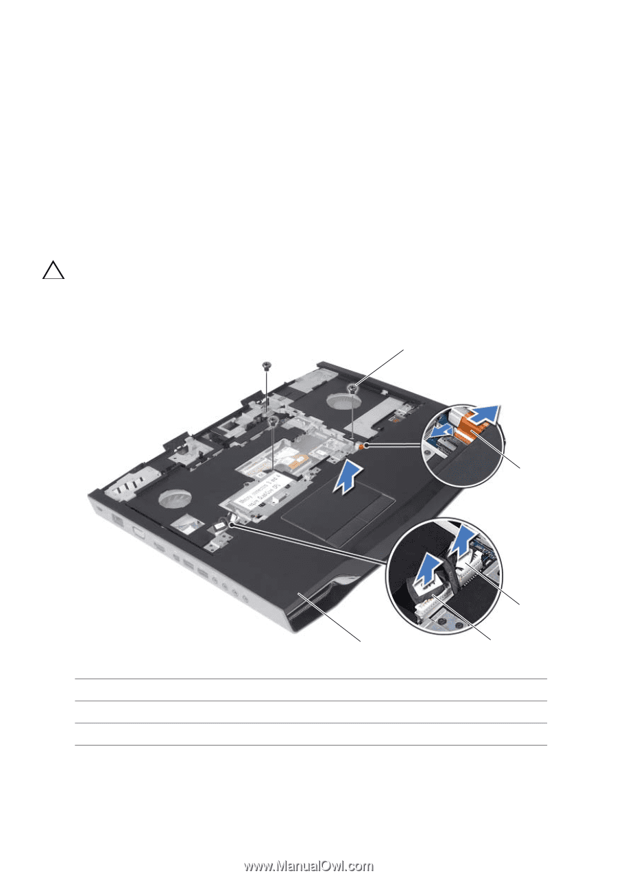
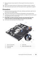
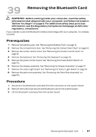
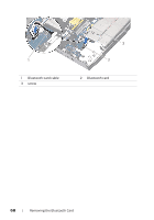
7 Remove the power button board. See "Removing the Power Button Board" on page 55. 8 Remove the display assembly. See "Removing the Display Assembly" on page 57. 9 Remove the status light board. See "Removing the Status Light Board" on page 61. Procedure 1 Disconnect the touch pad cable, LVDS cable, and Media Card Reader cable from the connectors on the system board. 2 Remove the screws that secure the palm rest assembly to the computer base. 3 Carefully pry out the palm rest assembly along the rear edge and then ease the palm rest assembly from the computer base. CAUTION: Carefully separate the palm rest assembly from the computer base to avoid damage to the palm rest assembly. 4 Lift the palm rest assembly off the computer base. 5 4 1 palm rest assembly 3 touch pad cable 5 screws (3) 3 1 2 2 LVDS cable 4 Media Card Reader cable Removing the Palm Rest Assembly | 65
-
 1
1 -
2
-
3
-
4
-
5
-
6
-
7
-
8
-
9
-
10
-
11
-
12
-
13
-
14
-
15
-
16
-
17
-
18
-
19
-
20
-
21
-
22
-
23
-
24
-
25
-
26
-
27
-
28
-
29
-
30
-
31
-
32
-
33
-
34
-
35
-
36
-
37
-
38
-
39
-
40
-
41
-
42
-
43
-
44
-
45
-
46
-
47
-
48
-
49
-
50
-
51
-
52
-
53
-
54
-
55
-
56
-
57
-
58
-
59
-
 60
60 -
 61
61 -
 62
62 -
 63
63 -
 64
64 -
 65
65 -
 66
66 -
 67
67 -
 68
68 -
 69
69 -
 70
70 -
71
-
72
-
73
-
74
-
75
-
76
-
77
-
78
-
79
-
80
-
81
-
82
-
83
-
84
-
85
-
86
-
87
-
88
 |
 |