Dell Dimension 9200 Owner's Manual - Page 82
Memory, Memory Overview - cpu
 |
View all Dell Dimension 9200 manuals
Add to My Manuals
Save this manual to your list of manuals |
Page 82 highlights
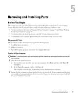
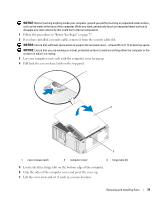
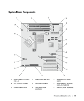
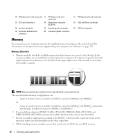
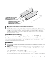
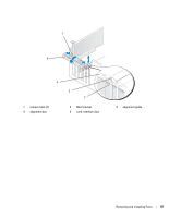
10 PCI Express x1 card connector 11 13 PCI card connectors 14 16 rear fan connector 17 19 processor and heat sink 20 connector PCI Express x16 card connector floppy drive connector (FLOPPY) thermal sensor connector processor power connector 12 PCI Express x4 card connector 15 PS/2 and Serial connector 18 CPU fan connector Memory You can increase your computer memory by installing memory modules on the system board. For information on the type of memory supported by your computer, see "Memory" on page 123. Memory Overview • Memory modules should be installed in pairs of matched memory size, speed, and technology. If the memory modules are not installed in matched pairs, the computer will continue to operate, but with a slight reduction in performance. See the label in the upper-right corner of the module to determine the module's capacity. NOTE: Always install memory modules in the order indicated on the system board. The recommended memory configurations are: - A pair of matched memory modules installed in connectors DIMM_1 and DIMM_2 or - A pair of matched memory modules installed in connectors DIMM_1 and DIMM_2 and another matched pair installed in connectors DIMM_3 and DIMM_4 • If you install mixed pairs of DDR2 533-MHz (PC2-4300), DDR2 667-MHz (PC2-5300), and DDR2 800-MHz (PC2-6400) memory, the modules function at the slowest speed installed. • Be sure to install a single memory module in the DIMM_1 connector, the connector closest to the processor, before you install modules in the other connectors. • While installing memory modules, ensure that you do not mix ECC and non-ECC memory. 82 Removing and Installing Parts
-
 1
1 -
2
-
3
-
4
-
5
-
6
-
7
-
8
-
9
-
10
-
11
-
12
-
13
-
14
-
15
-
16
-
17
-
18
-
19
-
20
-
21
-
22
-
23
-
24
-
25
-
26
-
27
-
28
-
29
-
30
-
31
-
32
-
33
-
34
-
35
-
36
-
37
-
38
-
39
-
40
-
41
-
42
-
43
-
44
-
45
-
46
-
47
-
48
-
49
-
50
-
51
-
52
-
53
-
54
-
55
-
56
-
57
-
58
-
59
-
60
-
61
-
62
-
63
-
64
-
65
-
66
-
67
-
68
-
69
-
70
-
71
-
72
-
73
-
74
-
75
-
76
-
 77
77 -
 78
78 -
 79
79 -
 80
80 -
 81
81 -
 82
82 -
 83
83 -
 84
84 -
 85
85 -
 86
86 -
 87
87 -
88
-
89
-
90
-
91
-
92
-
93
-
94
-
95
-
96
-
97
-
98
-
99
-
100
-
101
-
102
-
103
-
104
-
105
-
106
-
107
-
108
-
109
-
110
-
111
-
112
-
113
-
114
-
115
-
116
-
117
-
118
-
119
-
120
-
121
-
122
-
123
-
124
-
125
-
126
-
127
-
128
-
129
-
130
-
131
-
132
-
133
-
134
-
135
-
136
-
137
-
138
-
139
-
140
-
141
-
142
-
143
-
144
-
145
-
146
-
147
-
148
-
149
-
150
-
151
-
152
-
153
-
154
-
155
-
156
-
157
-
158
-
159
-
160
-
161
-
162
-
163
-
164
-
165
-
166
-
167
-
168
-
169
-
170
-
171
-
172
 |
 |