Dell Dimension E510 Service Manual
Dell Dimension E510 Manual
 |
View all Dell Dimension E510 manuals
Add to My Manuals
Save this manual to your list of manuals |
Dell Dimension E510 manual content summary:
- Dell Dimension E510 | Service Manual - Page 1
Dell™ Dimension™ 5150/E510 Service Manual Before You Begin Technical Overview Specifications Removing the Computer Cover Removing and Installing Parts Replacing the Computer Cover Troubleshooting System Setup Notes, Notices, and Cautions NOTE: A NOTE indicates important information that helps you - Dell Dimension E510 | Service Manual - Page 2
Page Before You Begin Dell™ Dimension™ 5150/E510 Service Manual Getting Started Recommended Tools Turning Off Your Computer Before Working Inside Your Computer Getting Started This section provides procedures for removing and installing the components in your computer. Unless otherwise noted - Dell Dimension E510 | Service Manual - Page 3
or contacts on a card. Hold a card by its edges or by its metal mounting bracket. Hold a component such as a processor by its edges, not by its pins. NOTICE: Only a certified service technician should perform repairs on your computer. Damage due to servicing that is not authorized by Dell is not - Dell Dimension E510 | Service Manual - Page 4
Back to Contents Page Technical Overview Dell™ Dimension™ 5150/E510 Service Manual Front View of the Computer Back View of the Computer Inside View of Your Computer System Board Components Power Supply DC Connector Pin Assignments Front View of the Computer 1 cover latch Use this latch to - Dell Dimension E510 | Service Manual - Page 5
is on the card. 7 headphone Use the headphone connector to attach headphones. connector 8 diagnostic Use the lights to help you troubleshoot a computer problem based on the lights (4) diagnostic code. For more information, see "Diagnostic Lights." 9 hard-drive The hard drive activity light is on - Dell Dimension E510 | Service Manual - Page 6
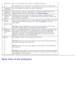
1 voltage selection switch See the safety instructions in the Product Information Guide for more information. 2 power connector Insert the power cable. 3 back panel connectors Plug USB, audio, and other devices into the appropriate connector. 4 card slots Access connectors for any installed PCI - Dell Dimension E510 | Service Manual - Page 7
information on booting to a USB device) It is recommended that you use the front USB connectors for devices that you connect occasionally, such as joysticks or cameras. Inside View of Your Computer CAUTION: Before you begin any of the procedures in this section, follow the safety instructions in - Dell Dimension E510 | Service Manual - Page 8
System Board Components - Dell Dimension E510 | Service Manual - Page 9
Power Supply DC Connector Pin Assignments - Dell Dimension E510 | Service Manual - Page 10
DC Main Power Connector P1 Pin Number 1 2 3 4 5 6 7 8 9 Signal Name +3.3 VDC* +3.3 VDC* COM +5VDC COM +5 VDC COM POK +5 VFP 18-AWG Wire Orange Orange Black Red Black Red Black Gray Purple - Dell Dimension E510 | Service Manual - Page 11
are high current type (9 A current rating/Molex-HCS type). *The +3.3VDC/SE is a brown sense wire for +3.3VDC and is optional. DC Processor Power Connector P2 Pin Number Signal Name 18-AWG Wire 1 COM Black 2 COM Black 3 +12 VADC Yellow 4 +12 VADC Yellow DC Peripheral Connectors P3 - Dell Dimension E510 | Service Manual - Page 12
1 +5 VDC Red 2 COM Black 3 COM Black 4 +12 VADC Yellow DC Peripheral Connectors P8 and P9 Pin Number Signal Name 18-AWG Wire 1 +12 VBDC White 2 COM Black 3 COM Black 4 +5 VDC Red Back to Contents Page - Dell Dimension E510 | Service Manual - Page 13
Contents Page Specifications Dell™ Dimension™ 5150/E510 Service Manual Processor Processor type Level 1 (L1) cache Level 2 (L2) cache Memory Type Memory connectors Memory capacities Maximum memory BIOS address Computer Information Chipset RAID Support DMA channels Interrupt levels BIOS chip (NVRAM - Dell Dimension E510 | Service Manual - Page 14
(GMA950) Audio Type Sigmatel drive bays Serial ATA drives (2), floppy drive, USB memory devices, CD drive, CD-RW drive, DVD drive, DVD-RW drive, DVD and CDRW combo drive, and Media Card Reader two bays for 1-inch high serial ATA hard drives Connectors External connectors: Video Network adapter - Dell Dimension E510 | Service Manual - Page 15
for power-on state. amber light - Blinking amber indicates a problem with the power supply inside the computer. If the system cannot boot and there is a solid amber light, this indicates a problem with the system board (see "Power Problems" in your computer Owner's Manual). Hard-drive access light - Dell Dimension E510 | Service Manual - Page 16
Heat dissipation 1041 BTU/hr Voltage (see the safety instructions in the Product Information Guide for important voltage setting information) 90 to 135 V and 180 to 265 V at 50/60 Hz Backup battery 3-V CR2032 lithium coin cell Physical Height Width Depth Weight 41.1 cm (16.2 inches) 18.8 cm - Dell Dimension E510 | Service Manual - Page 17
Page Removing the Computer Cover Dell™ Dimension™ 5150/E510 Service Manual CAUTION: Before you begin any of the procedures in this section, follow the safety instructions in the Product Information Guide. CAUTION: To guard against electrical shock, always unplug your computer from the electrical - Dell Dimension E510 | Service Manual - Page 18
and Installing Parts Dell™ Dimension™ 5150/E510 Service Manual Memory Cards Drive Panel Front Panel Drives Hard Drive Floppy Drive Media Card Reader (Optional) CD/DVD Drive Heat Sink Assembly Processor Fan Assembly Front I/O Panel System Board Power Supply Memory You - Dell Dimension E510 | Service Manual - Page 19
in DIMM connectors 1 and 2 or DIMM connectors 3 and 4. Addressing Memory With 4-GB Configurations Your computer supports a maximum of 4 GB of memory when you use four 1-GB DIMMs. Current operating systems, such as Microsoft® Windows® XP, can use a maximum of 4 GB of address space; however, the - Dell Dimension E510 | Service Manual - Page 20
to remove it from the connector. Installing Memory CAUTION: Before you begin any of the procedures in this section, follow the safety instructions in the Product Information Guide. NOTICE: To prevent static damage to components inside your computer, discharge static electricity from your body before - Dell Dimension E510 | Service Manual - Page 21
® Windows® desktop and click Properties. 11. Click the General tab. 12. To verify that the memory is installed correctly, check the amount of memory (RAM) listed. Cards CAUTION: Before you begin any of the procedures in this section, follow the safety instructions in the Product Information Guide. - Dell Dimension E510 | Service Manual - Page 22
an unpainted metal surface on the computer chassis. Your Dell™ computer provides the following slots for PCI and PCI Express cards: Two PCI card slots One PCI Express x16 card slot One PCI Express x1 card slot PCI Cards Your computer supports two PCI cards. If you are installing or replacing - Dell Dimension E510 | Service Manual - Page 23
for installation. See the documentation that came with the card for information on configuring the card, making internal connections, or otherwise customizing it for your computer. CAUTION: Some network adapters automatically start the computer when they are connected to a network. To guard against - Dell Dimension E510 | Service Manual - Page 24
plug it into the computer. 11. Replace the computer cover, reconnect the computer and devices to electrical outlets, and then turn them on. 12. If you installed a sound card: a. Enter system setup, select Audio Controller, and then change the setting to Off. b. Connect external audio devices to the - Dell Dimension E510 | Service Manual - Page 25
turn them on. 7. Remove the card's driver from the operating system. 8. If you removed a sound card: a. Enter system setup, select Audio Controller, and then change the setting to On. b. Connect external audio devices to the audio connectors on the back panel of the computer. 9. If you removed an - Dell Dimension E510 | Service Manual - Page 26
it in place. b. Set the retention mechanism aside in a secure location. 5. If you are installing a new card, remove the filler bracket to create a card-slot opening. Then continue with step 6. 6. If you are replacing a card that is already installed in the computer, remove the card. If necessary - Dell Dimension E510 | Service Manual - Page 27
is fully seated in the slot. 1 bracket within slot 4 alignment guide 2 bracket caught outside of slot 5 fully seated card 3 alignment bar 6 not fully seated card 10. If you replaced a card that was already installed in the computer and you removed the retention mechanism, you may reinstall the - Dell Dimension E510 | Service Manual - Page 28
plug it into the computer. 13. Replace the computer cover, reconnect the computer and devices to electrical outlets, and then turn them on. 14. If you installed a sound card: a. Enter system setup, select Audio Controller, and then change the setting to Off. b. Connect external audio devices to the - Dell Dimension E510 | Service Manual - Page 29
turn them on. 9. Remove the card's driver from the operating system. 10. If you removed a sound card: a. Enter system setup, select Audio Controller, and then change the setting to On. b. Connect external audio devices to the audio connectors on the back panel of the computer. 11. If you removed an - Dell Dimension E510 | Service Manual - Page 30
open. NOTE: The sliding plate secures and releases the drive panel and helps to secure the drives. 4. Pivot the drive panel outward and lift it away from the computer. 5. Set the drive panel aside in a secure location. Removing the Drive-Panel Insert 1. Follow the procedures in "Before You Begin - Dell Dimension E510 | Service Manual - Page 31
tab away from the drive panel. 3. Pivot the drive-panel insert out and away from the drive panel. 4. Set the drive-panel insert aside in a secure location. Replacing the Drive-Panel Insert 1 drive-panel insert tab 3 center drive-panel tab 2 drive panel insert 4 drive panel 1. Slide the tab - Dell Dimension E510 | Service Manual - Page 32
the side-door hinges. 5. Rotate the drive panel toward the computer until it snaps into place on the front panel. Front Panel CAUTION: Before you begin any of the procedures in this section, follow the safety instructions in the Product Information Guide. CAUTION: To guard against electrical shock - Dell Dimension E510 | Service Manual - Page 33
. 1 top front-panel release tabs (4) 2 front-panel screws (2) 3 front panel 4 bottom front-panel release tabs (4) Drives Your computer supports a combination of these devices: Up to two serial ATA hard drives One FlexBay drive (may contain an optional floppy drive or an optional Media Card Reader) - Dell Dimension E510 | Service Manual - Page 34
cable is the master or boot device (drive 0), and the device attached to the middle connector on the interface cable is the slave device (drive 1). See the drive documentation in your upgrade kit for information on configuring devices for the cable select setting. Connecting and Disconnecting - Dell Dimension E510 | Service Manual - Page 35
cable, locate the power connector on the power supply. 1 SATA power cable connector 3 power cable connector 2 power connector 4 power connector Hard Drive CAUTION: Before you begin any of the procedures in this section, follow the safety instructions in the Product Information Guide. CAUTION: To - Dell Dimension E510 | Service Manual - Page 36
cable from your hard drive or from the system board. 3. Disconnect the power and data cables from the drive. 1 serial ATA data cable 2 power cable 4. Press the blue tabs on either side of the hard drive bracket toward each other and slide the drive up and out of the computer. 1 hard drive 2 tabs (2) - Dell Dimension E510 | Service Manual - Page 37
bracket from the old drive by unsnapping it from the drive. Snap the bracket onto the new drive. 1 drive 2 hard drive bracket 6. Gently slide the drive into place until you feel a click or feel the drive securely installed. 7. Connect the power and hard-drive cables to the drive. 1 serial ATA data - Dell Dimension E510 | Service Manual - Page 38
any software required for drive operation. Adding a Second Hard Drive CAUTION: Before you begin any of the procedures in this section, follow the safety instructions in the Product Information Guide. CAUTION: To guard against electrical shock, always unplug your computer from the electrical outlet - Dell Dimension E510 | Service Manual - Page 39
." 2. Remove the computer cover. 3. Remove the drive panel. 1 power cable 2 data cable 4. Disconnect the power and data cables from the back of the floppy drive. NOTE: If you are installing a PCI Express x16 card, the card may cover the floppy-drive connectors. Remove the card before connecting the - Dell Dimension E510 | Service Manual - Page 40
lever toward the bottom of the computer and, without releasing the sliding plate lever, slide the floppy drive out through the front of the computer. 1 sliding plate lever 2 sliding plate 3 floppy drive Installing a Floppy Drive NOTE: If the new floppy drive does not include shoulder screws, use - Dell Dimension E510 | Service Manual - Page 41
outlets, and turn them on. See the documentation that came with the drive for instructions on installing any software required for drive operation. 11. Enter system setup and select the appropriate Diskette Drive option. 12. Verify that your computer works correctly by running the Dell Diagnostics. - Dell Dimension E510 | Service Manual - Page 42
Reader, see your Owner's Manual. Removing a Media Card Reader CAUTION: Before you begin any of the procedures in this section, follow the safety instructions in the Product Information Guide. NOTICE: To prevent static damage to components inside your computer, discharge static electricity from your - Dell Dimension E510 | Service Manual - Page 43
out through the front of the computer. 6. Replace the drive panel. 7. Replace the computer cover. Installing a Media Card Reader CAUTION: Before you begin any of the procedures in this section, follow the safety instructions in the Product Information Guide. NOTICE: To prevent static damage to - Dell Dimension E510 | Service Manual - Page 44
Remove the computer cover. 3. Remove the drive panel. 4. Remove the Media Card Reader from its packaging and ensure that all of the screws are included. 5. Slide the Media Card Reader into place until you feel a click or feel the drive securely installed. NOTE: Ensure that the Media Card Reader is - Dell Dimension E510 | Service Manual - Page 45
Card Reader 2 FlexBay USB cable 7. Route the FlexBay USB cable through the cable routing clip. 8. Replace the drive panel. 9. Replace the computer cover. CD/DVD Drive CAUTION: Before you begin any of the procedures in this section, follow the safety instructions in the Product Information Guide - Dell Dimension E510 | Service Manual - Page 46
out through the front of the computer. Installing a CD/DVD Drive 1. Follow the procedures in "Before You Begin." 2. Remove the computer cover. 3. Remove the drive panel. NOTE: If you are installing a new drive, you need to remove the drive-panel insert. 4. Slide the drive into place until you feel - Dell Dimension E510 | Service Manual - Page 47
a network cable, first plug the cable into the network port or device and then plug it into the computer. 9. Connect your computer and devices to their electrical outlets, and turn them on. See the documentation that came with the drive for instructions on installing any software required for - Dell Dimension E510 | Service Manual - Page 48
setup and select the appropriate Drive option. 11. Verify that your computer works correctly by running the Dell Diagnostics. Heat-Sink Assembly CAUTION: Before you begin any of the procedures in this section, follow the safety instructions in the Product Information Guide. CAUTION: To guard against - Dell Dimension E510 | Service Manual - Page 49
instructions in the Product Information Guide. CAUTION: To guard against electrical shock, always unplug your computer computer cover. NOTICE: If you are installing a processor upgrade kit from Dell, discard the original heat-sink assembly. If you are not installing a processor upgrade kit from Dell - Dell Dimension E510 | Service Manual - Page 50
the socket is ready for the new processor. Installing the Processor NOTICE: Ground yourself by touching an unpainted metal surface on the back of the computer. NOTICE: When installing the processor, do not touch any of the pins inside the socket or allow any objects to fall onto the pins in - Dell Dimension E510 | Service Manual - Page 51
do not use excessive force when you install the processor. 5. Set the processor lightly in the socket and ensure that the processor is positioned correctly. . NOTICE: If you are not installing a processor upgrade kit from Dell, reuse the original heat-sink assembly when you replace the processor - Dell Dimension E510 | Service Manual - Page 52
Assembly CAUTION: Before you begin any of the procedures in this section, follow the safety instructions in the Product Information Guide. CAUTION: To guard against electrical shock, always unplug your computer from the electrical outlet before removing the cover. NOTICE: To prevent static damage to - Dell Dimension E510 | Service Manual - Page 53
Panel CAUTION: Before you begin any of the procedures in this section, follow the safety instructions in the Product Information Guide. CAUTION: To guard against electrical shock, always unplug your computer from the electrical outlet before removing the cover. NOTICE: To prevent static damage to - Dell Dimension E510 | Service Manual - Page 54
6. Pull the I/O panel toward the back of the computer and lift the panel to remove from the computer. 7. Disconnect any cables from the I/O panel. System Board Jumper Settings The jumper locations are shown below. Jumper Setting PSWD Description Password features are enabled. (default) Password - Dell Dimension E510 | Service Manual - Page 55
attached devices from their electrical outlets, and then press the power button to ground the system board. 5. Remove the computer cover. 6. Remove any components that restrict access to the system board (CD/DVD drives, floppy drive, hard drive, front I/O panel). 7. Remove the heat-sink assembly and - Dell Dimension E510 | Service Manual - Page 56
into the network port or device, and then plug the cable into the computer. 6. Connect your computer and devices to electrical outlets, and turn them on. Power Supply CAUTION: Before you begin any of the procedures in this section, follow the safety instructions in the Product Information Guide. - Dell Dimension E510 | Service Manual - Page 57
metal surface on the computer chassis. Removing the Power Supply 1. Follow the procedures in "Before You Begin." 2. Remove the computer cover. 3. Disconnect the DC power cables from the system board and the drives. 1 release button 2 power supply 3 screws (4) 4 AC power connector NOTICE: Note the - Dell Dimension E510 | Service Manual - Page 58
7. Lift the power supply out of the computer. Replacing the Power Supply CAUTION: Before you begin any of the procedures in this section, follow the safety instructions in the Product Information Guide. 1. Slide the power supply into place. 2. Reattach the screws that secure the power supply to the - Dell Dimension E510 | Service Manual - Page 59
Computer Cover Dell™ Dimension™ 5150/E510 Service Manual CAUTION: Before you begin any of the procedures in this section, follow the safety instructions in the Product Information Guide. 1. Ensure that all cables are connected, and fold cables out of the way. 2. Ensure that no tools or extra parts - Dell Dimension E510 | Service Manual - Page 60
Page Troubleshooting Dell™ Dimension™ 5150/E510 Service Manual Dell Diagnostics System Lights Diagnostic Lights Beep Codes Dell Diagnostics CAUTION: Before you begin any of the procedures in this section, follow the safety instructions in the Product Information Guide. NOTE: The Drivers and - Dell Dimension E510 | Service Manual - Page 61
an error code and a description of the problem. Write down the error code and problem description and follow the instructions on the screen. If you cannot resolve the error condition, contact Dell (see your computer Owner's Manual for information about how to contact Dell). NOTE: The Service Tag - Dell Dimension E510 | Service Manual - Page 62
Dell). Blinking amber A power supply or system board Check the diagnostic lights to see if the specific problem is failure has occurred. identified. Also, see "Power Problems" in your computer Owner's Manual . Solid green and a beep A problem was detected while code during POST the BIOS - Dell Dimension E510 | Service Manual - Page 63
a graphics card that you know works and restart the computer. If the problem persists or the computer has integrated graphics, contact Dell (see your computer Owner's Manual for information about how to contact Dell). A possible floppy or hard drive failure has occurred. Reseat all power and - Dell Dimension E510 | Service Manual - Page 64
Dell). The computer is in a normal None. operating condition after POST. NOTE: The diagnostic lights are not lit after the system successfully boots to the operating system. Beep Codes Your computer might emit a series of beeps during start-up if the monitor cannot display errors or problems - Dell Dimension E510 | Service Manual - Page 65
Back to Contents Page System Setup Dell™ Dimension™ 5150/E510 Service Manual Overview Entering System Setup System Setup Screens System Setup Options Boot Sequence Clearing Forgotten Passwords Clearing CMOS Settings Overview Use system setup as follows: To change the system - Dell Dimension E510 | Service Manual - Page 66
System System Info Displays the System name, BIOS Version number, BIOS Date, Service Tag, Express Service Code, and Asset Tag. NOTE: The system name listed in the BIOS may not appear exactly as the name that appears on the computer or in the computer's documentation. Processor Info Displays the - Dell Dimension E510 | Service Manual - Page 67
and restart the computer, this option appears in the system setup menu. To boot from a USB memory device, select the USB device and move it so it becomes the first device in the list. Drives Diskette Drive (Internal default) Enables and disables the floppy drives and sets read permission for - Dell Dimension E510 | Service Manual - Page 68
, this option will appear only when a supported processor is installed. HDD Acoustic Mode Bypass - Your computer does not test or change the current acoustics mode setting. Quiet - The hard drive operates at its most quiet setting. Suggested - The hard drive operates at the level suggested by the - Dell Dimension E510 | Service Manual - Page 69
in a low-power mode S3 - sets the computer to a standby state where the power is reduced or turned off for most components; however, system memory remains active for both settings Maintenance SERR DMI Controls the SERR DMI message mechanism. Message (On NOTE: Some graphics cards require that the - Dell Dimension E510 | Service Manual - Page 70
the next bootable device in the sequence. NOTE: If there is a non-bootable floppy disk in the drive, the computer generates an error message. Follow the on-screen instructions to retry the boot. Hard Drive - The computer attempts to boot from the primary hard drive. If there is no operating system - Dell Dimension E510 | Service Manual - Page 71
highlight the Boot Sequence menu option and press to access the menu. NOTE: Write down your current boot sequence in case you want to restore it. procedures in this section, follow the safety instructions located in the Product Information Guide. 1. Follow the procedures in Getting Started - Dell Dimension E510 | Service Manual - Page 72
outlets, and turn them on. 5. After the Microsoft® Windows® desktop appears on your computer, shut down the computer (see Turning Off Your Computer). 6. Turn off the monitor and disconnect it from the electrical outlet. 7. Disconnect the computer power cable from the electrical outlet, and press the
-
 1
1 -
 2
2 -
 3
3 -
 4
4 -
 5
5 -
 6
6 -
 7
7 -
8
-
9
-
10
-
11
-
12
-
13
-
14
-
15
-
16
-
17
-
18
-
19
-
20
-
21
-
22
-
23
-
24
-
25
-
26
-
27
-
28
-
29
-
30
-
31
-
32
-
33
-
34
-
35
-
36
-
37
-
38
-
39
-
40
-
41
-
42
-
43
-
44
-
45
-
46
-
47
-
48
-
49
-
50
-
51
-
52
-
53
-
54
-
55
-
56
-
57
-
58
-
59
-
60
-
61
-
62
-
63
-
64
-
65
-
66
-
67
-
68
-
69
-
70
-
71
-
72
 |
 |

Dell™ Dimension™ 5150/E510 Service Manual
Before You Begin
Technical Overview
Specifications
Removing the Computer Cover
Removing and Installing Parts
Replacing the Computer Cover
Troubleshooting
System Setup
Notes, Notices, and Cautions
NOTE:
A NOTE indicates important information that helps you make better use of your computer.
NOTICE:
A NOTICE indicates either potential damage to hardware or loss of data and tells you how to avoid the
problem.
CAUTION:
A CAUTION indicates a potential for property damage, personal injury, or death.
If you purchased a Dell™ n Series computer, any references in this document to Microsoft®
Windows® operating systems are
not applicable.
Information in this document is subject to change without notice.
© 2005–2006 Dell Inc. All rights reserved.
Reproduction in any manner whatsoever without the written permission of Dell Inc.
is strictly forbidden.
Trademarks used in this text:
Dell
, the
DELL
logo, and
Dimension
are trademarks of Dell Inc.;
Intel, Intel SpeedStep
, and
Pentium
are registered
trademarks of Intel Corporation;
Microsoft
and
Windows
are registered trademarks of Microsoft Corporation.
Other trademarks and trade names may be used in this document to refer to either the entities claiming the marks and names or their products.
Dell Inc. disclaims any proprietary interest in trademarks and trade names other than its own.
Model DCSM
August 2006
Rev. A01