Dell External OEMR R410 Technical Guide - Page 16
Power Supply Indicators
 |
View all Dell External OEMR R410 manuals
Add to My Manuals
Save this manual to your list of manuals |
Page 16 highlights
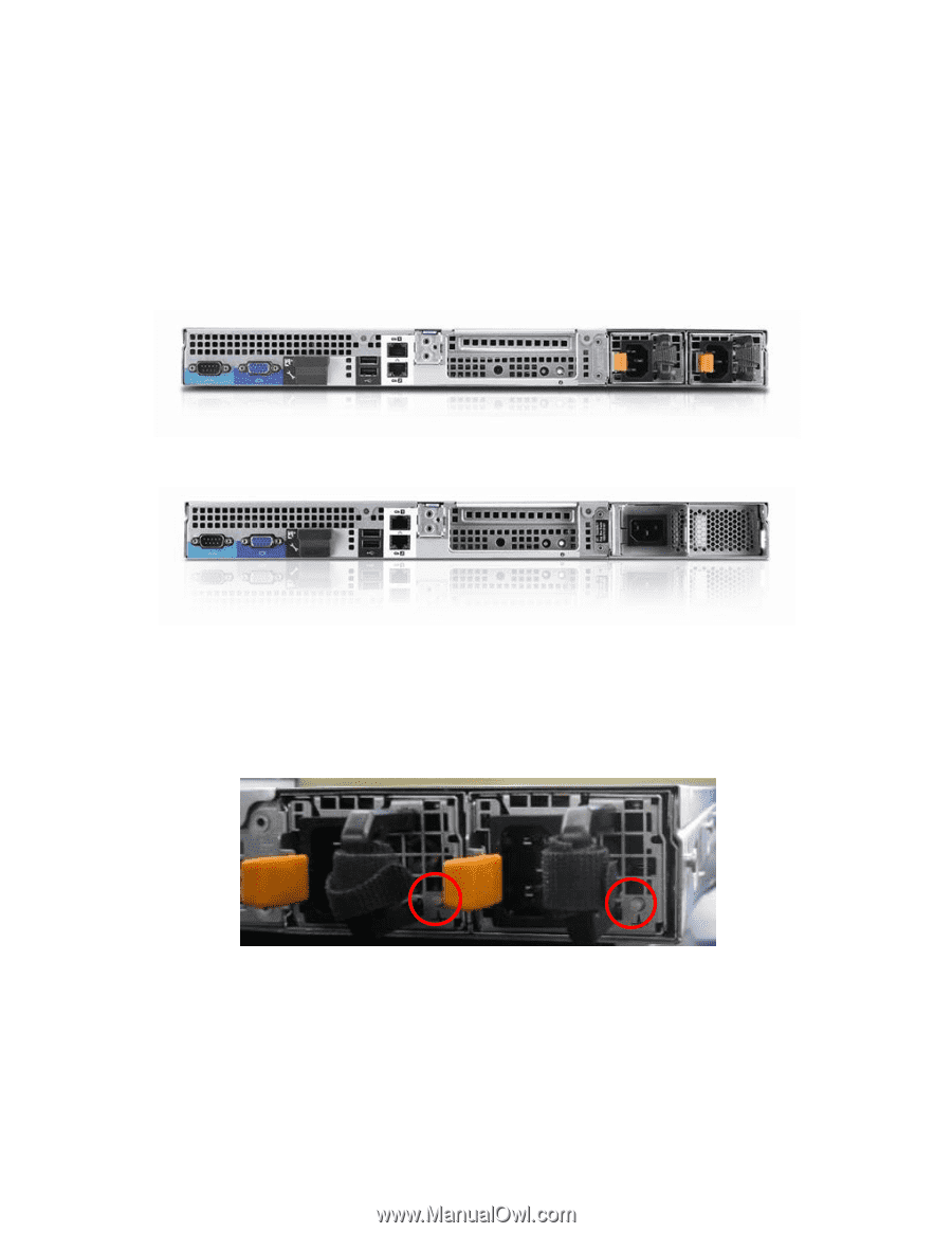
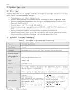
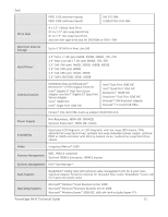
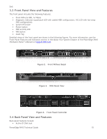
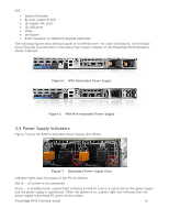
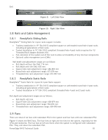
Dell System ID button Bi-color system ID LED (2) Gigabit NIC ports (2) USB ports Video Serial port RJ45 Connector on iDRAC6 Enterprise (optional) The following figures show the back panel of the R410 server. For more information, see the BackPanel Features and Indicators in the About Your System Chapter of the PowerEdge R410 Hardware Owner's Manual. Figure 5. With Redundant Power Supply Figure 6. With Non-redundant Power Supply 3.5 Power Supply Indicators Figure 7 shows the R410's redundant Power Supply Unit (PSUs) Figure 7. Redundant Power Supply Units Indicator lights show the status of the PSU as follows: Not lit - AC power is not connected. Green - In standby mode, a green light indicates a valid AC source is connected to the power supply and the power supply is operational. When the system is on, a green light also indicates that the power supply is providing DC power to the system. PowerEdge R410 Technical Guide 16
-
 1
1 -
2
-
3
-
4
-
5
-
6
-
7
-
8
-
9
-
10
-
 11
11 -
 12
12 -
 13
13 -
 14
14 -
 15
15 -
 16
16 -
 17
17 -
 18
18 -
 19
19 -
 20
20 -
 21
21 -
22
-
23
-
24
-
25
-
26
-
27
-
28
-
29
-
30
-
31
-
32
-
33
-
34
-
35
-
36
-
37
-
38
-
39
-
40
-
41
-
42
-
43
-
44
-
45
-
46
-
47
-
48
-
49
-
50
-
51
-
52
-
53
-
54
-
55
-
56
-
57
-
58
 |
 |