Dell External OEMR R410 Technical Guide - Page 19
Control Panel/LCD
 |
View all Dell External OEMR R410 manuals
Add to My Manuals
Save this manual to your list of manuals |
Page 19 highlights
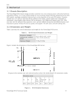
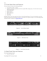
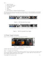
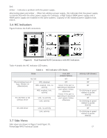
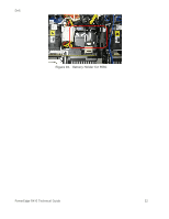
Dell Figure 11. R410 Fans 3.10 Control Panel/LCD Figure 12 shows the front controller board with LCD. LCD module and cable/connector Internal USB Connectors LCD Module and Cable/Connector Figure 12. Front Controller Board with LCD Figure 13 shows the front controller board with the LED. Figure 13. Front Controller Board with Diagnostic LED PowerEdge R410 Technical Guide 19
-
 1
1 -
2
-
3
-
4
-
5
-
6
-
7
-
8
-
9
-
10
-
11
-
12
-
13
-
 14
14 -
 15
15 -
 16
16 -
 17
17 -
 18
18 -
 19
19 -
 20
20 -
 21
21 -
 22
22 -
 23
23 -
 24
24 -
25
-
26
-
27
-
28
-
29
-
30
-
31
-
32
-
33
-
34
-
35
-
36
-
37
-
38
-
39
-
40
-
41
-
42
-
43
-
44
-
45
-
46
-
47
-
48
-
49
-
50
-
51
-
52
-
53
-
54
-
55
-
56
-
57
-
58
 |
 |
Dell
PowerEdge R410 Technical Guide
19
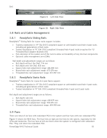
Figure 11.
R410 Fans
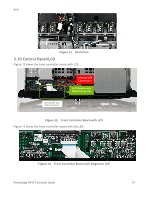
3.10
Control Panel/LCD
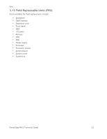
Figure 12 shows the front controller board with LCD.
Figure 12.
Front Controller Board with LCD
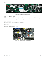
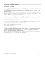
Figure 13 shows the front controller board with the LED.
Figure 13.
Front Controller Board with Diagnostic LED
LCD module and
cable/connector
Internal USB
Connectors
LCD Module and
Cable/Connector