Dell External OEMR R620 Owners Manual - Page 10
inch Dell PowerEdge Express Flash devices PCIe SSDs., Indicator, Button, or
 |
View all Dell External OEMR R620 manuals
Add to My Manuals
Save this manual to your list of manuals |
Page 10 highlights
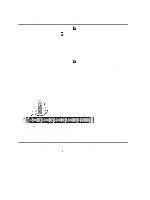
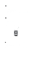
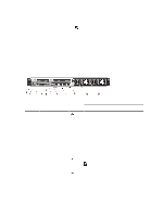
Item Indicator, Button, or Icon Description Connector NOTE: DVD devices are data only. 6 vFlash media card slot Allows you to insert a vFlash media card. 7 LCD menu buttons 8 LCD panel 9 Information tag 10 Video connector Allows you to navigate the control panel LCD menu. Displays system ID, status information, and system error messages. The LCD lights blue during normal system operation. The LCD lights amber when the system needs attention, and the LCD panel displays an error code followed by descriptive text. NOTE: If the system is connected to AC power and an error is detected, the LCD lights amber regardless of whether the system is turned on or off. A slide-out label panel, which allows you to record system information, such as Service Tag, NIC, MAC address, and so on as per your need. Allows you to connect a VGA display to the system. 11 Hard drives (8) Up to eight 2.5 inch hot-swappable hard drives. Up to four 2.5 hot-swappable hard drives and up to two 2.5 inch Dell PowerEdge Express Flash devices (PCIe SSDs). Figure 2. Front-Panel Features and Indicators-10 Hard Drive System Item Indicator, Button, or Icon Description Connector 1 Diagnostic indicators The diagnostic indicators light up to display error status. 2 System health indicator The system health indicator blinks amber when a system fault is detected. 3 Power-on indicator, power button The power-on indicator lights when the system power is on. The power button controls the power supply output to the system. 10
-
 1
1 -
2
-
3
-
4
-
 5
5 -
 6
6 -
 7
7 -
 8
8 -
 9
9 -
 10
10 -
 11
11 -
 12
12 -
 13
13 -
 14
14 -
 15
15 -
16
-
17
-
18
-
19
-
20
-
21
-
22
-
23
-
24
-
25
-
26
-
27
-
28
-
29
-
30
-
31
-
32
-
33
-
34
-
35
-
36
-
37
-
38
-
39
-
40
-
41
-
42
-
43
-
44
-
45
-
46
-
47
-
48
-
49
-
50
-
51
-
52
-
53
-
54
-
55
-
56
-
57
-
58
-
59
-
60
-
61
-
62
-
63
-
64
-
65
-
66
-
67
-
68
-
69
-
70
-
71
-
72
-
73
-
74
-
75
-
76
-
77
-
78
-
79
-
80
-
81
-
82
-
83
-
84
-
85
-
86
-
87
-
88
-
89
-
90
-
91
-
92
-
93
-
94
-
95
-
96
-
97
-
98
-
99
-
100
-
101
-
102
-
103
-
104
-
105
-
106
-
107
-
108
-
109
-
110
-
111
-
112
-
113
-
114
-
115
-
116
-
117
-
118
-
119
-
120
-
121
-
122
-
123
-
124
-
125
-
126
-
127
-
128
-
129
-
130
-
131
-
132
-
133
 |
 |