Dell External OEMR R620 Owners Manual - Page 15
Back-Panel Features And Indicators
 |
View all Dell External OEMR R620 manuals
Add to My Manuals
Save this manual to your list of manuals |
Page 15 highlights
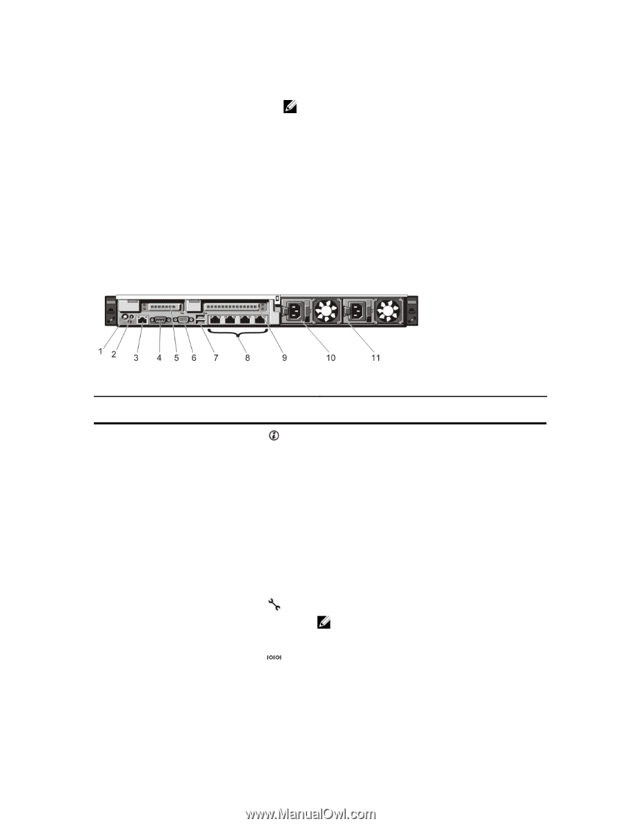
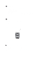
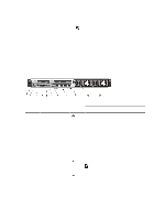
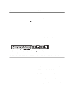
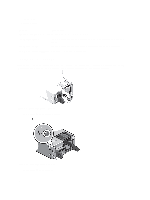
Drive-Status Indicator Pattern (RAID Only) Blinks green, amber, and off Blinks amber four times per second Blinks green slowly Steady green Blinks green three seconds, amber three seconds, and off six seconds Condition NOTE: The drive status indicator remains off until all hard drives are initialized after the system is turned on. Drives are not ready for insertion or removal during this time. Predicted drive failure Drive failed Drive rebuilding Drive online Rebuild aborted Back-Panel Features And Indicators Figure 5. Back-Panel Features and Indicators-8 Hard Drive System (2 PCIe Expansion Cards) Item Indicator, Button, or Icon Description Connector 1 System identification button 2 System identification connector The identification buttons on the front and back panels can be used to locate a particular system within a rack. When one of these buttons is pressed, the LCD panel on the front and the system status indicator on the back blink until one of the buttons is pressed again. Press to toggle the system ID on and off. If the system stops responding during POST, press and hold the system ID button for more than five seconds to enter BIOS progress mode. To reset iDRAC (if not disabled in F2 iDRAC setup) press and hold for more than 15 seconds. Allows you to connect the optional system status indicator assembly through the optional cable management arm. 3 iDRAC7 Enterprise port Dedicated management port. NOTE: The port is available for use only if the iDRAC7 Enterprise license is installed on your system. 4 Serial connector Allows you to connect a serial device to the system. 5 PCIe expansion card slot (riser 2) Allows you to connect a PCIe expansion card. 15
-
 1
1 -
2
-
3
-
4
-
5
-
6
-
7
-
8
-
9
-
 10
10 -
 11
11 -
 12
12 -
 13
13 -
 14
14 -
 15
15 -
 16
16 -
 17
17 -
 18
18 -
 19
19 -
 20
20 -
21
-
22
-
23
-
24
-
25
-
26
-
27
-
28
-
29
-
30
-
31
-
32
-
33
-
34
-
35
-
36
-
37
-
38
-
39
-
40
-
41
-
42
-
43
-
44
-
45
-
46
-
47
-
48
-
49
-
50
-
51
-
52
-
53
-
54
-
55
-
56
-
57
-
58
-
59
-
60
-
61
-
62
-
63
-
64
-
65
-
66
-
67
-
68
-
69
-
70
-
71
-
72
-
73
-
74
-
75
-
76
-
77
-
78
-
79
-
80
-
81
-
82
-
83
-
84
-
85
-
86
-
87
-
88
-
89
-
90
-
91
-
92
-
93
-
94
-
95
-
96
-
97
-
98
-
99
-
100
-
101
-
102
-
103
-
104
-
105
-
106
-
107
-
108
-
109
-
110
-
111
-
112
-
113
-
114
-
115
-
116
-
117
-
118
-
119
-
120
-
121
-
122
-
123
-
124
-
125
-
126
-
127
-
128
-
129
-
130
-
131
-
132
-
133
 |
 |