Dell External OEMR R620 Owners Manual - Page 16
Two integrated 100 Mbps/1 Gbps/10 Gbps SFP, Two integrated 10/100/1000 Mbps NIC connectors
 |
View all Dell External OEMR R620 manuals
Add to My Manuals
Save this manual to your list of manuals |
Page 16 highlights
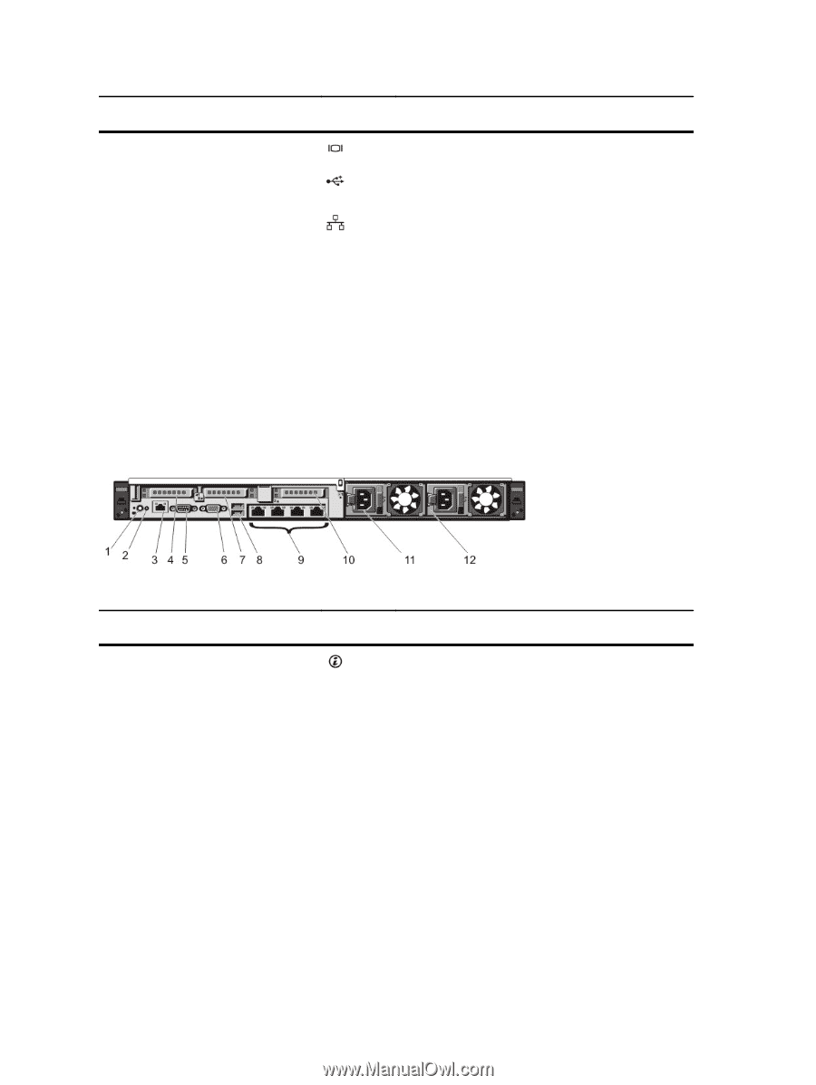
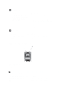
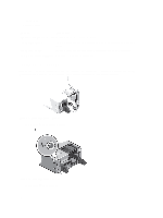
Item Indicator, Button, or Icon Description Connector 6 Video connector Allows you to connect a VGA display to the system. 7 USB connectors (2) 8 Ethernet connectors (4) Allows you to connect USB devices to the system. The ports are USB 2.0-compliant. Four integrated 10/100/1000 Mbps NIC connectors or Four integrated connectors: • Two integrated 10/100/1000 Mbps NIC connectors • Two integrated 100 Mbps/1 Gbps/10 Gbps SFP+ connectors 9 PCIe expansion card slot (riser 3) 10 Power supply (PSU1) 11 Power supply (PSU2) Allows you to connect a PCIe expansion card. AC 495 W, 750 W, or 1100 W Or DC 1100 W (when available) Figure 6. Back-Panel Features and Indicators-10 Hard Drive System and 8 Hard Drive System (3 PCIe Expansion Cards) Item Indicator, Button, or Icon Description Connector 1 System identification button The identification buttons on the front and back panels can be used to locate a particular system within a rack. 10 Hard Drive System When one of these buttons is pressed, the system status indicator on the back flashes until one of the buttons is pressed again. 8 Hard Drive System When one of these buttons is pressed, the LCD panel on the front and the system status indicator on the back flashes until one of the buttons is pressed again. Press to toggle the system ID on and off. If the system stops responding during POST, press and hold the system ID button for more than five seconds to enter BIOS progress mode. 16
-
 1
1 -
2
-
3
-
4
-
5
-
6
-
7
-
8
-
9
-
10
-
 11
11 -
 12
12 -
 13
13 -
 14
14 -
 15
15 -
 16
16 -
 17
17 -
 18
18 -
 19
19 -
 20
20 -
 21
21 -
22
-
23
-
24
-
25
-
26
-
27
-
28
-
29
-
30
-
31
-
32
-
33
-
34
-
35
-
36
-
37
-
38
-
39
-
40
-
41
-
42
-
43
-
44
-
45
-
46
-
47
-
48
-
49
-
50
-
51
-
52
-
53
-
54
-
55
-
56
-
57
-
58
-
59
-
60
-
61
-
62
-
63
-
64
-
65
-
66
-
67
-
68
-
69
-
70
-
71
-
72
-
73
-
74
-
75
-
76
-
77
-
78
-
79
-
80
-
81
-
82
-
83
-
84
-
85
-
86
-
87
-
88
-
89
-
90
-
91
-
92
-
93
-
94
-
95
-
96
-
97
-
98
-
99
-
100
-
101
-
102
-
103
-
104
-
105
-
106
-
107
-
108
-
109
-
110
-
111
-
112
-
113
-
114
-
115
-
116
-
117
-
118
-
119
-
120
-
121
-
122
-
123
-
124
-
125
-
126
-
127
-
128
-
129
-
130
-
131
-
132
-
133
 |
 |