Dell External OEMR R620 Owners Manual - Page 40
Installing The Cooling Shroud, System Memory
 |
View all Dell External OEMR R620 manuals
Add to My Manuals
Save this manual to your list of manuals |
Page 40 highlights
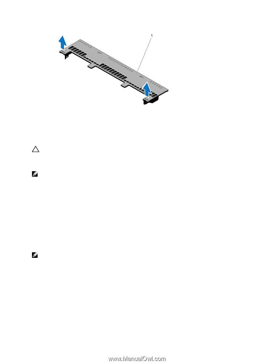
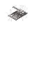
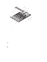
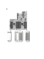
Figure 14. Removing and Installing the Cooling Shroud 1. cooling shroud Installing The Cooling Shroud CAUTION: Many repairs may only be done by a certified service technician. You should only perform troubleshooting and simple repairs as authorized in your product documentation, or as directed by the online or telephone service and support team. Damage due to servicing that is not authorized by Dell is not covered by your warranty. Read and follow the safety instructions that came with the product. NOTE: For proper seating of the cooling shroud in the chassis, ensure that the cables inside the system are routed along the chassis wall and secured using the cable securing bracket. 1. Align the tabs on the cooling shroud with the securing slots on the chassis. 2. Lower the cooling shroud into the chassis until it is firmly seated. 3. If applicable, replace the full-length PCIe card. 4. Close the system. 5. Reconnect the system to its electrical outlet and turn the system on, including any attached peripherals. System Memory Your system supports DDR3 unbuffered ECC DIMMs (ECC UDIMMs), registered DIMMs (RDIMMs), and load reduced DIMMs (LRDIMMs). It supports DDR3 and DDR3L voltage specifications. NOTE: MT/s indicates DIMM speed in MegaTransfers per second. Memory bus operating frequency can be 1600 MT/s, 1333 MT/s, 1066 MT/s, or 800 MT/s depending on: • DIMM type (UDIMM, RDIMM, or LRDIMM) • DIMM configuration (number of ranks) • maximum frequency of the DIMMs • number of DIMMs populated per channel • DIMM operating voltage • system profile selected (for example, Performance Optimized, Custom, or Dense Configuration Optimized) • maximum supported DIMM frequency of the processors 40
-
 1
1 -
2
-
3
-
4
-
5
-
6
-
7
-
8
-
9
-
10
-
11
-
12
-
13
-
14
-
15
-
16
-
17
-
18
-
19
-
20
-
21
-
22
-
23
-
24
-
25
-
26
-
27
-
28
-
29
-
30
-
31
-
32
-
33
-
34
-
 35
35 -
 36
36 -
 37
37 -
 38
38 -
 39
39 -
 40
40 -
 41
41 -
 42
42 -
 43
43 -
 44
44 -
 45
45 -
46
-
47
-
48
-
49
-
50
-
51
-
52
-
53
-
54
-
55
-
56
-
57
-
58
-
59
-
60
-
61
-
62
-
63
-
64
-
65
-
66
-
67
-
68
-
69
-
70
-
71
-
72
-
73
-
74
-
75
-
76
-
77
-
78
-
79
-
80
-
81
-
82
-
83
-
84
-
85
-
86
-
87
-
88
-
89
-
90
-
91
-
92
-
93
-
94
-
95
-
96
-
97
-
98
-
99
-
100
-
101
-
102
-
103
-
104
-
105
-
106
-
107
-
108
-
109
-
110
-
111
-
112
-
113
-
114
-
115
-
116
-
117
-
118
-
119
-
120
-
121
-
122
-
123
-
124
-
125
-
126
-
127
-
128
-
129
-
130
-
131
-
132
-
133
 |
 |