Dell External OEMR R620 Owners Manual - Page 41
Memory Socket Locations, channel 0: slots A1, A5, and A9
 |
View all Dell External OEMR R620 manuals
Add to My Manuals
Save this manual to your list of manuals |
Page 41 highlights
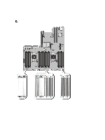
The system contains 24 memory sockets split into two sets of 12 sockets, one set per processor. Each 12-socket set is organized into four channels. In each channel, the release levers of the first socket are marked white, the second socket black, and the third socket green. NOTE: DIMMs in sockets A1 to A12 are assigned to processor 1 and DIMMs in sockets B1 to B12 are assigned to processor 2. Figure 15. Memory Socket Locations Memory channels are organized as follows: Processor 1 channel 0: slots A1, A5, and A9 channel 1: slots A2, A6, and A10 channel 2: slots A3, A7, and A11 channel 3: slots A4, A8, and A12 41
-
 1
1 -
2
-
3
-
4
-
5
-
6
-
7
-
8
-
9
-
10
-
11
-
12
-
13
-
14
-
15
-
16
-
17
-
18
-
19
-
20
-
21
-
22
-
23
-
24
-
25
-
26
-
27
-
28
-
29
-
30
-
31
-
32
-
33
-
34
-
35
-
 36
36 -
 37
37 -
 38
38 -
 39
39 -
 40
40 -
 41
41 -
 42
42 -
 43
43 -
 44
44 -
 45
45 -
 46
46 -
47
-
48
-
49
-
50
-
51
-
52
-
53
-
54
-
55
-
56
-
57
-
58
-
59
-
60
-
61
-
62
-
63
-
64
-
65
-
66
-
67
-
68
-
69
-
70
-
71
-
72
-
73
-
74
-
75
-
76
-
77
-
78
-
79
-
80
-
81
-
82
-
83
-
84
-
85
-
86
-
87
-
88
-
89
-
90
-
91
-
92
-
93
-
94
-
95
-
96
-
97
-
98
-
99
-
100
-
101
-
102
-
103
-
104
-
105
-
106
-
107
-
108
-
109
-
110
-
111
-
112
-
113
-
114
-
115
-
116
-
117
-
118
-
119
-
120
-
121
-
122
-
123
-
124
-
125
-
126
-
127
-
128
-
129
-
130
-
131
-
132
-
133
 |
 |
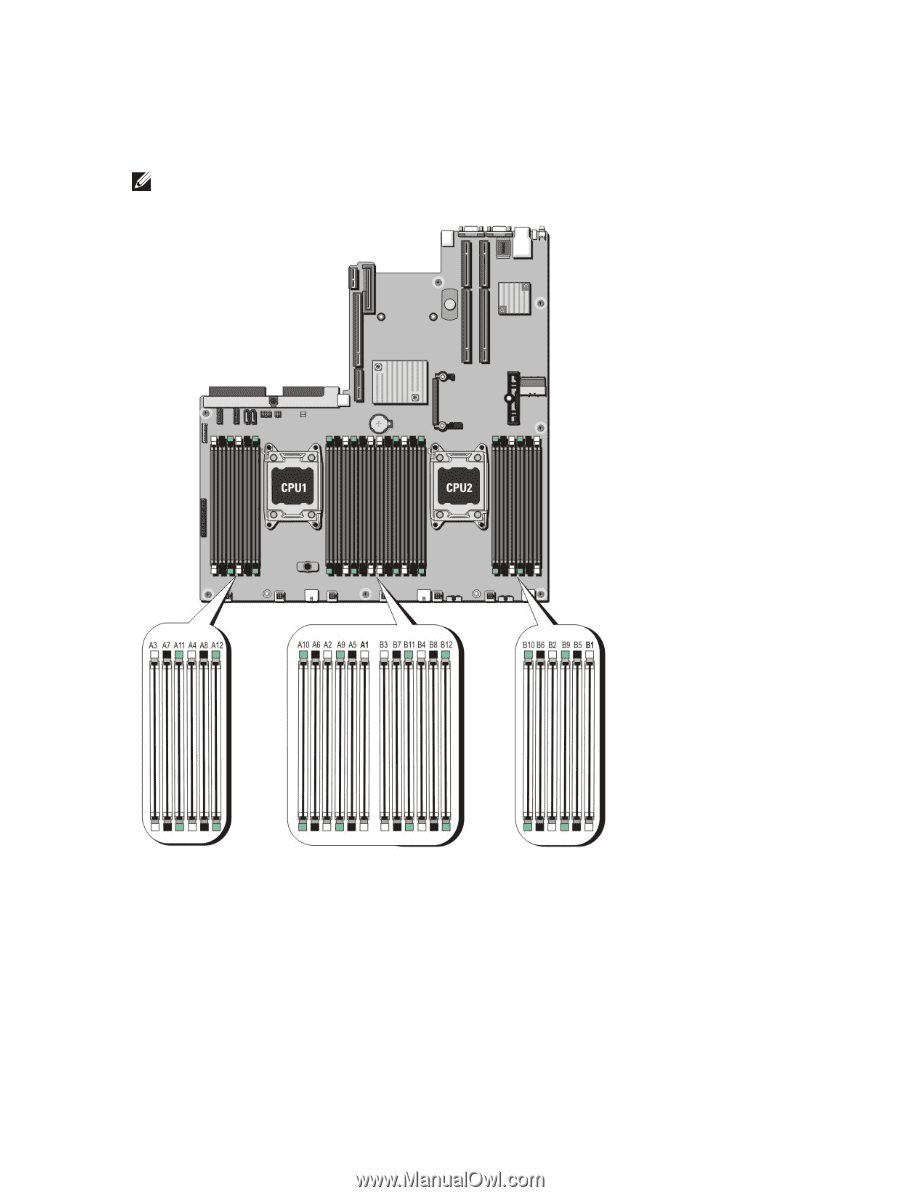
The system contains 24 memory sockets split into two sets of 12 sockets, one set per processor. Each 12-socket set is
organized into four channels. In each channel, the release levers of the first socket are marked white, the second socket
black, and the third socket green.
NOTE:
DIMMs in sockets A1 to A12 are assigned to processor 1 and DIMMs in sockets B1 to B12 are assigned to
processor 2.
Figure 15. Memory Socket Locations
Memory channels are organized as follows:
Processor 1
channel 0: slots A1, A5, and A9
channel 1: slots A2, A6, and A10
channel 2: slots A3, A7, and A11
channel 3: slots A4, A8, and A12
41