Dell External OEMR R620 Owners Manual - Page 46
Removing Memory Modules, A1, A2, A3, A4, A5, A6, A7, A8, A9
 |
View all Dell External OEMR R620 manuals
Add to My Manuals
Save this manual to your list of manuals |
Page 46 highlights
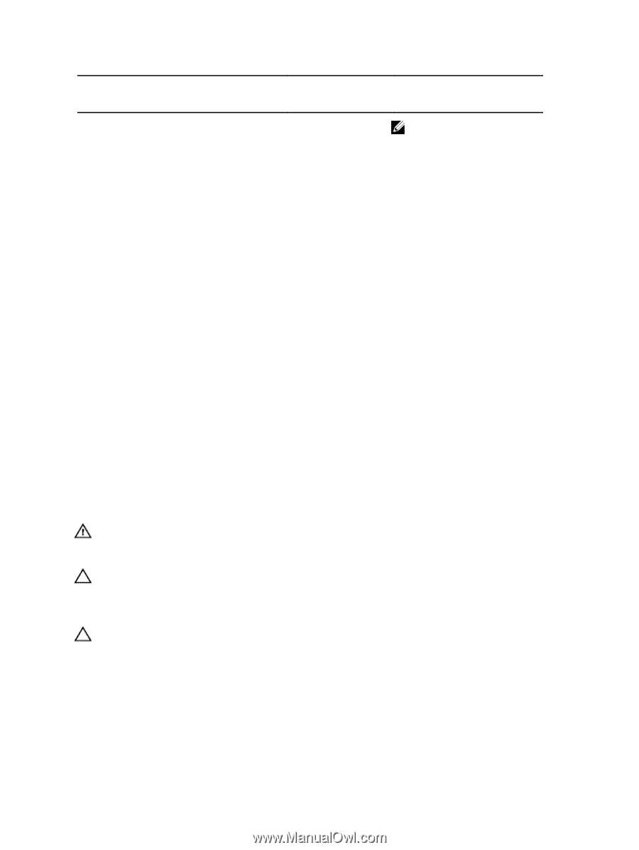
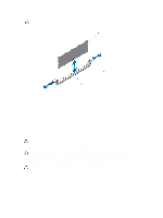
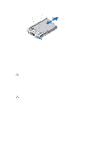
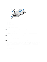
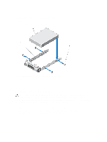
System Capacity (in GB) DIMM Size (in GB) Number of DIMMs 192 8 24 16 12 256 16 16 384 16 24 32 12 512 32 16 768 32 24 DIMM Rank, Organization, and Frequency 2R, x4, 1333 MT/s 2R, x4, 1333 MT/s, 2R, x4, 1600 MT/s 2R, x4, 1333 MT/s, 2R, x4, 1600 MT/s, 2R, x4, 1333 MT/s 4R, x4, 1333 MT/s 4R, x4, 1066 MT/s 4R, x4, 1333 MT/s LRDIMM, x4, 1333 MT/s DIMM Slot Population NOTE: 16 GB DIMMs must be installed in slots numbered A1, A2, A3, A4, B1, B2, B3, and B4 and 8 GB DIMMs must be installed in slots A5, A6, B5, and B6. A1, A2, A3, A4, A5, A6, A7, A8, A9, A10, A11, A12 B1, B2, B3, B4, B5, B6, B7, B8, B9, B10, B11, B12 A1, A2, A3, A4, A5, A6 B1, B2, B3, B4, B5, B6 A1, A2, A3, A4, A5, A6, A7, A8 B1, B2, B3, B4, B5, B6, B7, B8 A1, A2, A3, A4, A5, A6, A7, A8, A9, A10, A11, A12 B1, B2, B3, B4, B5, B6, B7, B8, B9, B10, B11, B12 A1, A2, A3, A4, A5, A6 B1, B2, B3, B4, B5, B6 A1, A2, A3, A4, A5, A6, A7, A8 B1, B2, B3, B4, B5, B6, B7, B8 A1, A2, A3, A4, A5, A6, A7, A8, A9, A10, A11, A12 B1, B2, B3, B4, B5, B6, B7, B8, B9, B10, B11, B12 Removing Memory Modules WARNING: The memory modules are hot to the touch for some time after the system has been powered down. Allow time for the memory modules to cool before handling them. Handle the memory modules by the card edges and avoid touching the components on the memory module. CAUTION: Many repairs may only be done by a certified service technician. You should only perform troubleshooting and simple repairs as authorized in your product documentation, or as directed by the online or telephone service and support team. Damage due to servicing that is not authorized by Dell is not covered by your warranty. Read and follow the safety instructions that came with the product. CAUTION: To ensure proper system cooling, memory-module blanks must be installed in any memory socket that is not occupied. Remove memory-module blanks only if you intend to install memory in those sockets. 1. Turn off the system, including any attached peripherals, and disconnect the system from the electrical outlet and peripherals. 2. Open the system. 3. Remove the cooling shroud. 4. Locate the appropriate memory module socket(s). 46
-
 1
1 -
2
-
3
-
4
-
5
-
6
-
7
-
8
-
9
-
10
-
11
-
12
-
13
-
14
-
15
-
16
-
17
-
18
-
19
-
20
-
21
-
22
-
23
-
24
-
25
-
26
-
27
-
28
-
29
-
30
-
31
-
32
-
33
-
34
-
35
-
36
-
37
-
38
-
39
-
40
-
 41
41 -
 42
42 -
 43
43 -
 44
44 -
 45
45 -
 46
46 -
 47
47 -
 48
48 -
 49
49 -
 50
50 -
 51
51 -
52
-
53
-
54
-
55
-
56
-
57
-
58
-
59
-
60
-
61
-
62
-
63
-
64
-
65
-
66
-
67
-
68
-
69
-
70
-
71
-
72
-
73
-
74
-
75
-
76
-
77
-
78
-
79
-
80
-
81
-
82
-
83
-
84
-
85
-
86
-
87
-
88
-
89
-
90
-
91
-
92
-
93
-
94
-
95
-
96
-
97
-
98
-
99
-
100
-
101
-
102
-
103
-
104
-
105
-
106
-
107
-
108
-
109
-
110
-
111
-
112
-
113
-
114
-
115
-
116
-
117
-
118
-
119
-
120
-
121
-
122
-
123
-
124
-
125
-
126
-
127
-
128
-
129
-
130
-
131
-
132
-
133
 |
 |