Dell External OEMR R620 Owners Manual - Page 54
Installing A Cooling Fan, Internal USB Memory Key (Optional)
 |
View all Dell External OEMR R620 manuals
Add to My Manuals
Save this manual to your list of manuals |
Page 54 highlights
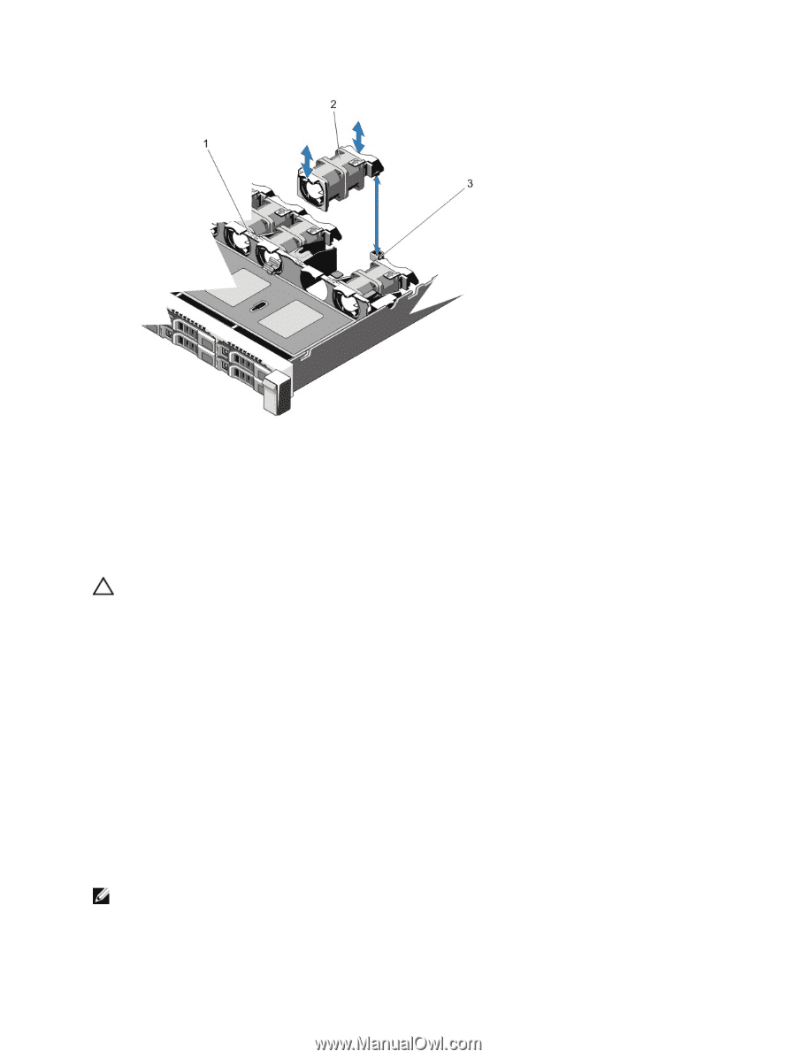
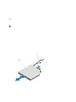
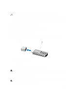
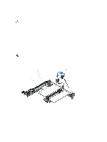
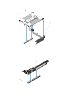
Figure 21. Removing and Installing a Cooling Fan 1. cooling fans assembly 2. cooling fans (7) 3. cooling fan connectors (7) Installing A Cooling Fan CAUTION: Many repairs may only be done by a certified service technician. You should only perform troubleshooting and simple repairs as authorized in your product documentation, or as directed by the online or telephone service and support team. Damage due to servicing that is not authorized by Dell is not covered by your warranty. Read and follow the safety instructions that came with the product. 1. Open the system. 2. Align the plug at the base of the cooling fan with the connector on the system board. 3. Slide the cooling fan into the securing slots until the tabs lock into place. 4. Close the system. Internal USB Memory Key (Optional) An optional USB memory key installed inside your system can be used as a boot device, security key, or mass storage device. The USB connector must be enabled by the Internal USB Port option in the Integrated Devices screen of the System Setup. To boot from the USB memory key, configure the USB memory key with a boot image and then specify the USB memory key in the boot sequence in the System Setup. NOTE: To locate the internal USB connector (J_USB_INT) on the system board, see System Board Connectors. 54
-
 1
1 -
2
-
3
-
4
-
5
-
6
-
7
-
8
-
9
-
10
-
11
-
12
-
13
-
14
-
15
-
16
-
17
-
18
-
19
-
20
-
21
-
22
-
23
-
24
-
25
-
26
-
27
-
28
-
29
-
30
-
31
-
32
-
33
-
34
-
35
-
36
-
37
-
38
-
39
-
40
-
41
-
42
-
43
-
44
-
45
-
46
-
47
-
48
-
 49
49 -
 50
50 -
 51
51 -
 52
52 -
 53
53 -
 54
54 -
 55
55 -
 56
56 -
 57
57 -
 58
58 -
 59
59 -
60
-
61
-
62
-
63
-
64
-
65
-
66
-
67
-
68
-
69
-
70
-
71
-
72
-
73
-
74
-
75
-
76
-
77
-
78
-
79
-
80
-
81
-
82
-
83
-
84
-
85
-
86
-
87
-
88
-
89
-
90
-
91
-
92
-
93
-
94
-
95
-
96
-
97
-
98
-
99
-
100
-
101
-
102
-
103
-
104
-
105
-
106
-
107
-
108
-
109
-
110
-
111
-
112
-
113
-
114
-
115
-
116
-
117
-
118
-
119
-
120
-
121
-
122
-
123
-
124
-
125
-
126
-
127
-
128
-
129
-
130
-
131
-
132
-
133
 |
 |