Dell External OEMR R620 Owners Manual - Page 66
Installing The Network Daughter Card, Processors
 |
View all Dell External OEMR R620 manuals
Add to My Manuals
Save this manual to your list of manuals |
Page 66 highlights
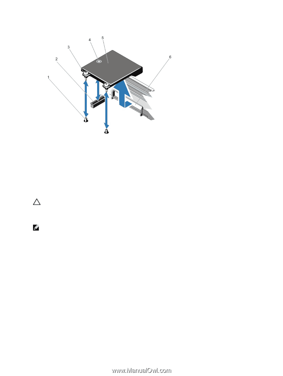
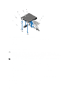
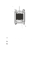
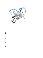
Figure 28. Removing and Installing the Network Daughter Card 1. captive screw sockets (2) 2. connector on the system board 3. captive screws (2) 4. touch point 5. network daughter card 6. back panel slots for RJ-45 connectors Installing The Network Daughter Card CAUTION: Many repairs may only be done by a certified service technician. You should only perform troubleshooting and simple repairs as authorized in your product documentation, or as directed by the online or telephone service and support team. Damage due to servicing that is not authorized by Dell is not covered by your warranty. Read and follow the safety instructions that came with the product. NOTE: If you are installing the 10 Gb network daughter card, ensure that you install the network daughter card cooling shroud in your system. 1. Angle the card so that the RJ-45 connectors fit through the slot in the back panel. 2. Align the captive screws at back-end of the card with the screw holes on the system board. 3. Press the touch point on the card to ensure that connector on the card is in contact with the connector on the system board. 4. Using a #2 Phillips screwdriver, tighten the two captive screws to secure the network daughter card to the system board. 5. Install the expansion-card riser 3. 6. Close the system. 7. Reconnect the system to its electrical outlet and turn the system on, including any attached peripherals. Processors Use the following procedure when: 66
-
 1
1 -
2
-
3
-
4
-
5
-
6
-
7
-
8
-
9
-
10
-
11
-
12
-
13
-
14
-
15
-
16
-
17
-
18
-
19
-
20
-
21
-
22
-
23
-
24
-
25
-
26
-
27
-
28
-
29
-
30
-
31
-
32
-
33
-
34
-
35
-
36
-
37
-
38
-
39
-
40
-
41
-
42
-
43
-
44
-
45
-
46
-
47
-
48
-
49
-
50
-
51
-
52
-
53
-
54
-
55
-
56
-
57
-
58
-
59
-
60
-
 61
61 -
 62
62 -
 63
63 -
 64
64 -
 65
65 -
 66
66 -
 67
67 -
 68
68 -
 69
69 -
 70
70 -
 71
71 -
72
-
73
-
74
-
75
-
76
-
77
-
78
-
79
-
80
-
81
-
82
-
83
-
84
-
85
-
86
-
87
-
88
-
89
-
90
-
91
-
92
-
93
-
94
-
95
-
96
-
97
-
98
-
99
-
100
-
101
-
102
-
103
-
104
-
105
-
106
-
107
-
108
-
109
-
110
-
111
-
112
-
113
-
114
-
115
-
116
-
117
-
118
-
119
-
120
-
121
-
122
-
123
-
124
-
125
-
126
-
127
-
128
-
129
-
130
-
131
-
132
-
133
 |
 |