Dell External OEMR R620 Owners Manual - Page 70
Installing A Processor, Removing and Installing a Processor
 |
View all Dell External OEMR R620 manuals
Add to My Manuals
Save this manual to your list of manuals |
Page 70 highlights
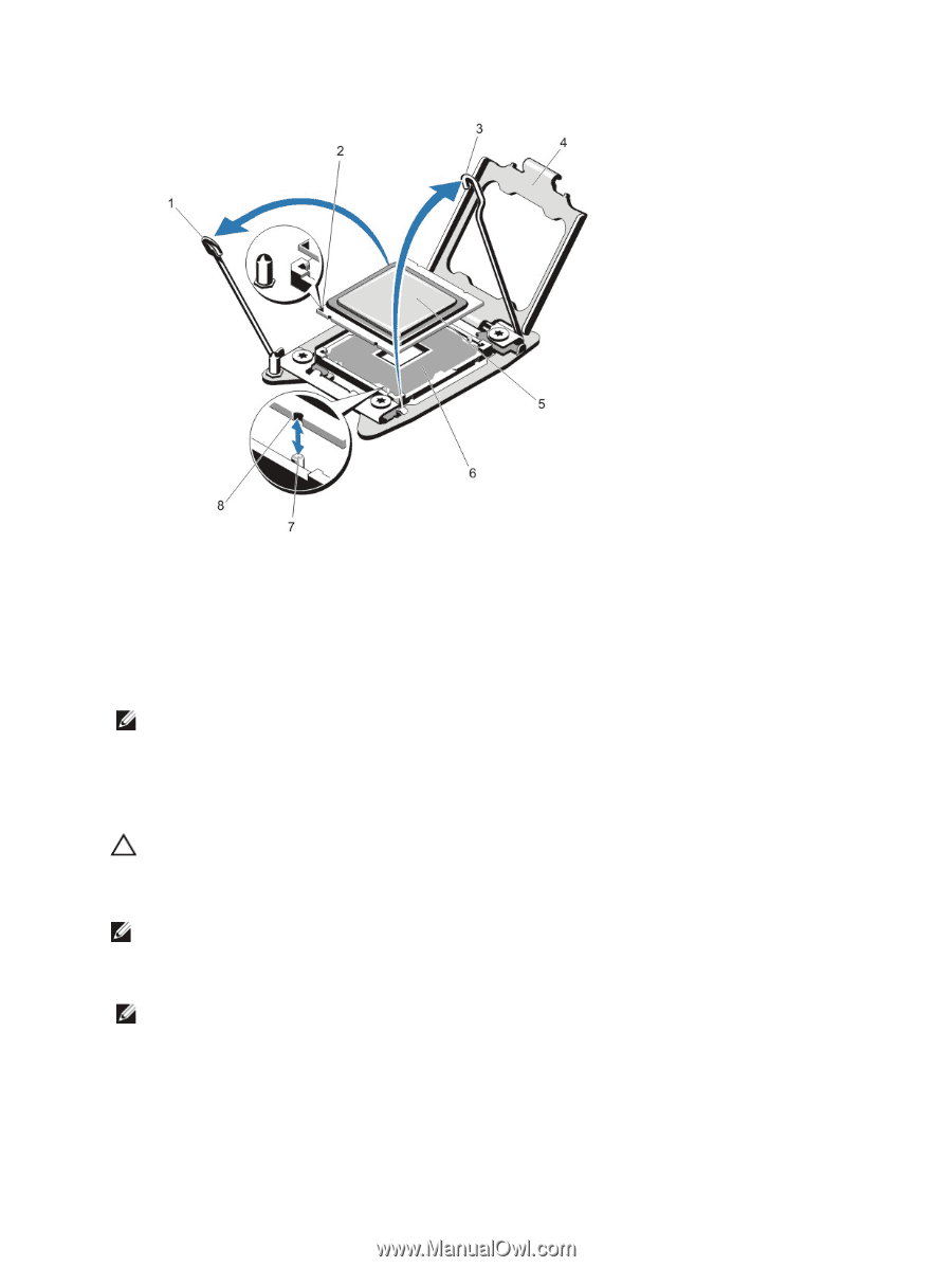
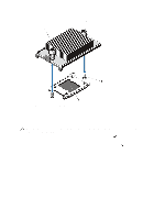
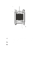
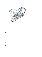
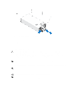
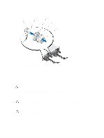
Figure 31. Removing and Installing a Processor 1. processor socket-release lever 2. pin 1 indicator 3. processor socket-release lever 4. processor shield 5. processor 6. ZIF socket 7. socket keys (4) 8. notches in processor (4) NOTE: After removing the processor, place it in an antistatic container for reuse, return, or temporary storage. Do not touch the bottom of the processor. Touch only the side edges of the processor. If you are removing the processor from processor socket 2, you must install a heat-sink blank in the empty socket. Installing A Processor CAUTION: Many repairs may only be done by a certified service technician. You should only perform troubleshooting and simple repairs as authorized in your product documentation, or as directed by the online or telephone service and support team. Damage due to servicing that is not authorized by Dell is not covered by your warranty. Read and follow the safety instructions that came with the product. NOTE: If you are installing a single processor, it must be installed in socket CPU1. 1. Before upgrading your system, download the latest system BIOS version from support.dell.com and follow the instructions included in the compressed download file to install the update on your system. NOTE: You can update the system BIOS using the Lifecycle Controller. 2. Turn off the system, including any attached peripherals, and disconnect the system from the electrical outlet. When disconnected from the power source, press and hold the power button for three seconds to fully drain the system of stored power prior to removing the cover. 70
-
 1
1 -
2
-
3
-
4
-
5
-
6
-
7
-
8
-
9
-
10
-
11
-
12
-
13
-
14
-
15
-
16
-
17
-
18
-
19
-
20
-
21
-
22
-
23
-
24
-
25
-
26
-
27
-
28
-
29
-
30
-
31
-
32
-
33
-
34
-
35
-
36
-
37
-
38
-
39
-
40
-
41
-
42
-
43
-
44
-
45
-
46
-
47
-
48
-
49
-
50
-
51
-
52
-
53
-
54
-
55
-
56
-
57
-
58
-
59
-
60
-
61
-
62
-
63
-
64
-
 65
65 -
 66
66 -
 67
67 -
 68
68 -
 69
69 -
 70
70 -
 71
71 -
 72
72 -
 73
73 -
 74
74 -
 75
75 -
76
-
77
-
78
-
79
-
80
-
81
-
82
-
83
-
84
-
85
-
86
-
87
-
88
-
89
-
90
-
91
-
92
-
93
-
94
-
95
-
96
-
97
-
98
-
99
-
100
-
101
-
102
-
103
-
104
-
105
-
106
-
107
-
108
-
109
-
110
-
111
-
112
-
113
-
114
-
115
-
116
-
117
-
118
-
119
-
120
-
121
-
122
-
123
-
124
-
125
-
126
-
127
-
128
-
129
-
130
-
131
-
132
-
133
 |
 |