Dell External OEMR R620 Owners Manual - Page 80
Hard-Drive Backplane, Removing The Hard-Drive Backplane
 |
View all Dell External OEMR R620 manuals
Add to My Manuals
Save this manual to your list of manuals |
Page 80 highlights
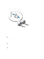
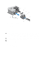
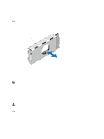
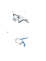
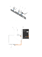
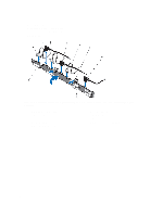
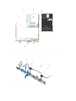
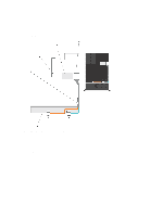
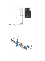
6. To install a new system battery, hold the battery with the "+" facing up and slide it under the securing tabs at the positive side of the connector. 7. Press the battery straight down into the connector until it snaps into place. 8. Align the back of the system battery cover with the notch on the network daughter card cooling shroud and push the system battery cover down into the notches till it snaps into place. 9. Close the system. 10. Reconnect the system to the electrical outlet and turn the system on, including any attached peripherals 11. Enter System Setup to confirm that the battery is operating properly. 12. Enter the correct time and date in the System Setup's Time and Date fields. 13. Exit System Setup. Hard-Drive Backplane Depending on your configuration, 8-Hard Drive System Supports 2.5 inch (x8) SAS/SATA backplane or 2.5 inch (x4) SAS/SATA backplane or 2.5 inch (x4) SAS/SATA and 2.5 inch (x2) Dell PowerEdge Express Flash (PCIe SSD) backplane 10-Hard Drive System Supports 2.5 inch (x10) SAS/SATA backplane Removing The Hard-Drive Backplane CAUTION: Many repairs may only be done by a certified service technician. You should only perform troubleshooting and simple repairs as authorized in your product documentation, or as directed by the online or telephone service and support team. Damage due to servicing that is not authorized by Dell is not covered by your warranty. Read and follow the safety instructions that came with the product. 1. If installed, remove the front bezel. 2. Turn off the system, including any attached peripherals, and disconnect the system from the electrical outlet. 3. Open the system. CAUTION: To prevent damage to the hard drives and hard-drive backplane, you must remove the hard drives from the system before removing the hard-drive backplane. CAUTION: You must note the number of each hard drive and temporarily label them before removal so that you can replace them in the same locations. 4. Remove all hard drives. 5. Disconnect the SAS/SATA/SSD data cable(s) and power cable from the backplane. 6. If applicable, disconnect the power/data cable from the optical drive. 7. Push the backplane blue release tabs in the direction of the arrows and lift the backplane upwards. 8. Pull the backplane away from the system until the securing slots on the backplane are free from the tabs on the chassis. 80
-
 1
1 -
2
-
3
-
4
-
5
-
6
-
7
-
8
-
9
-
10
-
11
-
12
-
13
-
14
-
15
-
16
-
17
-
18
-
19
-
20
-
21
-
22
-
23
-
24
-
25
-
26
-
27
-
28
-
29
-
30
-
31
-
32
-
33
-
34
-
35
-
36
-
37
-
38
-
39
-
40
-
41
-
42
-
43
-
44
-
45
-
46
-
47
-
48
-
49
-
50
-
51
-
52
-
53
-
54
-
55
-
56
-
57
-
58
-
59
-
60
-
61
-
62
-
63
-
64
-
65
-
66
-
67
-
68
-
69
-
70
-
71
-
72
-
73
-
74
-
 75
75 -
 76
76 -
 77
77 -
 78
78 -
 79
79 -
 80
80 -
 81
81 -
 82
82 -
 83
83 -
 84
84 -
 85
85 -
86
-
87
-
88
-
89
-
90
-
91
-
92
-
93
-
94
-
95
-
96
-
97
-
98
-
99
-
100
-
101
-
102
-
103
-
104
-
105
-
106
-
107
-
108
-
109
-
110
-
111
-
112
-
113
-
114
-
115
-
116
-
117
-
118
-
119
-
120
-
121
-
122
-
123
-
124
-
125
-
126
-
127
-
128
-
129
-
130
-
131
-
132
-
133
 |
 |