Dell External OEMR R620 Owners Manual - Page 83
Cabling Diagram-Systems With the 2.5 Inch x4 SAS and x2 PCIe SSD Hard-Drive Backplane
 |
View all Dell External OEMR R620 manuals
Add to My Manuals
Save this manual to your list of manuals |
Page 83 highlights
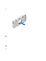
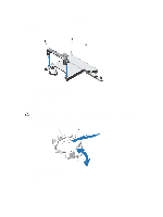
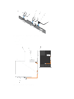
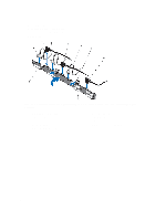
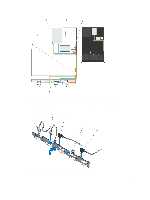
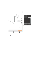
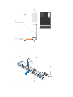
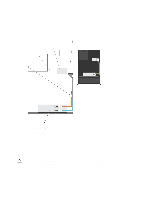
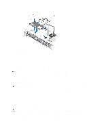
Figure 42. Cabling Diagram-Systems With the 2.5 Inch (x4 SAS and x2 PCIe SSD) Hard-Drive Backplane 1. cable retention bracket 2. system board 3. PCIe SSD card 4. integrated SAS controller card 5. SAS connector on system board 6. SAS and PCIe SSD backplane Figure 43. Removing and Installing the 2.5 Inch (x8) Hard-Drive Backplane 83
-
 1
1 -
2
-
3
-
4
-
5
-
6
-
7
-
8
-
9
-
10
-
11
-
12
-
13
-
14
-
15
-
16
-
17
-
18
-
19
-
20
-
21
-
22
-
23
-
24
-
25
-
26
-
27
-
28
-
29
-
30
-
31
-
32
-
33
-
34
-
35
-
36
-
37
-
38
-
39
-
40
-
41
-
42
-
43
-
44
-
45
-
46
-
47
-
48
-
49
-
50
-
51
-
52
-
53
-
54
-
55
-
56
-
57
-
58
-
59
-
60
-
61
-
62
-
63
-
64
-
65
-
66
-
67
-
68
-
69
-
70
-
71
-
72
-
73
-
74
-
75
-
76
-
77
-
 78
78 -
 79
79 -
 80
80 -
 81
81 -
 82
82 -
 83
83 -
 84
84 -
 85
85 -
 86
86 -
 87
87 -
 88
88 -
89
-
90
-
91
-
92
-
93
-
94
-
95
-
96
-
97
-
98
-
99
-
100
-
101
-
102
-
103
-
104
-
105
-
106
-
107
-
108
-
109
-
110
-
111
-
112
-
113
-
114
-
115
-
116
-
117
-
118
-
119
-
120
-
121
-
122
-
123
-
124
-
125
-
126
-
127
-
128
-
129
-
130
-
131
-
132
-
133
 |
 |
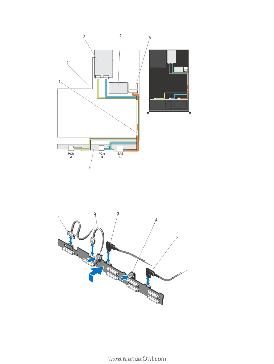
Figure 42. Cabling Diagram—Systems With the 2.5 Inch (x4 SAS and x2 PCIe SSD) Hard-Drive Backplane
1. cable retention bracket
2. system board
3. PCIe SSD card
4. integrated SAS controller card
5. SAS connector on system board
6. SAS and PCIe SSD backplane
Figure 43. Removing and Installing the 2.5 Inch (x8) Hard-Drive Backplane
83