Dell External OEMR R620 Owners Manual - Page 87
Control Panel Assembly, Removing The Control Panel Board—8 Hard Drive System
 |
View all Dell External OEMR R620 manuals
Add to My Manuals
Save this manual to your list of manuals |
Page 87 highlights
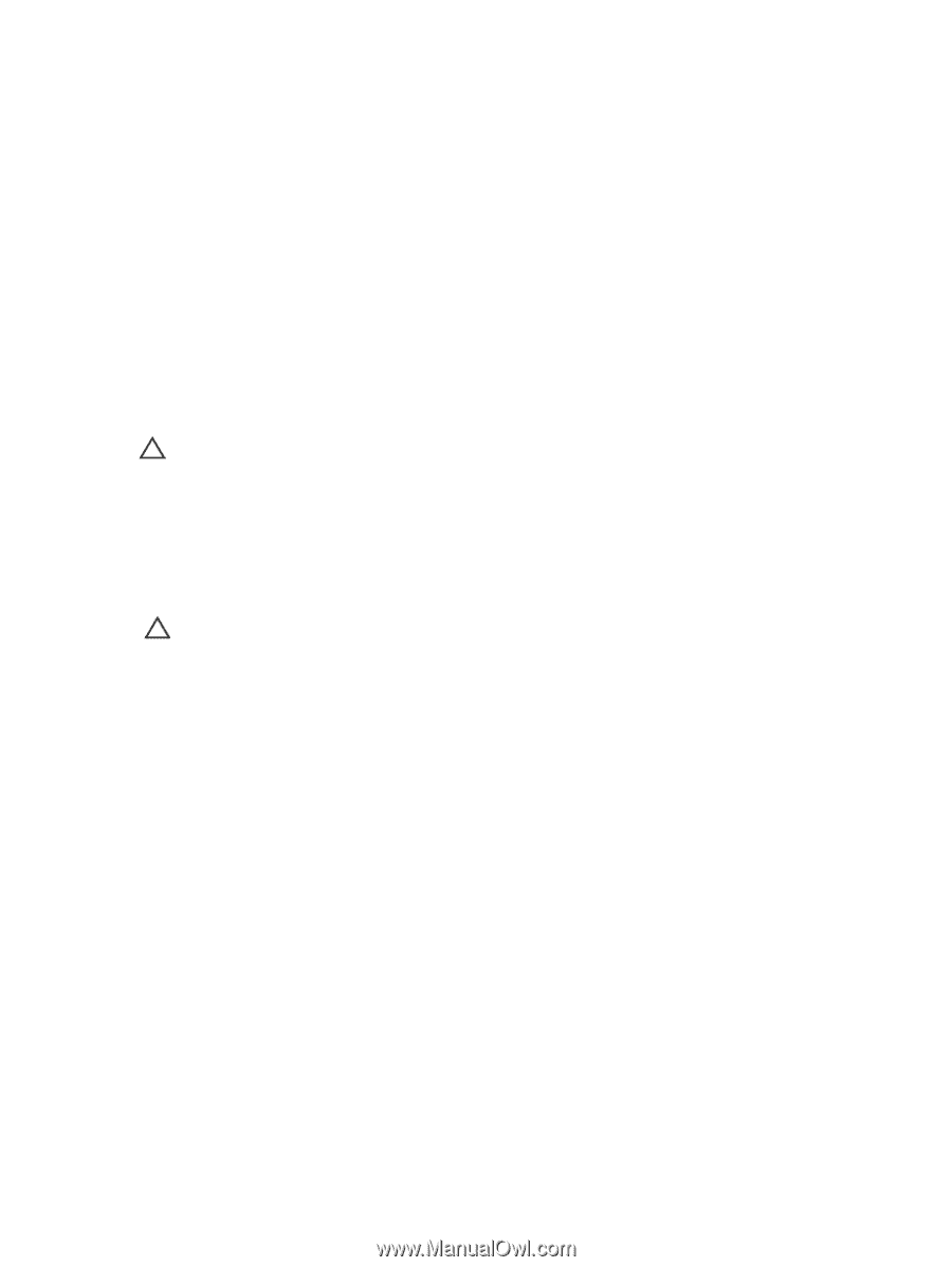
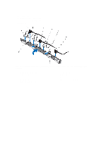
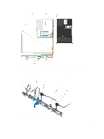
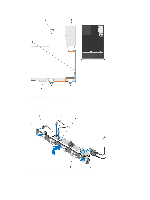
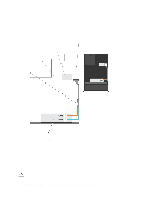
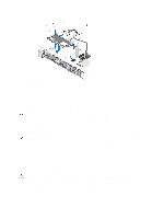
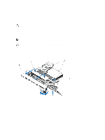
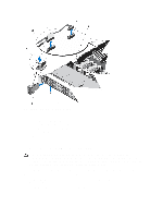
1. Holding the blue tabs, align the slots on the hard-drive backplane with the tabs on the chassis. 2. Slide down the hard-drive backplane until the release tabs snaps into place. 3. Attach the SAS A cable to the SAS A connector on the hard-drive backplane and the SAS B cable to the SAS B connector. 4. Connect the power cable(s) to the hard-drive backplane. 5. Route the power/data cables along the chassis wall. 6. Install the hard drives in their original locations. 7. Close the system. 8. Reconnect the system to its electrical outlet and turn the system on, including any attached peripherals. 9. If applicable, install the front bezel. Control Panel Assembly Removing The Control Panel Board-8 Hard Drive System CAUTION: Many repairs may only be done by a certified service technician. You should only perform troubleshooting and simple repairs as authorized in your product documentation, or as directed by the online or telephone service and support team. Damage due to servicing that is not authorized by Dell is not covered by your warranty. Read and follow the safety instructions that came with the product. 1. If installed, remove the front bezel. 2. Turn off the system, including any attached peripherals, and disconnect the system from the electrical outlet and peripherals. 3. Open the system. CAUTION: The display module connector is a ZIF (zero insertion force) connector. Ensure that the locking tab on the connector is released before removal and insertion. The locking tab must be engaged after insertion. 4. Disconnect the control panel and display module cables from the control panel board. 5. Using a #2 Phillips screwdriver, remove the two screws that secure the control panel board to the chassis. 6. Slide the control panel board toward the back and out of the system. 87
-
 1
1 -
2
-
3
-
4
-
5
-
6
-
7
-
8
-
9
-
10
-
11
-
12
-
13
-
14
-
15
-
16
-
17
-
18
-
19
-
20
-
21
-
22
-
23
-
24
-
25
-
26
-
27
-
28
-
29
-
30
-
31
-
32
-
33
-
34
-
35
-
36
-
37
-
38
-
39
-
40
-
41
-
42
-
43
-
44
-
45
-
46
-
47
-
48
-
49
-
50
-
51
-
52
-
53
-
54
-
55
-
56
-
57
-
58
-
59
-
60
-
61
-
62
-
63
-
64
-
65
-
66
-
67
-
68
-
69
-
70
-
71
-
72
-
73
-
74
-
75
-
76
-
77
-
78
-
79
-
80
-
81
-
 82
82 -
 83
83 -
 84
84 -
 85
85 -
 86
86 -
 87
87 -
 88
88 -
 89
89 -
 90
90 -
 91
91 -
 92
92 -
93
-
94
-
95
-
96
-
97
-
98
-
99
-
100
-
101
-
102
-
103
-
104
-
105
-
106
-
107
-
108
-
109
-
110
-
111
-
112
-
113
-
114
-
115
-
116
-
117
-
118
-
119
-
120
-
121
-
122
-
123
-
124
-
125
-
126
-
127
-
128
-
129
-
130
-
131
-
132
-
133
 |
 |