Dell External OEMR R620 Owners Manual - Page 90
Installing The Control Panel—8 Hard Drive System, Turn off the system
 |
View all Dell External OEMR R620 manuals
Add to My Manuals
Save this manual to your list of manuals |
Page 90 highlights
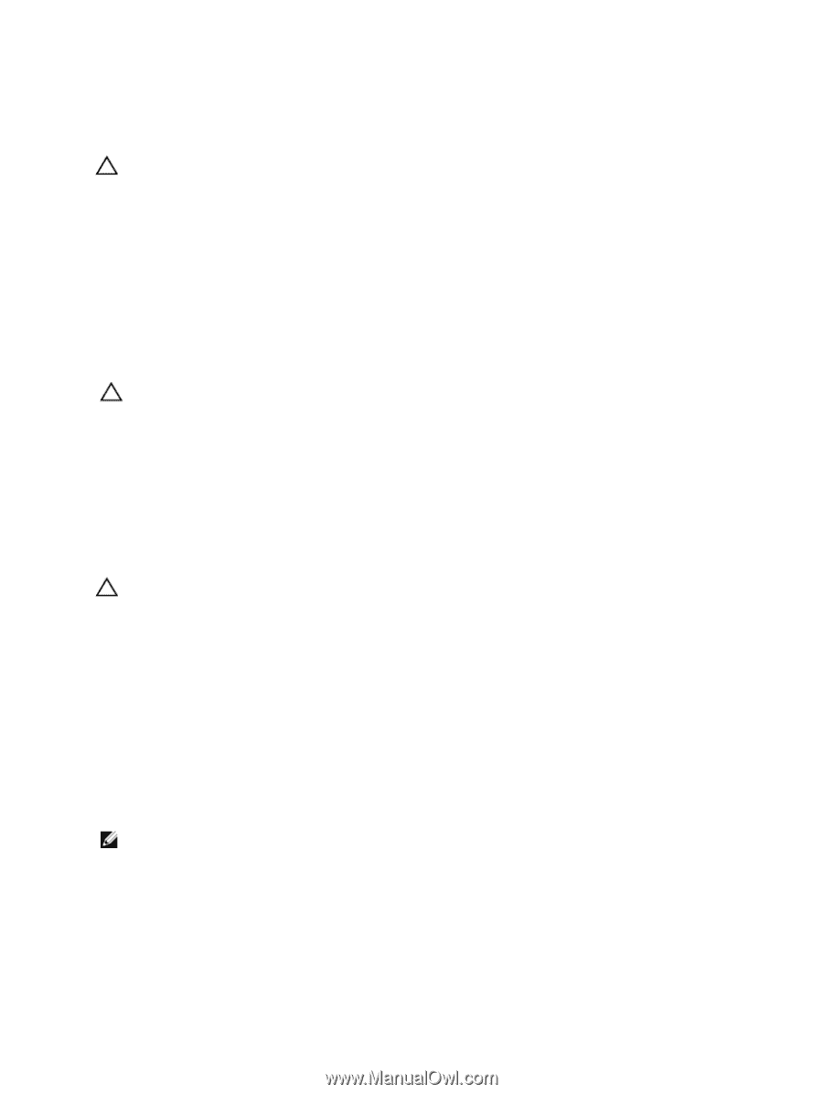
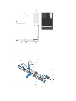
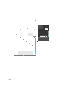
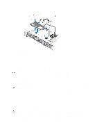
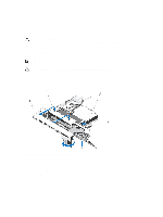
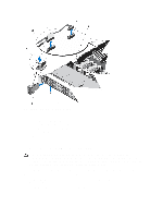
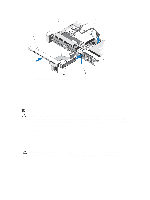
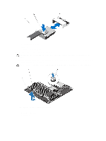
Installing The Control Panel-8 Hard Drive System CAUTION: Many repairs may only be done by a certified service technician. You should only perform troubleshooting and simple repairs as authorized in your product documentation, or as directed by the online or telephone service and support team. Damage due to servicing that is not authorized by Dell is not covered by your warranty. Read and follow the safety instructions that came with the product. 1. Slide the left side of the control panel into the chassis so that the left tab on the control panel aligns with the slot on the chassis wall and the top left tab aligns with the slot on the top of the chassis. 2. Pull the display module cable through the opening and into the chassis. 3. Push the right side of the control panel until the top right tab aligns with the top of the chassis and the panel snaps into place. 4. Using a #1 Philips screwdriver, replace the screw (located at the bottom of the chassis) that secures the control module to the chassis. CAUTION: The display module connector is a ZIF (zero insertion force) connector. Ensure that the locking tab on the connector is released before removal and insertion. The locking tab must be engaged after insertion. 5. Connect the display module cable to the control panel board. 6. Close the system. 7. If applicable, install the front bezel. 8. Reconnect the system to its electrical outlet and turn the system on, including any attached peripherals. Removing The Control Panel-10 Hard Drive System CAUTION: Many repairs may only be done by a certified service technician. You should only perform troubleshooting and simple repairs as authorized in your product documentation, or as directed by the online or telephone service and support team. Damage due to servicing that is not authorized by Dell is not covered by your warranty. Read and follow the safety instructions that came with the product. 1. If installed, remove the front bezel. 2. Turn off the system, including any attached peripherals, and disconnect the system from the electrical outlet and peripherals. 3. Open the system. 4. Using a #1 Philips screwdriver, remove the screw (located at the bottom of the chassis) that secures the control panel to the chassis. 5. Remove the control panel cable from the connectors on the system board (J_CP and J_FP_USB) and the hard-drive expander card. NOTE: To locate the connectors on the system board, see System Board Connectors. 6. Press the control panel latch and slide the control panel out of the chassis. 7. Disconnect the control panel cable from the control panel. 90
-
 1
1 -
2
-
3
-
4
-
5
-
6
-
7
-
8
-
9
-
10
-
11
-
12
-
13
-
14
-
15
-
16
-
17
-
18
-
19
-
20
-
21
-
22
-
23
-
24
-
25
-
26
-
27
-
28
-
29
-
30
-
31
-
32
-
33
-
34
-
35
-
36
-
37
-
38
-
39
-
40
-
41
-
42
-
43
-
44
-
45
-
46
-
47
-
48
-
49
-
50
-
51
-
52
-
53
-
54
-
55
-
56
-
57
-
58
-
59
-
60
-
61
-
62
-
63
-
64
-
65
-
66
-
67
-
68
-
69
-
70
-
71
-
72
-
73
-
74
-
75
-
76
-
77
-
78
-
79
-
80
-
81
-
82
-
83
-
84
-
 85
85 -
 86
86 -
 87
87 -
 88
88 -
 89
89 -
 90
90 -
 91
91 -
 92
92 -
 93
93 -
 94
94 -
 95
95 -
96
-
97
-
98
-
99
-
100
-
101
-
102
-
103
-
104
-
105
-
106
-
107
-
108
-
109
-
110
-
111
-
112
-
113
-
114
-
115
-
116
-
117
-
118
-
119
-
120
-
121
-
122
-
123
-
124
-
125
-
126
-
127
-
128
-
129
-
130
-
131
-
132
-
133
 |
 |