Dell Force10 MXL Blade Getting Started Guide
Dell Force10 MXL Blade Manual
 |
View all Dell Force10 MXL Blade manuals
Add to My Manuals
Save this manual to your list of manuals |
Dell Force10 MXL Blade manual content summary:
- Dell Force10 MXL Blade | Getting Started Guide - Page 1
Dell Force10 MXL 10/40GbE Switch IO Module Getting Started Guide June 2012 Regulatory Model: DF10MXL - Dell Force10 MXL Blade | Getting Started Guide - Page 2
of Dell Inc. Intel®, Pentium®, Xeon®, Core™ and Celeron® are registered trademarks of Intel Corporation in the U.S. and other countries. AMD® is a registered trademark and AMD Opteron™, AMD Phenom™, and AMD Sempron™ are trademarks of Advanced Micro Devices, Inc. Microsoft®, Windows®, Windows Server - Dell Force10 MXL Blade | Getting Started Guide - Page 3
Panel 6 Base Module 7 FlexIOTM Plug-in Modules 7 Port Numbering 9 USB Ports 10 System and Port LEDs 11 Installation 13 Unpacking the Switch 14 4 Installing and Configuring the Switch. . . 14 Installing the Switch Blade in a PowerEdge M1000e . 16 Connecting a Console Terminal 18 Contents 3 - Dell Force10 MXL Blade | Getting Started Guide - Page 4
and U-Boot CLIs 19 Performing the Initial Configuration 19 5 Assembling a Switch Stack 25 Configuring and Bringing Up a Stack 26 Managing a Stack 28 6 Splitting 40GbE QSFP+ Ports into 10GbE SFP+ Ports 30 7 Switch Configuration 31 DCB Support 32 FCoE Connectivity 32 iSCSI Operation 32 - Dell Force10 MXL Blade | Getting Started Guide - Page 5
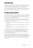
the initial configuration. For more detailed information about any of the basic installation steps, refer to the Dell PowerEdge M1000e Enclosure Owner's Manual on the Dell Support website at http://support.dell.com/manuals. Product Description The MXL 10/40GbE Switch is a layer 2/3 blade switch with - Dell Force10 MXL Blade | Getting Started Guide - Page 6
contains information about device characteristics and modular hardware configurations for the MXL 10/40GbE Switch. Internal Ports The MXL 10/40GbE Switch provides 32 1/10-Gigabit Ethernet internal ports. The internal ports are connected to server blades through the M1000e chassis midplane. Each port - Dell Force10 MXL Blade | Getting Started Guide - Page 7
In addition, you can configure the native 40GbE ports as stacking ports. You can connect up to six MXL 10/40GbE Switches (in the same or cables NOTE: The 10Mb speed is not supported on the 4-Port 10GBASE-T module. Only 100Mb, 1GbE, and 10GbE speeds are supported. • 2-Port 40-Gigabit Ethernet quad - Dell Force10 MXL Blade | Getting Started Guide - Page 8
On the MXL 10/40GbE Switch, you can configure uplink ports of the same speed on different modules in the same link aggregation group (LAG). You can also use individual ports for uplink connections. NOTE: A maximum of 16 ports are supported in a LAG. For switch stacking, you must use a 40GbE port on - Dell Force10 MXL Blade | Getting Started Guide - Page 9
Port Numbering When installed in a PowerEdge M1000e Enclosure, the MXL 10/40GbE Switch ports are numbered 33 to 56 from the bottom to the top of the switch: • 40GbE base-module ports: • In 40GbE mode of operation, the ports are numbered 33 and 37. • In 4x10GbE mode of operation, the ports are - Dell Force10 MXL Blade | Getting Started Guide - Page 10
connectors). The console port supports asynchronous data of eight data bits, one stop bit, no parity bit, and no flow control. The default baud rate is 9600 bps. The upper USB port functions as an external flash drive that you can use to store configuration files and scripts. 10 Hardware Overview - Dell Force10 MXL Blade | Getting Started Guide - Page 11
System and Port LEDs The front panel of the MXL 10/40GbE Switch contains light emitting diodes (LEDs) that provide information about the status of the switch (Figure 1-4). Figure 1-4. System LEDs on Front Panel 40GbE Ports System Status LED System Power LED Table 1-1 describes system LED - Dell Force10 MXL Blade | Getting Started Guide - Page 12
describes the LED status of the 10GbE BASE-T, 10GbE SFP+, and 40GbE QSFP+ ports. Table 1-2. Port LED Status Port LED Color Off 10G. The port is up and is transmitting traffic at lower than maximum speed: A 40GbE QSFP+ port is transmitting at 10G. A 10GbE SFP+ or 10GBASE-T port is transmitting - Dell Force10 MXL Blade | Getting Started Guide - Page 13
ports using a 4x10G breakout cable. Table 1-3. LED Status of a 40GbE QSFP+ Port with Breakout Cable Port LED Link Status Color Off Yellow , and fluorescent lighting fixtures. • Ambient Temperature - The ambient switch operating temperature range is 10° to 35ºC (50° to 95ºF). NOTE: Decrease the - Dell Force10 MXL Blade | Getting Started Guide - Page 14
, make sure that the following items are included: • One Dell Force10 MXL 10/40GbE Switch IO Module • One USB type A-to-DB-9 female cable • Getting Started Guide • Safety and Regulatory Information • Warranty and Support Information • Software License Agreement Unpacking Steps NOTE: Before unpacking - Dell Force10 MXL Blade | Getting Started Guide - Page 15
Figure 1-6. MXL 10/40GbE Switch: Installation and Configuration Flow Chart Insert Switch Blade and Power On Connect Console Yes X-Loader CLI Run Memory Tests/ Yes Configure Switch Settings Reboot Press any key to enter X-Loader or U-Boot menu? No Do not press a key U-Boot CLI No Do not press - Dell Force10 MXL Blade | Getting Started Guide - Page 16
management controllers Server blades are installed in the front of the chassis (Figure 1-7); switch blades are installed in the back of the chassis (Figure 1-8). Figure 1-7. PowerEdge M1000e: Front View with Server Blades 16 half-height server blades 16 Installing and Configuring the Switch - Dell Force10 MXL Blade | Getting Started Guide - Page 17
slide the MXL 10/40GbE Switch in so that the connectors on the back of the blade touch the chassis midplane, the switch receives power from the chassis and automatically powers on. The chassis management controller (CMC) in the chassis validates that the switch blade is a supported I/O module before - Dell Force10 MXL Blade | Getting Started Guide - Page 18
Console Terminal After the MXL 10/40GbE Switch powers on, complete all external cabling connections and connect a terminal to the blade to configure the switch. NOTE: If you are installing a stack of MXL 10/40GbE Switches, connect the terminal to the console port on the Master Switch. If you connect - Dell Force10 MXL Blade | Getting Started Guide - Page 19
perform the initial switch configuration, make sure that: • The MXL 10/40GbE Switch was never configured before and is in the same state as when you received it. • The MXL 10/40GbE Switch booted successfully when it powered on. • The console connection was established and the Dell Easy Setup Wizard - Dell Force10 MXL Blade | Getting Started Guide - Page 20
values are applied. For more information about how to perform the initial configuration using the CLI, refer to the Dell Force10 FTOS Configuration Guide for the Dell Force10 MXL 10/40GbE Switch IO Module. This Getting Started Guide describes how to use the Easy Setup Wizard for initial - Dell Force10 MXL Blade | Getting Started Guide - Page 21
following text is displayed: Welcome to Dell Easy Setup Wizard The setup wizard guides you through the initial switch configuration, and gets you up and running as quickly as possible. You can skip the setup wizard, and enter CLI mode to manually configure the switch. You must respond to the next - Dell Force10 MXL Blade | Getting Started Guide - Page 22
". The wizard automatically assigns read/write privilege to this account. You can use Dell Network Manager or other management interfaces to change this setting, and to add additional enter the user password: ****** Please reenter the user password: ****** 22 Installing and Configuring the Switch - Dell Force10 MXL Blade | Getting Started Guide - Page 23
to access the CLI, Web interface, or SNMP interface of the switch. To access the switch through any Management Interface you can . set up the IP address for the Management Interface. . set up the default gateway if IP address is manually configured on the OOB interface. Would you like to set up the - Dell Force10 MXL Blade | Getting Started Guide - Page 24
the wizard: [Y/N] y Thank you for using the Dell Easy Setup Wizard. You will now enter CLI mode. Applying Interface configuration, please wait ... FTOS> NOTE: If you do not save the initial configuration settings, they will be lost at the next switch reboot and the Setup Wizard will be invoked. To - Dell Force10 MXL Blade | Getting Started Guide - Page 25
initial switch configuration, the MXL 10/40GbE Switch is powered up and operational. Stacking is supported on the 40GbE ports on the base module or a 2-Port 40GbE QSFP+ module to connect up to six MXL 10/40GbE Switches in a single stack. Figure 1-9 shows an example using six MXL 10/40GbE Switches in - Dell Force10 MXL Blade | Getting Started Guide - Page 26
attach the QSFP+ cables in a stack of MXL 10/40GbE Switches, to configure and bring up the stack, follow these steps: 1 Connect the terminal to the console port on an MXL 10/40GbE Switch. Enter the following commands to access the CLI and configure the two 40GbE ports on the base module for stacking - Dell Force10 MXL Blade | Getting Started Guide - Page 27
stack group, enter the show system stack-unit unit-number stack-group command. 2 Save the stacking configuration on the 40GbE ports: FTOS# write memory 3 Repeat Steps 1 and 2 on each MXL 10/40GbE Switch in the stack by entering the stack-unit 0 stack-group 0 and stack-unit 0 stack-group 1 commands - Dell Force10 MXL Blade | Getting Started Guide - Page 28
FTOS# configure FTOS(conf)# stack-unit 0 priority 14 The no form of the stack-unit unit-number priority number command reverts the management priority of a stack unit to the default value of 0. Managing a Stack Master and Member Switches You can manage a stack of MXL 10/40GbE Switches as a single - Dell Force10 MXL Blade | Getting Started Guide - Page 29
from partition a:, enter the commands: FTOS# configure FTOS(conf)# boot system stack-unit unit-number primary system a: FTOS(conf)# end FTOS# write memory FTOS# power-cycle stack-unit unit-number NOTE: When an MXL 10/40GbE Switch is stacked, booting is supported only from flash memory; it is not - Dell Force10 MXL Blade | Getting Started Guide - Page 30
stacks was previously a member switch, the last saved configuration on the original stack is used to configure the new stack. Splitting 40GbE QSFP+ Ports into 10GbE SFP+ Ports The MXL 10/40GbE Switch supports splitting a 40GbE port on the base module or a 2-Port 40GbE QSFP+ module into four 10GbE - Dell Force10 MXL Blade | Getting Started Guide - Page 31
optimization • IGMP snooping • RADIUS support • TACACS+ client For information about how to configure switch software, refer to the User's Configuration Guide for the Dell Force10 MXL 10/40 GbE Switch IO Module on the Dell Support website at http://support.dell.com/manuals. Switch Configuration 31 - Dell Force10 MXL Blade | Getting Started Guide - Page 32
a MXL 10/40GbE Switch, the internal ports of the MXL 10/40GbE Switch support FCoE connectivity and connect to the converged network adapter (CNA) in blade servers. FCoE allows Fiber Channel to use 10-Gigabit Ethernet networks while preserving the Fiber Channel protocol. You must manually configure - Dell Force10 MXL Blade | Getting Started Guide - Page 33
.aspx For information about how to configure stacking, refer to the User's Configuration Guide for the Dell Force10 MXL 10/40 GbE Switch IO Module on the Dell Support website at http://support.dell.com/manuals. • You can customize the MXL 10/40GbE Switch for use in your data center - Dell Force10 MXL Blade | Getting Started Guide - Page 34
Technical Specifications The MXL 10/40GbE Switch is an I/O module and installed with Server (model: PowerEdge M1000e) for communication. according to manufacturer's instructions. Chassis Physical Design Parameter Height Width Depth Specifications 1.32 inches (33.45 mm) 10.81 inches (274.75 - Dell Force10 MXL Blade | Getting Started Guide - Page 35
@ 200/40 VAC 123 Watts MTBF 355,178 hours IEEE Standards The MXL 10/40GbE Switch complies with the following IEEE standards: • 802.1AB LLDP • 802. Extensions for VLAN Tagging • 802.3ad Link Aggregation with LACP • 802.3ae 10 Gigabit Ethernet (10GBASE-X) • 802.3ba 40 Gigabit Ethernet (40GBase-SR4, - Dell Force10 MXL Blade | Getting Started Guide - Page 36
36 Technical Specifications - Dell Force10 MXL Blade | Getting Started Guide - Page 37
- Dell Force10 MXL Blade | Getting Started Guide - Page 38
Printed in the U.S.A. www.dell.com | support.dell.com
-
 1
1 -
 2
2 -
 3
3 -
 4
4 -
 5
5 -
 6
6 -
 7
7 -
8
-
9
-
10
-
11
-
12
-
13
-
14
-
15
-
16
-
17
-
18
-
19
-
20
-
21
-
22
-
23
-
24
-
25
-
26
-
27
-
28
-
29
-
30
-
31
-
32
-
33
-
34
-
35
-
36
-
37
-
38
 |
 |

Dell Force10 MXL 10/40GbE
Switch IO Module
Getting Started Guide
June 2012
Regulatory Model: DF10MXL