Dell Force10 S2410-01-10GE-24P Dell Force10 S2410 System Quick Start Guide
Dell Force10 S2410-01-10GE-24P Manual
 |
View all Dell Force10 S2410-01-10GE-24P manuals
Add to My Manuals
Save this manual to your list of manuals |
Dell Force10 S2410-01-10GE-24P manual content summary:
- Dell Force10 S2410-01-10GE-24P | Dell Force10 S2410 System Quick Start Guide - Page 1
Dell Force10 S2410 System Quick Start Guide Regulatory Model: S2410P/S2410CP - Dell Force10 S2410-01-10GE-24P | Dell Force10 S2410 System Quick Start Guide - Page 2
- Dell Force10 S2410-01-10GE-24P | Dell Force10 S2410 System Quick Start Guide - Page 3
Dell Force10 S2410 System Quick Start Guide Regulatory Model: S2410P/S2410CP - Dell Force10 S2410-01-10GE-24P | Dell Force10 S2410 System Quick Start Guide - Page 4
: A CAUTION indicates potential damage to hardware or loss of data if instructions are not followed. WARNING: A WARNING indicates a potential for property damage, personal injury, or death. If you purchased a Dell n Series computer, any references in this publication to Microsoft Windows operating - Dell Force10 S2410-01-10GE-24P | Dell Force10 S2410 System Quick Start Guide - Page 5
and configuration information, refer to the following documents: Documentation S2410 Hardware installation and power-up Installing the S2410 System instructions Software configuration SFTOS Configuration Guide for the S2410 Command line interface SFTOS Command Line Reference Latest updates - Dell Force10 S2410-01-10GE-24P | Dell Force10 S2410 System Quick Start Guide - Page 6
2 About this Guide - Dell Force10 S2410-01-10GE-24P | Dell Force10 S2410 System Quick Start Guide - Page 7
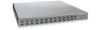
guide assumes all site preparation has been performed before installing the chassis. Installing the S2410 Chassis in a Rack or Cabinet There are two models of the S2410 switch labeled 10/100 Ethernet). To install the S2410 system, Dell Force10 recommends that you complete the installation procedures - Dell Force10 S2410-01-10GE-24P | Dell Force10 S2410 System Quick Start Guide - Page 8
for attaching the rack ears. Longer screws might compromise the electronics. Shorter or weaker screws might not adequately support the S2410. 2 Attach the ears to the front corners of the switch. 752-00350-00 Installing on Rack Ensure that your equipment rack is earth ground. The equipment rack - Dell Force10 S2410-01-10GE-24P | Dell Force10 S2410 System Quick Start Guide - Page 9
Dell Force10 recommends that one person hold the S2410 chassis in place while a second person attaches the brackets to the posts. 2 Position the S2410 the system (no on/off switch). Supplying Power to the System NOTE: The power cords shipped by default with the S2410 chassis are for the United - Dell Force10 S2410-01-10GE-24P | Dell Force10 S2410 System Quick Start Guide - Page 10
2 Connecting either power cord to power starts the system. There is no on/off switch. NOTE: The AC receptacles are labeled A and B, matched to the PSU A and PSU B status LEDs on the face of the S2410. Labeling the power cords A and B can help in a diagnostic situation. Fans Fan replacement is - Dell Force10 S2410-01-10GE-24P | Dell Force10 S2410 System Quick Start Guide - Page 11
cables can result in interface errors, and Dell Force10 will not support applications using non-qualified cabling. NOTE: The S2410 CX4 ports auto-sense the length of the attached cable, so their pre-emphasis does not need to be set manually. Required CX4 Cable Housing Clearances The maximum - Dell Force10 S2410-01-10GE-24P | Dell Force10 S2410 System Quick Start Guide - Page 12
to the long axis of the trapezoidal nozzle. Accessing XFP Ports Dell Force10 offers various types of XFP transceivers. For details, see: the S2410CP includes four XFP ports. The XFP transceiver (not included in the S2410 chassis shipping box) is a small rectangular module that you insert into the - Dell Force10 S2410-01-10GE-24P | Dell Force10 S2410 System Quick Start Guide - Page 13
in the closed position, as shown here. For details on XFP installation, see the instruction that accompanies the XFP. 2 Insert the XFP gently into the port until it Dell Force10 branded devices are at the following URL: http://www.force10networks.com/products/mediaspecifications.asp S2410 - Dell Force10 S2410-01-10GE-24P | Dell Force10 S2410 System Quick Start Guide - Page 14
Parameter S2410P Width 17 inches (432 mm) Depth 16.73 inches (425 mm) Chassis weight with factory-installed components 12 pounds (5.5 kg) Rack clearance required Front: 5-inches (12.7 cm) Rear: 5-inches (12.7 cm) S2410CP 17 inches (432 mm) 16.73 inches (425 mm) 12 pounds (5.5 kg) Front: 5- - Dell Force10 S2410-01-10GE-24P | Dell Force10 S2410 System Quick Start Guide - Page 15
Parameter S2410P Maximum Current Draw S2410P: 2.05 A @ 100/120 VAC, 1.025 A @ 200/240 VAC Maximum Power Consumption S2410P: 225W (3.5W per XFP) S2410CP S2410CP: 1.5 A @ 100/120 VAC, .575 A @ 200/240 VAC S2410CP: 125W Installing the Hardware 11 - Dell Force10 S2410-01-10GE-24P | Dell Force10 S2410 System Quick Start Guide - Page 16
12 Installing the Hardware - Dell Force10 S2410-01-10GE-24P | Dell Force10 S2410 System Quick Start Guide - Page 17
7, pin 3 to pin 6, pin 4 to pin 5, and the inverse for pins 5 through 8. If necessary, connect the RJ-45/DB-9 adapter that is shipped with the S2410 system to the end of the RJ-45 cable that will connect to your terminal. Installing the Software 13 - Dell Force10 S2410-01-10GE-24P | Dell Force10 S2410 System Quick Start Guide - Page 18
connection, you can modify the settings to match at each end of the connection. 3 If you use the console port to download software to the switch, you will probably want to raise the console baud rate. Establish a connection with the default settings to verify the connection. Then use the lineconfig - Dell Force10 S2410-01-10GE-24P | Dell Force10 S2410 System Quick Start Guide - Page 19
to any Ethernet port in your network through which you can access the switch via a Telnet, SSH, SNMP, or Web client. For details on configuring the port (setting up an IP address to it) for management access, refer to the SFTOS Configuration Guide for the S2410. Default Configuration A version of - Dell Force10 S2410-01-10GE-24P | Dell Force10 S2410 System Quick Start Guide - Page 20
interface. ip address ipaddr subnetmask (Config-if-ma)# prompt within the Global Config mode NOTE: Creating a management IP address is supported by both the Layer 2 (Switching) and Layer 3 (Routing) licenses of SFTOS. By default, the management address is reachable from all ports on the default - Dell Force10 S2410-01-10GE-24P | Dell Force10 S2410 System Quick Start Guide - Page 21
what software is installed. To assign an IP address to an interface, use the following commands: Step Task Command Syntax 1 Enables routing for the switch. ip routing 2 Configures an IP address on an ip address interface. The IP address may be a secondary IP address. Command Mode Global Config - Dell Force10 S2410-01-10GE-24P | Dell Force10 S2410 System Quick Start Guide - Page 22
Global Config mode NOTE: Creating a management IP address is supported by both the Layer 2 (Switching) and Layer 3 (Routing) licenses of SFTOS. By default password (commonly called the "enable" password), is not set when the S2410 starts for the first time. To set the enable password, access the - Dell Force10 S2410-01-10GE-24P | Dell Force10 S2410 System Quick Start Guide - Page 23
Port The S2410 supports the Ethernet Management port (labeled 10/100 Ethernet and commonly called the service port). It is a dedicated management port (in addition to the console port and the virtual management port). You can use the service port to access the switch through Telnet, SSH, TFTP - Dell Force10 S2410-01-10GE-24P | Dell Force10 S2410 System Quick Start Guide - Page 24
Setting the IP Address of the Virtual Management Port If you want to access the switch through Telnet, SSH, TFTP, or the SFTOS Web UI, you must set up the service port to configure an IP address that is accessible, by default, through ports in VLAN 1. You can also do both with separate - Dell Force10 S2410-01-10GE-24P | Dell Force10 S2410 System Quick Start Guide - Page 25
spanning-tree Config spanning-tree port mode Config enable all Create a Port-based VLAN When you set up a management IP address, you can manage the switch through any enabled port in VLAN1. By default, the management VLAN is set up on the default VLAN 1, and includes all ports. The default VLAN - Dell Force10 S2410-01-10GE-24P | Dell Force10 S2410 System Quick Start Guide - Page 26
: You must have the optional SFTOS Layer 3 Package installed to configure routing commands and to set IP addressing an interface. Refer to the SFTOS Configuration Guide for information on implementing the Layer 3 capabilities. 22 Installing the Software - Dell Force10 S2410-01-10GE-24P | Dell Force10 S2410 System Quick Start Guide - Page 27
Step Task Command Syntax 1 Enables routing for the switch. ip routing 2 Configures an IP address on an ip address interface the S2410 to the Network Once you have completed the hardware installation and software configuration for the S2410, you can connect to your company network by following - Dell Force10 S2410-01-10GE-24P | Dell Force10 S2410 System Quick Start Guide - Page 28
24 Installing the Software - Dell Force10 S2410-01-10GE-24P | Dell Force10 S2410 System Quick Start Guide - Page 29
- Dell Force10 S2410-01-10GE-24P | Dell Force10 S2410 System Quick Start Guide - Page 30
Printed in the U.S.A. www.dell.com | support.dell.com
-
 1
1 -
 2
2 -
 3
3 -
 4
4 -
 5
5 -
 6
6 -
 7
7 -
8
-
9
-
10
-
11
-
12
-
13
-
14
-
15
-
16
-
17
-
18
-
19
-
20
-
21
-
22
-
23
-
24
-
25
-
26
-
27
-
28
-
29
-
30
 |
 |
Dell Force10
S2410 System
Quick Start Guide
Regulatory Model:
S2410P/S2410CP