Dell Force10 S2410-01-10GE-24P Installing the S2410 System
Dell Force10 S2410-01-10GE-24P Manual
 |
View all Dell Force10 S2410-01-10GE-24P manuals
Add to My Manuals
Save this manual to your list of manuals |
Dell Force10 S2410-01-10GE-24P manual content summary:
- Dell Force10 S2410-01-10GE-24P | Installing the S2410 System - Page 1
Installing the S2410 System - Dell Force10 S2410-01-10GE-24P | Installing the S2410 System - Page 2
damage to hardware or loss of data if instructions are not followed. WARNING: A WARNING indicates a potential for property damage, personal injury, or death. Information in this publication is subject to change without notice. © 2010 Dell Force10. All rights reserved. Reproduction of these materials - Dell Force10 S2410-01-10GE-24P | Installing the S2410 System - Page 3
Contents 1 About this Guide Information Symbols and Warnings 5 Related Publications 6 2 The S2410 System Physical Interfaces 7 Required Equipment 7 Features 8 Ports 8 System Status 9 LED Displays 9 3 Site Preparation Site Selection 11 Cabinet Placement 11 Rack Mounting 12 Fans and Airflow - Dell Force10 S2410-01-10GE-24P | Installing the S2410 System - Page 4
and Compliance Agency Certifications 29 Electromagnetic Compatibility (EMC 30 Product Recycling and Disposal 30 7 Technical Support The iSupport Website 33 Accessing iSupport Services 33 Contacting the Technical Assistance Center 34 Locating Serial Numbers 34 Requesting a Hardware Replacement - Dell Force10 S2410-01-10GE-24P | Installing the S2410 System - Page 5
and power-up of the S2410, refer to the SFTOS™ Configuration Guide for the S2410 for software configuration information and the SFTOS Command Reference, Version 2.4 for detailed Command Line Interface (CLI) information. NOTE: S2410 switches contain no user-serviceable parts. For details on recycling - Dell Force10 S2410-01-10GE-24P | Installing the S2410 System - Page 6
www.dell.com | support.dell.com Related Publications For more information about the S2410, refer to the following documents: • SFTOS Configuration Guide, Version 2.4.1 • SFTOS Command Reference, Version 2.4.1 • S2410 Quick Reference • S-Series and SFTOS Version 2.4.1 Release Notes Each of these - Dell Force10 S2410-01-10GE-24P | Installing the S2410 System - Page 7
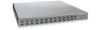
8 • System Status on page 9 Physical Interfaces The Dell Force10 S2410 is a Layer 2 switch that is available in two models - the S2410CP and 19 A AL L 20 21 A AL L 22 S2410-01-10GE-24CP 23 System Alarm 10/100 Ethernet PSU-A 24 PSU-B Console Status LEDs Console Port Figure 2-2. ) The - Dell Force10 S2410-01-10GE-24P | Installing the S2410 System - Page 8
www.dell.com | support.dell.com • At least one cable (included) to connect the power source to the S2410 AC power supply • Brackets and screws ( • 24 line-rate 10 GbE ports (See Ports for details.) • CPU and switch processor • Flash memory • Standard 1U chassis height by 19-inch rack-mountable width - Dell Force10 S2410-01-10GE-24P | Installing the S2410 System - Page 9
S2410 Quick Reference, the SFTOS Command Reference (SFTOS 2.4), and the SFTOS Configuration Guide (SFTOS 2.4). LED Displays As shown in Figure 2-1 on page 7, the S2410 Management Port (labeled 10/100 Ethernet) (commonly called the service port) Description Link LED (upper left side of each port - Dell Force10 S2410-01-10GE-24P | Installing the S2410 System - Page 10
10 | The S2410 System www.dell.com | support.dell.com - Dell Force10 S2410-01-10GE-24P | Installing the S2410 System - Page 11
Power on page 12 • Storing Components on page 12 • Tools Required on page 13 For detailed S2410 specifications, refer to Chapter , S2410 Specifications, on page 27. NOTE: Install the S2410 into a rack or cabinet before installing any optional components. Site Selection Make sure that the area where - Dell Force10 S2410-01-10GE-24P | Installing the S2410 System - Page 12
www.dell.com | support.dell.com Rack Mounting Ensure that your equipment rack is earth ground. The equipment rack must be grounded to the same ground point used by the power service in your area. The ground path must be permanent. For rack-mounting instructions, see Rack or Cabinet Installation on - Dell Force10 S2410-01-10GE-24P | Installing the S2410 System - Page 13
dry surface or floor, away from direct sunlight, heat, and air conditioning ducts. • Store in a dust-free environment. Tools Required S-Series switches are shipped fully assembled, encased in foam. A utility knife is useful for cutting the packing tape, and a #2 Phillips screwdriver is required for - Dell Force10 S2410-01-10GE-24P | Installing the S2410 System - Page 14
14 | Site Preparation www.dell.com | support.dell.com - Dell Force10 S2410-01-10GE-24P | Installing the S2410 System - Page 15
S2410 S2410 and its components. Tabletop Installation The S2410 S2410 (see Chassis Physical Design on page 27). • Position the S2410 so that there is proper side ventilation (see Fans and Airflow on page 12). • Position the S2410 The S2410 provides Ears The S2410 is shipped the switch before - Dell Force10 S2410-01-10GE-24P | Installing the S2410 System - Page 16
www.dell.com | support.dell.com 752-00350-00 The lower right corner of Figure 4-1 shows the positioning of the rack ears and screws. Note that the rack ears supplied with the S2410 have a hole in the middle to accommodate the vent in the S2410. Figure 4-1. Attaching Rack Ears to Switch Two-Post - Dell Force10 S2410-01-10GE-24P | Installing the S2410 System - Page 17
rack ears first, using only the supplied screws (see Attaching the Rack Ears on page 15), and then follow the steps below to install the S2410 chassis into a four-post 19-inch equipment rack, using the attached front mounting brackets and the optional adjustable rear-mounting brackets. Step Task - Dell Force10 S2410-01-10GE-24P | Installing the S2410 System - Page 18
www.dell.com | support.dell.com Step Task 2 Insert the S2410 into the rack, and secure the chassis to the front post with two screws. Then secure the chassis with the four screws. Figure 4-5. Four-post Rack-mounting with Adjustable Rear-mounting Brackets, Step 3 18 | Installing the S2410 - Dell Force10 S2410-01-10GE-24P | Installing the S2410 System - Page 19
nuts. Step Task 1 Attach the two rear brackets to the side panels. Align the three holes in the bracket with the three holes on the S2410 chassis, and secure the brackets to the chassis using the screws. Figure 4-6. Four-post Rack-mounting with Cage Nuts, Step 1 Top View of Brackets Align - Dell Force10 S2410-01-10GE-24P | Installing the S2410 System - Page 20
www.dell.com | support.dell.com Step Task 4 Position the cage nuts over the holes on each bracket flange and each rack post. Figure 4-8. Four-post Rack through to the holes in the rack post. Figure 4-9. Four-post Rack-mounting with Cage Nuts, Step 5 fn00147e_s50 20 | Installing the S2410 - Dell Force10 S2410-01-10GE-24P | Installing the S2410 System - Page 21
S2410 is unique among S-Series switches in several aspects: • It has no stacking functionality. • It has a dedicated Ethernet Management port (commonly called the service S2410 Quick Reference or the Getting Started chapter of the SFTOS Configuration Guide (SFTOS 2.4.1.0). Installing the S2410 | 21 - Dell Force10 S2410-01-10GE-24P | Installing the S2410 System - Page 22
22 | Installing the S2410 www.dell.com | support.dell.com - Dell Force10 S2410-01-10GE-24P | Installing the S2410 System - Page 23
S2410 Quick Reference or the Getting Started chapter of the SFTOS Configuration Guide for the S2410. Connect the RJ-45/DB-9 adapter that is shipped with the S2410 Figure 5-1. S2410 Console Port Set your initial console terminal settings to match the default console settings on the switch: • 9600 - Dell Force10 S2410-01-10GE-24P | Installing the S2410 System - Page 24
data sheet: http://www.force10networks.com/products/s2410.asp Dell Force10 has tested each of the listed cables over all environmental conditions. Use of unqualified cables can result in interface errors, and Dell Force10 will not support applications using non-qualified cabling. For more detail - Dell Force10 S2410-01-10GE-24P | Installing the S2410 System - Page 25
to the long axis of the trapezoidal nozzle. Accessing XFP Ports Dell Force10 offers various types of XFP transceivers. For details, see: the S2410CP includes four XFP ports. The XFP transceiver (not included in the S2410 chassis shipping box) is a small rectangular module (see Figure 5-3 on page - Dell Force10 S2410-01-10GE-24P | Installing the S2410 System - Page 26
.dell.com | support.dell. position, as shown here. For details on XFP installation, see the instruction that accompanies the XFP. fn00101-S2410WT 2 Insert the XFP gently into the transceiver with an optical power meter. Generally, Dell Force10 specified optics are not to be subjected to receive - Dell Force10 S2410-01-10GE-24P | Installing the S2410 System - Page 27
6 S2410 Specifications Chassis Physical Design Parameter Height Width Depth Weight (with factory-installed components) Rack Clearance Required Specifications Standard 1U STD-810 Telcordia GR-63-CORE S2410CP: 61.5 dBA at 73.4°F (23°C) S2410P: 61.5 dBA at 73.4°F (23°C) S2410 Specifications | 27 - Dell Force10 S2410-01-10GE-24P | Installing the S2410 System - Page 28
States relating to electromagnetic compatibility. Force 10 Networks can not accept responsibility for any failure to satisfy the protection requirements resulting from a non-recommended modification of this product, including the fitting of non-Dell Force10 option cards. This product has been tested - Dell Force10 S2410-01-10GE-24P | Installing the S2410 System - Page 29
Dell Force10 trouble occurs, the user may be required to take corrective actions. WARNING: AC Power cords are for use with Dell Force10 equipment only. Do not use Dell Force10 Laser Products-Part 1: Equipment Classification Requirements and User's Guide • EN 60825-2 Safety of Laser Products-Part 2: - Dell Force10 S2410-01-10GE-24P | Installing the S2410 System - Page 30
dell.com | support.dell for Network services in several countries to assist equipment owners in recycling their IT products. Waste Electrical and Electronic Equipment (WEEE) Directive for Recovery, Recycle and Reuse of IT and Telecommunications Products Dell Force10 switches S2410 Specifications - Dell Force10 S2410-01-10GE-24P | Installing the S2410 System - Page 31
Dell Force10 product recycling offerings, see the WEEE Recycling instructions on iSupport at: http://www.force10networks.com/CSPortal20/Support/WEEEandRecycling.pdf. For more information, contact the Dell Force10 phillips screws that connect the switch cover to the body. The S2410 Specifications | 31 - Dell Force10 S2410-01-10GE-24P | Installing the S2410 System - Page 32
www.dell.com | support.dell.com Batteries or packaging hazardous substances. For proper collection and treatment, contact your local Dell Force10 representative. Figure 6-3. The European WEEE symbol For California: Perchlorate Material Practices for Perchlorate Materials. 32 | S2410 Specifications - Dell Force10 S2410-01-10GE-24P | Installing the S2410 System - Page 33
Dell Force10 equipment and mitigating the impact of network outages. Through iSupport you can obtain technical information regarding Dell Force10 • Support Programs: Information on the complete suite of Dell Force10 support and professional support services. To access some iSupport services you - Dell Force10 S2410-01-10GE-24P | Installing the S2410 System - Page 34
Contacting the Technical Assistance Center How to Contact Dell Force10 Log in to iSupport at http://www.force10networks.com/support/, and select the Service TAC Request tab. Managing Your Case Log in to iSupport, and select the Service Request tab to view all open cases and RMAs. Downloading - Dell Force10 S2410-01-10GE-24P | Installing the S2410 System - Page 35
support case. Open a support case by: • Using the Create Service Request form on the iSupport page (see Contacting the Technical Assistance Center on page 34). • Contacting Dell Force10 -support.) • Console captures showing the error messages • Console captures showing the troubleshooting steps - Dell Force10 S2410-01-10GE-24P | Installing the S2410 System - Page 36
36 | Technical Support www.dell.com | support.dell.com - Dell Force10 S2410-01-10GE-24P | Installing the S2410 System - Page 37
cable 8 console port pinouts 23 console terminal settings 23 contacting TAC (technical support) 33 CX4 connector 25 CX4 Ports, Using 24 CX4 pre-emphasis 24 D Danger 5 DB-9 to RJ-45 8 depth of chassis 27 disposal, switch 30 E earth ground 12 electromagnetic noise 11 electrostatic discharge 12, 15 - Dell Force10 S2410-01-10GE-24P | Installing the S2410 System - Page 38
9 sound level 27 sound levels 27 Specifications chassis 27 environmental 11 status information, S2410 9 status panel LEDs 7 Status, System 9 storage guidelines 12 Storing Components 12 support contacts 33 switch recycling 30 System Status 9 T Tabletop Installation 15 Technical Assistance Center (TAC - Dell Force10 S2410-01-10GE-24P | Installing the S2410 System - Page 39
U user-serviceable parts 28 Using CX4 Ports 24 Using XFP Ports 25 V ventilation 12 voltage 28 W Warning 5 Web UI 23 Web User Interface, SFTOS 9 WEEE 30, 32 width of chassis 27 X XFP Installation 25 XFP Ports, Using 25 Index | 39 - Dell Force10 S2410-01-10GE-24P | Installing the S2410 System - Page 40
40 | Index www.dell.com | support.dell.com - Dell Force10 S2410-01-10GE-24P | Installing the S2410 System - Page 41
- Dell Force10 S2410-01-10GE-24P | Installing the S2410 System - Page 42
Printed in the U.S.A. www.dell.com | support.dell.com
-
 1
1 -
 2
2 -
 3
3 -
 4
4 -
 5
5 -
 6
6 -
 7
7 -
8
-
9
-
10
-
11
-
12
-
13
-
14
-
15
-
16
-
17
-
18
-
19
-
20
-
21
-
22
-
23
-
24
-
25
-
26
-
27
-
28
-
29
-
30
-
31
-
32
-
33
-
34
-
35
-
36
-
37
-
38
-
39
-
40
-
41
-
42
 |
 |

Installing the S2410 System