Dell Inspiron 14R N4010 Inspiron 14R N4010 Service Manual
Dell Inspiron 14R N4010 Manual
 |
View all Dell Inspiron 14R N4010 manuals
Add to My Manuals
Save this manual to your list of manuals |
Dell Inspiron 14R N4010 manual content summary:
- Dell Inspiron 14R N4010 | Inspiron 14R N4010 Service Manual - Page 1
Dell™ Inspiron™ N4010 Service Manual Before You Begin Battery Module Cover Memory Module(s) Optical Drive Keyboard Palm Rest Power Button Board Coin-Cell Battery Wireless Mini-Card(s) Internal Card With Bluetooth® Wireless Technology Thermal Fan System Board Hard Drive Thermal Cooling Assembly - Dell Inspiron 14R N4010 | Inspiron 14R N4010 Service Manual - Page 2
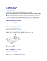
Page AC Adapter Connector Dell™ Inspiron™ N4010 Service Manual Removing the AC Adapter Connector Replacing the AC Adapter Connector ). 3. Follow the instructions from step 4 to step 15 in Removing the System Board. 4. Remove the display assembly (see Removing the Display Assembly). 5. Remove - Dell Inspiron 14R N4010 | Inspiron 14R N4010 Service Manual - Page 3
(see Replacing the Daughter Board). 5. Replace the middle cover (see Replacing the Middle Cover). 6. Replace the display assembly (see Replacing the Display Assembly). 7. Follow the instructions from step 6 to step 18 in Replacing the System Board. 8. Replace the battery (see Replacing the Battery - Dell Inspiron 14R N4010 | Inspiron 14R N4010 Service Manual - Page 4
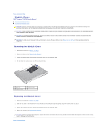
Back to Contents Page Module Cover Dell™ Inspiron™ N4010 Service Manual Removing the Module Cover Replacing the Module Cover WARNING: Before working inside your computer, read the safety information that shipped with your computer. For additional safety best practices information, see - Dell Inspiron 14R N4010 | Inspiron 14R N4010 Service Manual - Page 5
Dell™ Inspiron™ N4010 Service Manual Recommended Tools Turning Off Your Computer Before Working Inside Your Computer This manual at support.dell.com operating system: Windows® Vista: Click the Start button Windows® 7: cards with care. Do not touch the components or contacts on a card. Hold a card - Dell Inspiron 14R N4010 | Inspiron 14R N4010 Service Manual - Page 6
from the network device. 3. Disconnect all telephone or network cables from the computer. 4. Press and eject any installed cards from the 7-in-1 media card reader. 5. 8. Turn the computer top-side up, open the display, and press the power button to ground the system board. Back to Contents Page - Dell Inspiron 14R N4010 | Inspiron 14R N4010 Service Manual - Page 7
Contents Page Flashing the BIOS Dell™ Inspiron™ N4010 Service Manual 1. Turn on the computer. 2. Go to support.dell.com. 3. Click Drivers & Downloads® Select Model. 4. Locate the BIOS update file for your computer: NOTE: The Service Tag for your computer is located at the bottom of the computer. If - Dell Inspiron 14R N4010 | Inspiron 14R N4010 Service Manual - Page 8
Back to Contents Page Internal Card With Bluetooth® Wireless Technology Dell™ Inspiron™ N4010 Service Manual Removing the Bluetooth Card Replacing the Bluetooth Card WARNING: Before working inside your computer, read the safety information that shipped with your computer. For additional safety best - Dell Inspiron 14R N4010 | Inspiron 14R N4010 Service Manual - Page 9
the keyboard (see Replacing the Keyboard). 6. Replace the memory module(s) (see Replacing the Memory Module(s)). 7. Replace the module cover (see Replacing the Module Cover). 8. Follow the instructions from step 4 to step 5 in Replacing the Optical Drive. 9. Replace the battery (see Replacing the - Dell Inspiron 14R N4010 | Inspiron 14R N4010 Service Manual - Page 10
Back to Contents Page Camera Module Dell™ Inspiron™ N4010 Service Manual Removing the Camera Module Replacing the Camera Module WARNING: Before working inside your computer, read the safety information that shipped with your computer. For additional safety best practices information, see the - Dell Inspiron 14R N4010 | Inspiron 14R N4010 Service Manual - Page 11
the Display Assembly). 8. Replace the palm rest (see Replacing the Palm Rest). 9. Replace the keyboard (see Replacing the Keyboard). 10. Replace the memory module(s) (see Replacing the Memory Module(s)). 11. Replace the module cover (see Replacing the Module Cover). 12. Follow the instructions from - Dell Inspiron 14R N4010 | Inspiron 14R N4010 Service Manual - Page 12
Back to Contents Page Coin-Cell Battery Dell™ Inspiron™ N4010 Service Manual Removing the Coin-Cell Battery Replacing the Coin-Cell Battery WARNING: Before working inside your computer, read the safety information that shipped with your computer. For additional safety best practices information, - Dell Inspiron 14R N4010 | Inspiron 14R N4010 Service Manual - Page 13
8. Follow the instructions from step 4 to step 5 in Replacing the Optical Drive. 9. Replace the battery (see Replacing the Battery). CAUTION: Before turning on the computer, replace all screws and ensure that no stray screws remain inside the computer. Failure to do so may result in damage to the - Dell Inspiron 14R N4010 | Inspiron 14R N4010 Service Manual - Page 14
Back to Contents Page Processor Module Dell™ Inspiron™ N4010 Service Manual Removing the Processor Module Replacing the Processor Module WARNING: Before working inside your computer, read the safety information that shipped with your computer. For additional safety best practices information, see - Dell Inspiron 14R N4010 | Inspiron 14R N4010 Service Manual - Page 15
a new thermal pad along with documentation to illustrate proper installation. 1. Follow the instructions in Before You Begin. 2. Align the pin-1 corner of the processor module system board. 4. Replace the thermal cooling assembly (see Replacing the Thermal Cooling Assembly). Back to Contents Page - Dell Inspiron 14R N4010 | Inspiron 14R N4010 Service Manual - Page 16
Back to Contents Page Thermal Cooling Assembly Dell™ Inspiron™ N4010 Service Manual Removing the Thermal Cooling Assembly Replacing the Thermal Cooling Assembly WARNING: Before working inside your computer, read the safety information that shipped with your computer. For additional safety best - Dell Inspiron 14R N4010 | Inspiron 14R N4010 Service Manual - Page 17
- Dell Inspiron 14R N4010 | Inspiron 14R N4010 Service Manual - Page 18
Page Daughter Board Dell™ Inspiron™ N4010 Service Manual Removing the Daughter Board Replacing the Daughter Board instructions from step 4 to step 15 in Removing the System Board. 4. Remove the Mini-Card(s) (see Removing the Mini-Card(s)). 5. Remove the display assembly (see Removing the Display - Dell Inspiron 14R N4010 | Inspiron 14R N4010 Service Manual - Page 19
the Middle Cover). 5. Replace the display assembly (see Replacing the Display Assembly). 6. Replace the Mini-Card(s) (see Replacing the Mini-Card(s)). 7. Follow the instructions from step 6 to step 18 in Replacing the System Board. 8. Replace the battery (see Replacing the Battery). CAUTION: Before - Dell Inspiron 14R N4010 | Inspiron 14R N4010 Service Manual - Page 20
Back to Contents Page Display Dell™ Inspiron™ N4010 Service Manual Display Assembly Display Bezel Display Panel Display Hinges Hinge Caps WARNING: Before working inside your computer, read the safety information that shipped with your computer. For additional safety best practices information, see - Dell Inspiron 14R N4010 | Inspiron 14R N4010 Service Manual - Page 21
Rest). 9. Replace the keyboard (see Replacing the Keyboard). 10. Replace the memory module(s) (see Replacing the Memory Module(s)). 11. Replace the module cover (see Replacing the Module Cover). 12. Follow the instructions from step 4 to step 5 in Replacing the Optical Drive. 13. Replace the battery - Dell Inspiron 14R N4010 | Inspiron 14R N4010 Service Manual - Page 22
. 4. Remove the display bezel. 1 display bezel Replacing the Display Bezel 1. Follow the instructions in Before You Begin. 2. Realign the display bezel over the display panel, and gently snap into place. 3. Replace the display assembly (see Replacing the Display Assembly). Display Panel Removing the - Dell Inspiron 14R N4010 | Inspiron 14R N4010 Service Manual - Page 23
display cable. 1 display cable 2 display board connector 3 tape 4 back of the display panel 8. Remove the six screws (three on each side) that secure the display panel brackets to the display panel. 1 screws (6) 2 display panel brackets (2) Replacing the Display Panel 1. Follow the instructions - Dell Inspiron 14R N4010 | Inspiron 14R N4010 Service Manual - Page 24
caps (see Removing the Hinge Caps). Replacing the Display Hinges 1. Follow the instructions in Before You Begin. 2. Replace the hinge caps (see Replacing the Hinge Caps). 3. Route the Mini-Card antenna cables on the display hinge. 4. Align the screw hole on the display hinges with the screw hole on - Dell Inspiron 14R N4010 | Inspiron 14R N4010 Service Manual - Page 25
the instructions in Before You Begin. 2. Place the hinge caps on the display hinges and snap them into place. 3. Replace the display hinges (see Replacing the Display Hinges). 4. Replace the display panel (see Replacing the Display Panel). 5. Replace the display bezel (see Replacing the Display - Dell Inspiron 14R N4010 | Inspiron 14R N4010 Service Manual - Page 26
Back to Contents Page Thermal Fan Dell™ Inspiron™ N4010 Service Manual Removing the Thermal Fan Replacing the Thermal Fan WARNING: Before working inside your computer, read the safety information that shipped with your computer. For additional safety best practices information, see - Dell Inspiron 14R N4010 | Inspiron 14R N4010 Service Manual - Page 27
the keyboard (see Replacing the Keyboard). 6. Replace the memory module(s) (see Replacing the Memory Module(s)). 7. Replace the module cover (see Replacing the Module Cover). 8. Follow the instructions from step 4 to step 5 in Replacing the Optical Drive. 9. Replace the battery (see Replacing the - Dell Inspiron 14R N4010 | Inspiron 14R N4010 Service Manual - Page 28
Back to Contents Page Hard Drive Dell™ Inspiron™ N4010 Service Manual Removing the Hard Drive Replacing the Hard Drive WARNING: Before working inside your computer, read the safety information that shipped with your computer. For additional safety best practices information, see the Regulatory - Dell Inspiron 14R N4010 | Inspiron 14R N4010 Service Manual - Page 29
2 hard drive Replacing the Hard Drive 1. Follow the instructions in Before You Begin. 2. Remove the new drive from its packaging. Save the original packaging for storing or shipping the hard drive. 3. Align the screw holes on the hard-drive bracket with the screw holes on the hard drive and replace - Dell Inspiron 14R N4010 | Inspiron 14R N4010 Service Manual - Page 30
Back to Contents Page Middle Cover Dell™ Inspiron™ N4010 Service Manual Removing the Middle Cover Replacing the Middle Cover WARNING: Before working inside your computer, read the safety information that shipped with your computer. For additional safety best practices information, see - Dell Inspiron 14R N4010 | Inspiron 14R N4010 Service Manual - Page 31
the keyboard (see Replacing the Keyboard). 7. Replace the memory module(s) (see Replacing the Memory Module(s)). 8. Replace the module cover (see Replacing the Module Cover). 9. Follow the instructions from step 4 to step 5 in Replacing the Optical Drive. 10. Replace the battery (see Replacing the - Dell Inspiron 14R N4010 | Inspiron 14R N4010 Service Manual - Page 32
Back to Contents Page I/O Board Dell™ Inspiron™ N4010 Service Manual Removing the I/O Board Replacing the I/O Board WARNING: Before working inside your computer, read the safety information that shipped with your computer. For additional safety best practices information, see the - Dell Inspiron 14R N4010 | Inspiron 14R N4010 Service Manual - Page 33
the Display Assembly). 7. Replace the palm rest (see Replacing the Palm Rest). 8. Replace the keyboard (see Replacing the Keyboard). 9. Replace the memory module(s) (see Replacing the Memory Module(s)). 10. Replace the module cover (see Replacing the Module Cover). 11. Follow the instructions from - Dell Inspiron 14R N4010 | Inspiron 14R N4010 Service Manual - Page 34
Back to Contents Page Keyboard Dell™ Inspiron™ N4010 Service Manual Removing the Keyboard Replacing the Keyboard WARNING: Before working inside your computer, read the safety information that shipped with your computer. For additional safety best practices information, see the Regulatory Compliance - Dell Inspiron 14R N4010 | Inspiron 14R N4010 Service Manual - Page 35
10. Without pulling hard on the keyboard, hold it towards the display. 11. Lift the connector latch that secures the keyboard cable to the connector on the system board and remove the keyboard cable. 12. Lift the keyboard off the computer. 1 keyboard tabs 2 keyboard cable (5) connector Replacing - Dell Inspiron 14R N4010 | Inspiron 14R N4010 Service Manual - Page 36
9. Replace the battery (see Replacing the Battery). CAUTION: Before turning on the computer, replace all screws and ensure that no stray screws remain inside the computer. Failure to do so may result in damage to the computer. Back to Contents Page - Dell Inspiron 14R N4010 | Inspiron 14R N4010 Service Manual - Page 37
Back to Contents Page Memory Module(s) Dell™ Inspiron™ N4010 Service Manual Removing the Memory Module(s) Replacing the Memory Module(s) WARNING: Before working inside your computer, read the safety information that shipped with your computer. For additional safety best practices information, see - Dell Inspiron 14R N4010 | Inspiron 14R N4010 Service Manual - Page 38
computer and an electrical outlet. CAUTION: Before turning on the computer, replace all screws and ensure that no stray screws remain inside the computer. the amount of memory installed in the computer: Windows® Vista: Click Start Windows® 7: ® Help and Support® Dell System Information. Click - Dell Inspiron 14R N4010 | Inspiron 14R N4010 Service Manual - Page 39
Back to Contents Page Wireless Mini-Card(s) Dell™ Inspiron™ N4010 Service Manual Removing the Mini-Card(s) Replacing the Mini-Card(s) WARNING: Before working inside your computer, read the safety information that shipped with your computer. For additional safety best practices information, see the - Dell Inspiron 14R N4010 | Inspiron 14R N4010 Service Manual - Page 40
cables (2) 9. Remove the screw that secures the Mini-Card to the daughter board. 10. Lift the Mini-Card out of the connector on the daughter board. Replacing the Mini-Card(s) 1. Follow the instructions in Before You Begin. 2. Remove the new Mini-Card from its packaging. CAUTION: Use firm and even - Dell Inspiron 14R N4010 | Inspiron 14R N4010 Service Manual - Page 41
Rest). 8. Replace the keyboard (see Replacing the Keyboard). 9. Replace the memory module(s) (see Replacing the Memory Module(s)). 10. Replace the module cover (see Replacing the Module Cover). 11. Follow the instructions from step 4 to step 5 in Replacing the Optical Drive. 12. Replace the battery - Dell Inspiron 14R N4010 | Inspiron 14R N4010 Service Manual - Page 42
Back to Contents Page Optical Drive Dell™ Inspiron™ N4010 Service Manual Removing the Optical Drive Replacing the Optical Drive WARNING: Before working inside your computer, read the safety information that shipped with your computer. For additional safety best practices information, see the - Dell Inspiron 14R N4010 | Inspiron 14R N4010 Service Manual - Page 43
Optical Drive 1. Follow the instructions in Before You Begin. 2. Align the tabs on the optical-drive bezel with the slots on the optical drive and snap the optical-drive bezel into place. 3. Align the screw holes on the optical-drive bracket with the screw holes on the optical drive and replace the - Dell Inspiron 14R N4010 | Inspiron 14R N4010 Service Manual - Page 44
Back to Contents Page Palm Rest Dell™ Inspiron™ N4010 Service Manual Removing the Palm Rest Replacing the Palm Rest WARNING: Before working inside your computer, read the safety information that shipped with your computer. For additional safety best practices information, see - Dell Inspiron 14R N4010 | Inspiron 14R N4010 Service Manual - Page 45
. 4. Replace the keyboard (see Replacing the Keyboard). 5. Replace the fourteen screws that secure the palm rest to the computer base. 6. Replace the memory module(s) (see Replacing the Memory Module(s)). 7. Replace the module cover (see Replacing the Module Cover). 8. Follow the instructions from - Dell Inspiron 14R N4010 | Inspiron 14R N4010 Service Manual - Page 46
Back to Contents Page Power Button Board Dell™ Inspiron™ N4010 Service Manual Removing the Power Button Board Replacing the Power Button Board WARNING: Before working inside your computer, read the safety information that shipped with your computer. For additional safety best practices information, - Dell Inspiron 14R N4010 | Inspiron 14R N4010 Service Manual - Page 47
the keyboard (see Replacing the Keyboard). 7. Replace the memory module(s) (see Replacing the Memory Module(s)). 8. Replace the module cover (see Replacing the Module Cover). 9. Follow the instructions from step 4 to step 5 in Replacing the Optical Drive. 10. Replace the battery (see Replacing the - Dell Inspiron 14R N4010 | Inspiron 14R N4010 Service Manual - Page 48
Back to Contents Page Battery Dell™ Inspiron™ N4010 Service Manual Removing the Battery Replacing the Battery WARNING: Before working inside your computer, read the safety information that shipped with your computer. For additional safety best practices information, see the - Dell Inspiron 14R N4010 | Inspiron 14R N4010 Service Manual - Page 49
Back to Contents Page Speakers Dell™ Inspiron™ N4010 Service Manual Removing the Speakers Replacing the Speakers WARNING: Before working inside your computer, read the safety information that shipped with your computer. For additional safety best practices information, see the - Dell Inspiron 14R N4010 | Inspiron 14R N4010 Service Manual - Page 50
- Dell Inspiron 14R N4010 | Inspiron 14R N4010 Service Manual - Page 51
Back to Contents Page System Board Dell™ Inspiron™ N4010 Service Manual Removing the System Board Replacing the System Board Entering the Service Tag in the BIOS WARNING: Before working inside your computer, read the safety information that shipped with your computer. For additional safety best - Dell Inspiron 14R N4010 | Inspiron 14R N4010 Service Manual - Page 52
Board 1. Follow the instructions in Before You Begin. 2. Replace the processor module (see Replacing the Processor Module). 3. Replace the thermal cooling assembly (see Replacing the Thermal Cooling Assembly). 4. Follow the instructions from step 4 to step 5 in Replacing the Hard Drive. 5. Turn the - Dell Inspiron 14R N4010 | Inspiron 14R N4010 Service Manual - Page 53
). 15. Replace the keyboard (see Replacing the Keyboard). 16. Replace the memory module(s) (see Replacing the Memory Module(s)). 17. Replace the module cover (see Replacing the Module Cover). 18. Follow the instructions from step 4 to step 5 in Replacing the Optical Drive. 19. Replace the battery
-
 1
1 -
 2
2 -
 3
3 -
 4
4 -
 5
5 -
 6
6 -
 7
7 -
8
-
9
-
10
-
11
-
12
-
13
-
14
-
15
-
16
-
17
-
18
-
19
-
20
-
21
-
22
-
23
-
24
-
25
-
26
-
27
-
28
-
29
-
30
-
31
-
32
-
33
-
34
-
35
-
36
-
37
-
38
-
39
-
40
-
41
-
42
-
43
-
44
-
45
-
46
-
47
-
48
-
49
-
50
-
51
-
52
-
53
 |
 |
Dell™ Inspiron™ N4010 Service Manual
Notes, Cautions, and Warnings
Information in this document is subject to change without notice.
© 2010 Dell Inc. All rights reserved.
Reproduction of these materials in any manner whatsoever without the written permission of Dell Inc. is strictly forbidden.
Trademarks used in this text:
Dell
, the
DELL
logo, and
Inspiron
are trademarks of Dell Inc.;
Bluetooth
is a registered trademark owned by Bluetooth SIG, Inc. and is used by Dell
under license;
Microsoft,
Windows
,
Windows Vista
, and the
Windows Vista
start button logo are either trademarks or registered trademarks of Microsoft Corporation in the United
States and/or other countries.
Other trademarks and trade names may be used in this document to refer to either the entities claiming the marks and names or their products. Dell Inc. disclaims any
proprietary interest in trademarks and trade names other than its own.
Regulatory model P11G series
Regulatory type P11G001
March 2010
Rev. A00
Before You Begin
Battery
Module Cover
Memory Module(s)
Optical Drive
Keyboard
Palm Rest
Power Button Board
Coin
-
Cell Battery
Wireless Mini
-
Card(s)
Internal Card With Bluetooth
®
Wireless Technology
Thermal Fan
System Board
Hard Drive
Thermal Cooling Assembly
Processor Module
Speakers
Display
Camera Module
Middle Cover
I/O Board
Daughter Board
AC Adapter Connector
Flashing the BIOS
NOTE:
A NOTE indicates important information that helps you make better use of your computer.
CAUTION:
A CAUTION indicates either potential damage to hardware or loss of data and tells you how to avoid the problem.
WARNING:
A WARNING indicates a potential for property damage, personal injury, or death.