Dell Inspiron 1720 Service Manual
Dell Inspiron 1720 Manual
 |
View all Dell Inspiron 1720 manuals
Add to My Manuals
Save this manual to your list of manuals |
Dell Inspiron 1720 manual content summary:
- Dell Inspiron 1720 | Service Manual - Page 1
and Inspiron™ 1720/1721 Service Manual Before You Begin ExpressCards Using the Memory Card Reader Optical Drive Hard Drive Hinge Cover Internal Card With Bluetooth® Wireless Technology Keyboard Memory Display Palm Rest Wireless Mini Cards Flash Cache Module (FCM) Modem Coin-Cell Battery Graphics - Dell Inspiron 1720 | Service Manual - Page 2
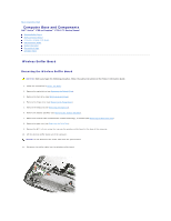
Back to Contents Page Computer Base and Components Dell™ Vostro™ 1700 and Inspiron™ 1720/1721 Service Manual Wireless Sniffer Board Audio Connector Board Consumer Infrared (CIR) Board USB Connector Board Modem Connector ExpressCard Cage Computer Base Wireless Sniffer Board Removing the Wireless - Dell Inspiron 1720 | Service Manual - Page 3
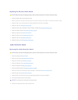
in the Product Information Guide. 1. Follow the instructions in Before You Begin. 2. Remove the optical drive (see Removing the Optical Drive). 3. Remove the hard drive (see Removing a Hard Drive). 4. Remove the hinge cover (see Removing the Hinge Cover). 5. Remove the keyboard (see Removing the - Dell Inspiron 1720 | Service Manual - Page 4
in the Product Information Guide. 1. Follow the instructions in Before You Begin. 2. Remove the optical drive (see Removing the Optical Drive). 3. Remove the hard drive (see Removing a Hard Drive). 4. Remove the hinge cover (see Removing the Hinge Cover). 5. Remove the keyboard (see Removing the - Dell Inspiron 1720 | Service Manual - Page 5
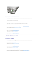
Replace the hard drive (see Replacing a Hard Drive). 10. Replace the optical drive (see Replacing the Optical Drive). USB Connector Board Removing the USB Connector Board CAUTION: Before you begin the following procedure, follow the safety instructions in the Product Information Guide. 1. Follow the - Dell Inspiron 1720 | Service Manual - Page 6
the Bluetooth Card). 8. Remove the palm rest (see Removing the Palm Rest). NOTICE: Do not disconnect the CIR cable from the system board. 9. Disconnect the USB cable from the USB connector board. 10. Remove the two M2.5 x 5-mm screws that secure the USB connnector board to the base of the computer - Dell Inspiron 1720 | Service Manual - Page 7
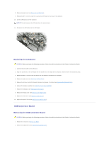
Product Information Guide. 1. Follow the instructions in Before You Begin. 2. Remove the modem (see Removing the Modem). 3. Remove the system board (see Removing the System Board Assembly). 4. Remove the M2.5 x 5-mm screw that secures the modem connector to the base of the computer. NOTICE: Before - Dell Inspiron 1720 | Service Manual - Page 8
assembly (see Replacing the Display Assembly). 6. Replace the keyboard (see Replacing the Keyboard). 7. Replace the hinge cover (see Replacing the Hinge Cover). 8. Replace the hard drive (see Replacing a Hard Drive). 9. Replace the optical drive (see Replacing the Optical Drive). Computer Base - Dell Inspiron 1720 | Service Manual - Page 9
in the Product Information Guide. 1. Follow the instructions in Before You Begin. 2. Remove the system board (see Removing the System Board Assembly). NOTE: When removing the system board to replace the computer base, it is not necessary to remove the processor, memory, or Mini-Card. 3. Remove - Dell Inspiron 1720 | Service Manual - Page 10
card reader (see Removing a Memory Card or Blank). NOTICE: To help prevent damage to the system board, you must remove the battery from the battery bay before you service the computer. NOTE: To avoid damage to the computer, use only the battery designed for this particular Dell computer. Do not use - Dell Inspiron 1720 | Service Manual - Page 11
7. Slide the battery release latches until they click into place. 8. Slide the battery out of the battery bay. 1 battery 2 battery release latch (2) 9. Turn the computer top-side up, open the display, and press the power button to ground the system board. Back to Contents Page - Dell Inspiron 1720 | Service Manual - Page 12
the BIOS Dell™ Vostro™ 1700 and Inspiron™ 1720/1721 Service Manual Flashing the BIOS From a CD Flashing the BIOS From the Hard Drive If a BIOS-update program CD is provided with a new system board, flash the BIOS from the CD. If you do not have a BIOS-update program CD, flash the BIOS from the hard - Dell Inspiron 1720 | Service Manual - Page 13
9. Double-click the file icon on the desktop and follow the instructions on the screen. Back to Contents Page - Dell Inspiron 1720 | Service Manual - Page 14
Inspiron™ 1720/1721 Service Manual Removing the Bluetooth Card Replacing the Bluetooth Card CAUTION: Before you begin any of the procedures in this section, follow the safety instructions in the Product Information Guide. If you ordered a card with Bluetooth wireless technology with your computer - Dell Inspiron 1720 | Service Manual - Page 15
and Inspiron™ 1720/1721 Service Manual Memory Card Blanks Removing a Memory Card or Blank Installing a Memory Card The memory card reader provides a fast and convenient way to view and share digital photos, music, and videos stored on a memory card. NOTE: A memory card is not a bootable device. The - Dell Inspiron 1720 | Service Manual - Page 16
The computer recognizes the memory card and automatically loads the appropriate device driver. If the configuration program tells you to load the manufacturer's drivers, use the media that came with the memory card, if applicable. Back to Contents Page - Dell Inspiron 1720 | Service Manual - Page 17
Coin-Cell Battery Dell™ Vostro™ 1700 and Inspiron™ 1720/1721 Service Manual Removing the Coin-Cell Battery Replacing the Coin-Cell Battery Removing the Coin-Cell Battery CAUTION: Before you begin any of the procedures in this section, follow the safety instructions in the Product Information Guide - Dell Inspiron 1720 | Service Manual - Page 18
in this section, follow the safety instructions in the Product Information Guide. 1. Follow the procedures in Before You Begin. 2. Connect the coin-cell battery cable to the system board. 3. Slide the coin-cell battery into the mylar sleeve. 4. Replace the memory module cover and tighten the captive - Dell Inspiron 1720 | Service Manual - Page 19
Page Processor Module Dell™ Vostro™ 1700 and Inspiron™ 1720/1721 Service Manual Removing the Processor Module Replacing the Processor Module Removing the Processor Module CAUTION: Before you begin the following procedure, follow the safety instructions in the Product Information Guide. 1. Follow the - Dell Inspiron 1720 | Service Manual - Page 20
module to the system board. 3. Replace the Bluetooth Card). 6. Replace the display assembly (see Replacing the Display Assembly). 7. Replace the keyboard (see Replacing the Keyboard). 8. Replace the hinge cover (see Replacing the Hinge Cover). 9. Replace the hard drive (see Replacing a Hard Drive - Dell Inspiron 1720 | Service Manual - Page 21
- Dell Inspiron 1720 | Service Manual - Page 22
and Inspiron™ 1720/1721 Service Manual Removing the Processor Thermal-Cooling Assembly Replacing the Processor Thermal-Cooling Assembly Removing the Processor Thermal-Cooling Assembly CAUTION: Before you begin the following procedure, follow the safety instructions in the Product Information Guide - Dell Inspiron 1720 | Service Manual - Page 23
(see Replacing the Display Assembly). 6. Replace the keyboard (see Replacing the Keyboard). 7. Replace the hinge cover (see Replacing the Hinge Cover). 8. Replace the hard drive (see Replacing a Hard Drive). 9. Replace the optical drive (see Replacing the Optical Drive). Back to Contents Page - Dell Inspiron 1720 | Service Manual - Page 24
Page Display Dell™ Vostro™ 1700 and Inspiron™ 1720/1721 Service Manual Display Assembly Display Bezel Display Panel Display Latch Camera and Microphone Assembly Display Assembly Removing the Display Assembly CAUTION: Before you begin the following procedure, follow the safety instructions in the - Dell Inspiron 1720 | Service Manual - Page 25
display cable to the display cable connector on the system board. 7. Replace and tighten the captive grounding screw. 8. Replace the keyboard (see Replacing the Keyboard). 9. Replace the hinge cover (see Replacing the Hinge Cover). 10. Replace the two M2.5 x 8-mm screws on the back of the computer. - Dell Inspiron 1720 | Service Manual - Page 26
begin the following procedure, follow the safety instructions in the Product Information Guide. 1. Follow the instructions in Before You Begin. 2. Remove the hinge cover (see Removing the Hinge Cover). 3. Remove the keyboard (see Removing the Keyboard). 4. Remove the display assembly (see Removing - Dell Inspiron 1720 | Service Manual - Page 27
begin the following procedure, follow the safety instructions in the Product Information Guide. 1. Follow the instructions in Before You Begin. 2. Remove the hinge cover (see Removing the Hinge Cover). 3. Remove the keyboard (see Replacing the Keyboard). 4. Remove the display assembly (see Removing - Dell Inspiron 1720 | Service Manual - Page 28
(see Replacing the Keyboard). 12. Replace the hinge cover (see Replacing the Hinge Cover). Display Latch Removing the Display Latch CAUTION: Before you begin the following procedure, follow the safety instructions in the Product Information Guide. 1. Follow the instructions in Before You Begin - Dell Inspiron 1720 | Service Manual - Page 29
cover (see Removing the Hinge Cover). 3. Remove the keyboard (see Removing the Keyboard). 4. Remove the display assembly (see Removing the Display display latch to the right and lift each side to detach it from the guide slot on the display cover. 9. Using your fingers, gently separate the display - Dell Inspiron 1720 | Service Manual - Page 30
begin the following procedure, follow the safety instructions in the Product Information Guide. 1. Follow the instructions in Before You Begin. 2. Remove the hinge cover (see Removing the Hinge Cover). 3. Remove the keyboard (see Removing the Keyboard). 4. Remove the display assembly (see Removing - Dell Inspiron 1720 | Service Manual - Page 31
the following procedure, follow the safety instructions in the Product Information Guide. 1. Follow the instructions in Before You Begin. 2. Align assembly (see Replacing the Display Assembly). 7. Replace the keyboard (see Replacing the Keyboard). 8. Replace the hinge cover (see Replacing the Hinge - Dell Inspiron 1720 | Service Manual - Page 32
Back to Contents Page Fan Dell™ Vostro™ 1700 and Inspiron™ 1720/1721 Service Manual Removing the Fan Replacing the Fan Removing the Fan CAUTION: Before you begin the following procedure, follow the safety instructions in the Product Information Guide. 1. Follow the instructions in Before You Begin. - Dell Inspiron 1720 | Service Manual - Page 33
safety instructions in the Product Information Guide. 1. Align the screw holes on the fan with the holes on the base of the computer. 2. In sequential order, replace the four M2.5 x 5-mm screws to secure the fan to the base of the computer. 3. Connect the fan connector to the system board connector - Dell Inspiron 1720 | Service Manual - Page 34
Inspiron™ 1720/1721 Service Manual Removing the FCM Replacing the FCM The Flash Cache Module (FCM) is an internal flash drive that helps improve the performance of your computer. If you ordered an FCM with your computer, the card is already installed. NOTE: The FCM is not supported on the Inspiron - Dell Inspiron 1720 | Service Manual - Page 35
in the Product Information Guide. 1. Follow the instructions in Before You Begin. 2. Remove the optical drive (see Removing the Optical Drive). 3. Remove the hard drive (see Removing a Hard Drive). 4. Remove the hinge cover (see Removing the Hinge Cover). 5. Remove the keyboard (see Removing the - Dell Inspiron 1720 | Service Manual - Page 36
(see Replacing the Display Assembly). 6. Replace the keyboard (see Replacing the Keyboard). 7. Replace the hinge cover (see Replacing the Hinge Cover). 8. Replace the hard drive (see Replacing a Hard Drive). 9. Replace the optical drive (see Replacing the Optical Drive). Back to Contents Page - Dell Inspiron 1720 | Service Manual - Page 37
and Inspiron™ 1720/1721 Service Manual Removing a Hard Drive Replacing a Hard Drive Depending on the configuration you ordered, your computer may have two hard drives, a primary hard drive and an optional secondary hard drive. NOTE: Dell does not guarantee compatibility or provide support for hard - Dell Inspiron 1720 | Service Manual - Page 38
the hard drive. 6. Replace the hard drive cover, and then tighten the screws. 7. Install the operating system for your computer, as needed (see "Restoring Your Operating System" in your Owner's Manual). 8. Install the drivers and utilities for your computer, as needed (see "Reinstalling Drivers and - Dell Inspiron 1720 | Service Manual - Page 39
Page Hinge Cover Dell™ Vostro™ 1700 and Inspiron™ 1720/1721 Service Manual Removing the Hinge Cover Replacing the Hinge Cover Removing the Hinge Cover CAUTION: Before you begin any of the procedures in this section, follow the safety instructions in the Product Information Guide. NOTICE: The hinge - Dell Inspiron 1720 | Service Manual - Page 40
Inspiron™ 1720/1721 Service Manual Removing the Keyboard Replacing the Keyboard For more information about the keyboard, see "Using the Keyboard and Touchpad" in your Owner's Manual. Removing the Keyboard CAUTION: Before you begin any of the procedures in this section, follow the safety instructions - Dell Inspiron 1720 | Service Manual - Page 41
1 tabs (6) 3 notch on keyboard 5 palm rest 2 keyboard connector 4 tab on palm rest 5. Replace the four M2 x 3-mm screws at the top of the keyboard. 6. Replace the hinge cover (see Replacing the Hinge Cover). Back to Contents Page - Dell Inspiron 1720 | Service Manual - Page 42
Latch Assembly Dell™ Vostro™ 1700 and Inspiron™ 1720/1721 Service Manual Removing the Battery Latch Assembly Replacing the Battery Latch Assembly Removing the Battery Latch Assembly CAUTION: Before you begin the following procedure, follow the safety instructions in the Product Information Guide - Dell Inspiron 1720 | Service Manual - Page 43
Back to Contents Page - Dell Inspiron 1720 | Service Manual - Page 44
to Contents Page Memory Dell™ Vostro™ 1700 and Inspiron™ 1720/1721 Service Manual Removing a Memory Module Replacing a Memory Module Your computer has two user-accessible SODIMM sockets, one accessed from beneath the keyboard (DIMM A), and the other accessed from the bottom of the computer (DIMM - Dell Inspiron 1720 | Service Manual - Page 45
of the procedures in this section, follow the safety instructions in the Product Information Guide. DIMM A Memory Module The DIMM A memory module is located under the keyboard. 1. Follow the procedures in Before You Begin. 2. Align the notch in the memory module edge connector with the tab in the - Dell Inspiron 1720 | Service Manual - Page 46
on the computer. As the computer boots, it detects the additional memory and automatically updates the system configuration information. To confirm the amount of memory installed in the computer, click Start ® Help and Support® Dell System Information. DIMM B Memory Module The DIMM B memory module - Dell Inspiron 1720 | Service Manual - Page 47
outlet. 8. Turn on the computer. As the computer boots, it detects the additional memory and automatically updates the system configuration information. To confirm the amount of memory installed in the computer, click Start ® Help and Support® Dell System Information. Back to Contents Page - Dell Inspiron 1720 | Service Manual - Page 48
Cards Dell™ Vostro™ 1700 and Inspiron™ 1720/1721 Service Manual Removing a Mini Card Replacing a Mini Card CAUTION: Before you begin any of the procedures in this section, follow the safety instructions in the Product Information Guide. If you ordered a wireless Mini Card with your computer, the - Dell Inspiron 1720 | Service Manual - Page 49
2 WLAN card 5. Release the WLAN card by pushing the metal securing tabs toward the back of the computer until the card pops up slightly. 6. Lift the WLAN card out of its system board connector. 1 metal securing tabs (2) 2 WLAN card Mobile Broadband or WWAN Card NOTE: WWAN is also available on - Dell Inspiron 1720 | Service Manual - Page 50
cables from the WWAN card. 1 antenna cable connectors (2) 2 WWAN card 5. Release the WWAN card by pushing the metal securing tabs toward the back of the computer until the card pops up slightly. 6. Lift the WWAN card out of its system board connector. - Dell Inspiron 1720 | Service Manual - Page 51
WWAN card WPAN Card 1. Follow the procedures in Before You Begin. 2. Turn the computer over. 3. Loosen the two captive screws on the Mini Card compartment cover, then tabs toward the back of the computer until the card pops up slightly. 6. Lift the WPAN card out of its system board connector. - Dell Inspiron 1720 | Service Manual - Page 52
the cover and tighten the captive screws. Mobile Broadband or WWAN Card NOTICE: The connectors are keyed to ensure correct insertion. If you feel resistance, check the connectors on the card and on the system board, and realign the card. NOTICE: To avoid damage to the WWAN card, never place cables - Dell Inspiron 1720 | Service Manual - Page 53
WPAN Card NOTICE: The connectors are keyed to ensure correct insertion. If you feel resistance, check the connectors on the card and on the system board, and realign the card. NOTICE: To avoid damage to the WPAN card, never place cables under the card. 1. Insert the WPAN card connector at a 45- - Dell Inspiron 1720 | Service Manual - Page 54
™ 1700 and Inspiron™ 1720/1721 Service Manual Removing the Modem Replacing the Modem Removing the Modem CAUTION: Before you begin the following procedure, follow the safety instructions in the Product Information Guide. 1. Follow the instructions in Before You Begin. 2. Remove the optical drive (see - Dell Inspiron 1720 | Service Manual - Page 55
3-mm screws and secure the modem to the system board and the base of the computer. 5. Replace the palm rest (see Replacing the Palm Rest). 6. Replace the internal card with Bluetooth wireless technology, if installed (see Replacing the Bluetooth Card). 7. Replace the display assembly (see Replacing - Dell Inspiron 1720 | Service Manual - Page 56
Page Optical Drive Dell™ Vostro™ 1700 and Inspiron™ 1720/1721 Service Manual Removing the Optical Drive Replacing the Optical Drive Removing the Optical Drive CAUTION: Before you begin any of the procedures in this section, follow the safety instructions in the Product Information Guide. 1. Follow - Dell Inspiron 1720 | Service Manual - Page 57
Page Palm Rest Dell™ Vostro™ 1700 and Inspiron™ 1720/1721 Service Manual Removing the Palm Rest Replacing the Palm Rest Removing the Palm Rest CAUTION: Before you begin the following procedure, follow the safety instructions in the Product Information Guide. 1. Follow the instructions in Before You - Dell Inspiron 1720 | Service Manual - Page 58
cable and the cable for the Bluetooth card with wireless technology are properly routed before snapping the palm rest into place. 1. Align the palm rest with the base of the computer and gently snap it into place. 2. Connect the touch pad connector to the system board. 3. Replace the six M2.0 x 3-mm - Dell Inspiron 1720 | Service Manual - Page 59
to Contents Page ExpressCards Dell™ Vostro™ 1700 and Inspiron™ 1720/1721 Service Manual ExpressCard Blanks Removing an Owner's Manual for information on supported ExpressCards. NOTE: An ExpressCard is not a bootable device. 1 ExpressCard/34 2 ExpressCard/54 ExpressCard Blanks Your computer shipped - Dell Inspiron 1720 | Service Manual - Page 60
. Check the card orientation and try again. 1 slot 2 ExpressCard The computer recognizes the ExpressCard and automatically loads the appropriate device driver. If the configuration program tells you to load the manufacturer's drivers, use the media that came with the ExpressCard. Back to Contents - Dell Inspiron 1720 | Service Manual - Page 61
Back to Contents Page Pin Assignments for I/O Connectors Dell™ Vostro™ 1700 and Inspiron™ 1720/1721 Service Manual USB Connector Video Connector S-Video TV-Out Connector 1394 Connector USB Connector Pin Signal 1 USB5V+ 2 USBP- 3 USBP+ 4 GND Video Connector Pin Signal Pin Signal 1 CRT_R 9 - Dell Inspiron 1720 | Service Manual - Page 62
S-Video Pin Signal 1 GND 2 GND 3 DLUMA-L 4 DCRMA-L 1394 Connector Pin Signal 1 TPB2 TPB+ 3 TPA4 TPA+ Back to Contents Page - Dell Inspiron 1720 | Service Manual - Page 63
Page Speaker Assembly Dell™ Vostro™ 1700 and Inspiron™ 1720/1721 Service Manual Removing the Speaker Assembly Replacing the Speaker Assembly Removing the Speaker Assembly CAUTION: Before you begin the following procedure, follow the safety instructions in the Product Information Guide. 1. Follow the - Dell Inspiron 1720 | Service Manual - Page 64
(see Replacing the Bluetooth Card). 6. Replace the display assembly (see Replacing the Display Assembly). 7. Replace the keyboard (see Replacing the Keyboard). 8. Replace the hinge cover (see Replacing the Hinge Cover). 9. Replace the hard drive (see Replacing a Hard Drive). 10. Replace the - Dell Inspiron 1720 | Service Manual - Page 65
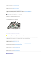
to Contents Page System Board Assembly Dell™ Vostro™ 1700 and Inspiron™ 1720/1721 Service Manual Removing the System Board Assembly Replacing the System Board Assembly The system board's BIOS chip contains the Service Tag, which is also visible on a barcode label on the bottom of the computer. The - Dell Inspiron 1720 | Service Manual - Page 66
computer. 1 speaker cable connector 2 sniffer/audio cable connector 3 CIR cable connector 4 Bluetooth cable connector 5 USB I/O cable connector Replacing the System Board Assembly CAUTION: Before you begin the following procedure, follow the safety instructions in the Product Information Guide - Dell Inspiron 1720 | Service Manual - Page 67
time only. Otherwise, you must enter the system setup program to change the default boot order. 24. Flash update the BIOS (see Flashing the BIOS for more information). 25. Enter the system setup program to update the BIOS on the new system board with the computer Service Tag. Back to Contents Page - Dell Inspiron 1720 | Service Manual - Page 68
Back to Contents Page Dell™ Vostro™ 1700 and Inspiron™ 1720/1721 Service Manual NOTE: A NOTE indicates important information that helps you make better use of your computer. NOTICE: A NOTICE indicates either potential damage to hardware or loss of data and tells you how to avoid the problem. CAUTION
-
 1
1 -
 2
2 -
 3
3 -
 4
4 -
 5
5 -
 6
6 -
 7
7 -
8
-
9
-
10
-
11
-
12
-
13
-
14
-
15
-
16
-
17
-
18
-
19
-
20
-
21
-
22
-
23
-
24
-
25
-
26
-
27
-
28
-
29
-
30
-
31
-
32
-
33
-
34
-
35
-
36
-
37
-
38
-
39
-
40
-
41
-
42
-
43
-
44
-
45
-
46
-
47
-
48
-
49
-
50
-
51
-
52
-
53
-
54
-
55
-
56
-
57
-
58
-
59
-
60
-
61
-
62
-
63
-
64
-
65
-
66
-
67
-
68
 |
 |

Dell™ Vostro™ 1700 and Inspiron™ 1720/1721 Service Manual
Notes, Notices, and Cautions
Information in this document is subject to change without notice.
© 2007 Dell Inc. All rights reserved.
Reproduction in any manner whatsoever without the written permission of Dell Inc. is strictly forbidden.
Trademarks used in this text:
Dell
, the
DELL
logo,
Inspiron
, and
Vostro
are trademarks of Dell Inc.;
Microsoft
,
Windows, and Windows Vista
are either trademarks or registered
trademarks of Microsoft Corporation in the United States and/or other countries.
Other trademarks and trade names may be used in this document to refer to either the entities claiming the marks and names or their products. Dell Inc. disclaims any
proprietary interest in trademarks and trade names other than its own.
Model PP22X
June 2007
Rev. A00
Before You Begin
ExpressCards
Using the Memory Card Reader
Optical Drive
Hard Drive
Hinge Cover
Internal Card With Bluetooth
®
Wireless Technology
Keyboard
Memory
Display
Palm Rest
Wireless Mini Cards
Flash Cache Module (FCM)
Modem
Coin
-
Cell Battery
Graphics Card Assembly
Processor Thermal
-
Cooling Assembly
Processor Module
Fan
Speaker Assembly
System Board Assembly
Computer Base and Components
Battery Latch Assembly
Flashing the BIOS
Pin Assignments for I/O Connectors
NOTE:
A NOTE indicates important information that helps you make better use of your computer.
NOTICE:
A NOTICE indicates either potential damage to hardware or loss of data and tells you how to avoid the problem.
CAUTION:
A CAUTION indicates potential for property damage, personal injury, or death.